check engine YAMAHA TDM 850 2000 Owners Manual
[x] Cancel search | Manufacturer: YAMAHA, Model Year: 2000, Model line: TDM 850, Model: YAMAHA TDM 850 2000Pages: 99, PDF Size: 10.69 MB
Page 12 of 99
DESCRIPTION
2-2
2
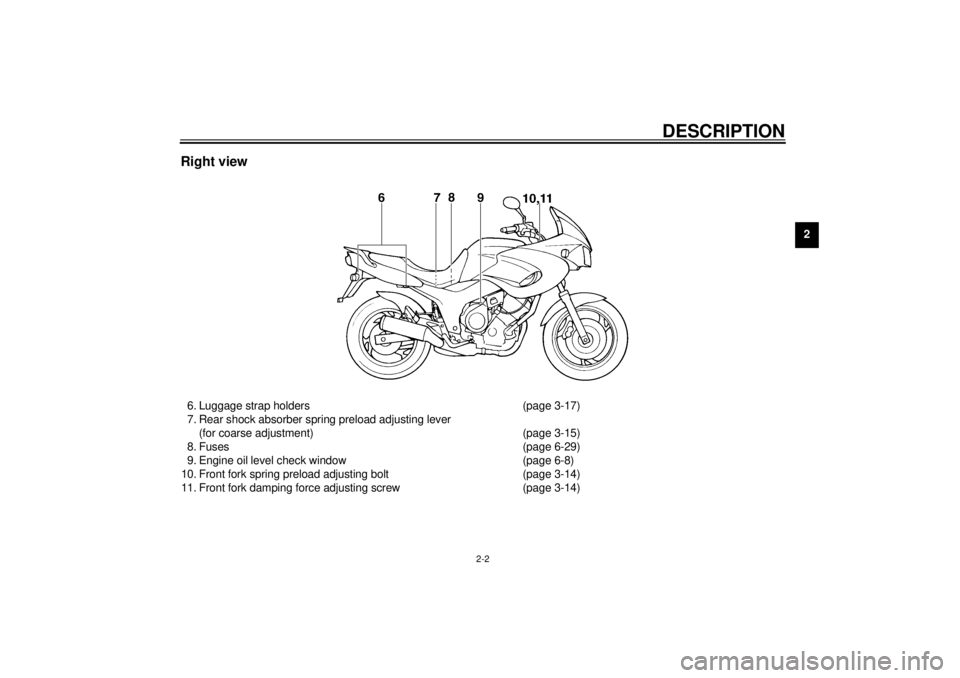
Right view6. Luggage strap holders (page 3-17)
7. Rear shock absorber spring preload adjusting lever
(for coarse adjustment) (page 3-15)
8. Fuses (page 6-29)
9. Engine oil level check window (page 6-8)
10. Front fork spring preload adjusting bolt (page 3-14)
11. Front fork damping force adjusting screw (page 3-14)
E_4tx_Description.fm Page 2 Saturday, October 16, 1999 9:36 AM
Page 16 of 99
INSTRUMENT AND CONTROL FUNCTIONS
3-2
3
EAU00048
(Parking)
The steering is locked in this position,
and the taillight and auxiliary light come
on but all other circuits are off. The key
can be removed in this position.
To use the parking position, first lock
the steering, then turn the key to “ ”.
Do not use this position for an extend-
ed length of time as the battery may
discharge.
EAU00056
Indicator lights
EAU00058
Turn indicator lights “ ” / “ ”
The corresponding indicator flashes
when the turn switch is moved to the
left or right.
EAU00061
Neutral indicator light “ ”
This indicator comes on when the
transmission is in neutral.
EAU00063
High beam indicator light “ ”
This indicator comes on when the
headlight high beam is used.
EAU01707
Coolant temperature indicator light
“”
This indicator light comes on when the
engine overheats. If the light comes on,
stop the engine immediately and allow
the engine to cool. To check that the in-
dicator light is working properly:l
Turn the engine stop switch to
“ ” and the main switch to “ON”.
l
Put the transmission in neutral or
apply the clutch lever.
l
Push the start switch.
If the indicator light does not come on
while pushing the start switch, have a
Yamaha dealer inspect the electrical
circuit.
EC000002
CAUTION:@ When the engine is overheated, do
not continue riding. @
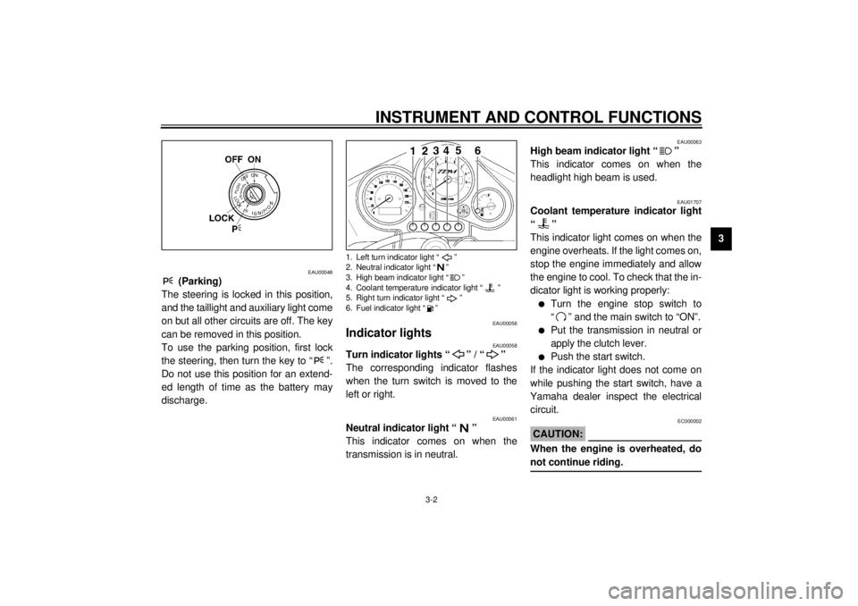
1. Left turn indicator light “ ”
2. Neutral indicator light “ ”
3. High beam indicator light “ ”
4. Coolant temperature indicator light “ ”
5. Right turn indicator light “ ”
6. Fuel indicator light “ ”
E_4tx_Functions.fm Page 2 Saturday, October 16, 1999 9:36 AM
Page 17 of 99
INSTRUMENT AND CONTROL FUNCTIONS
3-3
3
EAU01666
Fuel indicator light “ ”
When the fuel level drops below ap-
proximately 3,1 L, this light will come
on. When this light comes on, fill the
tank at the first opportunity.
To check that the indicator light is work-
ing properly:l
Turn the engine stop switch to
“ ” and the main switch to “ON”.
l
Put the transmission in neutral or
apply the clutch lever.
l
Push the start switch.
If the indicator light does not come on
while pushing the start switch, have a
Yamaha dealer inspect the electrical
circuit.
EAU01667*
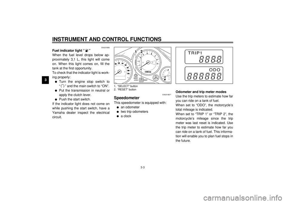
SpeedometerThis speedometer is equipped with:l
an odometer
l
two trip odometers
l
a clockOdometer and trip meter modes
Use the trip meters to estimate how far
you can ride on a tank of fuel.
When set to “ODO”, the motorcycle’s
total mileage is indicated.
When set to “TRIP 1” or “TRIP 2”, the
motorcycle’s mileage since the trip
meter was last reset is indicated. Use
the trip meter to estimate how far you
can ride on a tank of fuel. This informa-
tion will enable you to plan fuel stops in
the future.
1. “SELECT” button
2. “RESET” button
E_4tx_Functions.fm Page 3 Saturday, October 16, 1999 9:36 AM
Page 31 of 99

INSTRUMENT AND CONTROL FUNCTIONS
3-17
3
EAU00324
Luggage strap holdersThere are four luggage strap holders
below the passenger seat, two of which
can be turned outward for easier ac-
cess.
EAU00330
SidestandThis model is equipped with an ignition
circuit cut-off system. The motorcycle
must not be ridden when the sidestand
is down. The sidestand is located on
the left side of the frame. (Refer to
page 5-1 for an explanation of this sys-
tem.)
EW000044
WARNING
@ This motorcycle must not be operat-
ed with the sidestand in the down
position. If the stand is not properly
retracted, it could contact the
ground and distract the operator, re-
sulting in a possible loss of control.
Yamaha has designed into this
motorcycle a lockout system to as-
sist the operator in fulfilling the re-
sponsibility of retracting the
sidestand. Please check carefully
the operating instructions listed be-
low and if there is any indication of a
malfunction, return the motorcycle
to a Yamaha dealer immediately for
repair. @
EAU00331
Sidestand/clutch switch
operation checkCheck the operation of the sidestand
switch and clutch switch against the in-
formation below.CD-11E
1. Luggage strap holder (´ 4)
TURN THE MAIN SWITCH TO “ON”
AND THE ENGINE STOP SWITCH TO
“”.TRANSMISSION IS IN GEAR AND
SIDESTAND IS UP.PULL IN CLUTCH LEVER AND
PUSH THE START SWITCH.ENGINE WILL START.CLUTCH SWITCH IS OK.
E_4tx_Functions.fm Page 17 Saturday, October 16, 1999 9:36 AM
Page 35 of 99

4-1
4
EAU01114
4-PRE-OPERATION CHECKSOwners are personally responsible for their vehicle’s condition. Your motorcycle’s vital functions can start to deteriorate
quickly and unexpectedly, even if it remains unused (for instance, if it is exposed to the elements). Any damage, fluid leak or
loss of tire pressure could have serious consequences. Therefore, it is very important that, in addition to a thorough visual in-
spection, you check the following points before each ride.
EAU00340
PRE-OPERATION CHECK LIST
ITEM CHECKS PAGE
Front brake• Check operation, fluid level and brake fluid leakage.
• Fill with DOT 4 brake fluid if necessary.
3-9, 6-20 ~ 6-23
Rear brake• Check operation, fluid level and brake fluid leakage.
• Fill with DOT 4 brake fluid if necessary.
Clutch• Check operation, condition and free play.
• Adjust if necessary.3-8, 6-19 ~ 6-20
Throttle grip and housing• Check for smooth operation.
• Lubricate if necessary.6-16, 6-25
Engine oil• Check oil level.
• Fill with oil if necessary.6-8 ~ 6-10
Coolant reservoir tank• Check coolant level.
• Fill with coolant if necessary.6-10
Drive chain• Check chain slack and condition.
• Adjust if necessary.6-23 ~ 6-24
Wheels and tires• Check tire pressure, wear and damage. 6-17 ~ 6-19, 6-28
Control and meter cables• Check for smooth operation.
• Lubricate if necessary.6-24 ~ 6-25
Brake and shift pedal
shafts• Check for smooth operation.
• Lubricate if necessary.6-25
E_4tx_Preop.fm Page 1 Saturday, October 16, 1999 9:36 AM
Page 39 of 99

5-1
5
EAU00372
5-OPERATION AND IMPORTANT RIDING POINTS
EAU00373
WARNING
@ l
Before riding this motorcycle,
become thoroughly familiar
with all operating controls and
their functions. Consult a
Yamaha dealer regarding any
control or function that you do
not thoroughly understand.
l
Never start your engine or let it
run for any length of time in a
closed area. The exhaust fumes
are poisonous and can cause
loss of consciousness and
death within a short time. Al-
ways operate your motorcycle
in an area with adequate ventila-
tion.
l
Before starting out, always be
sure the sidestand is up. Failure
to retract the sidestand com-
pletely can result in a serious
accident when you try to turn a
corner.
@
EAU01665*
Starting the engineNOTE:@ This motorcycle is equipped with an ig-
nition circuit cut-off system. The engine
can be started only under one of the
following conditions:l
The transmission is in neutral.
l
The sidestand is up, the transmis-
sion is in gear and the clutch is dis-
engaged.
The motorcycle must not be ridden
when the sidestand is down.
@
EW000054
WARNING
@ Before going through the following
steps, check the function of the
sidestand switch and clutch switch.
(Refer to page 3-17.) @
E_4tx_Operation.fm Page 1 Saturday, October 16, 1999 9:37 AM
Page 41 of 99
OPERATION AND IMPORTANT RIDING POINTS
5-3
51. Turn the main switch to “ON” and
the engine stop switch to “ ”.
EC000035
CAUTION:@ If the fuel indicator light comes on,
check the fuel level. If necessary, fill
the tank with fuel. @2. Shift the transmission into neutral.NOTE:@ When the transmission is in neutral, the
neutral indicator light should be on. If
the light does not come on, ask a
Yamaha dealer to inspect it. @3. Turn on the starter (choke) and
completely close the throttle grip.
4. Start the engine by pushing the
start switch.
NOTE:@ If the engine fails to start, release the
start switch, wait a few seconds, then
try again. Each attempt should be as
short as possible to preserve the bat-
tery. Do not crank the engine more
than 10 seconds on any one attempt. @
ECA00022
CAUTION:@ The coolant temperature indicator
light and the fuel indicator light
should come on when the start
switch is pushed and should go off
when the start switch is released. If
the coolant temperature indicator
light remains on, immediately stop
the engine and have a Yamaha deal-
er check the monitoring circuits. If
the fuel indicator light remains on,
add sufficient fuel. @
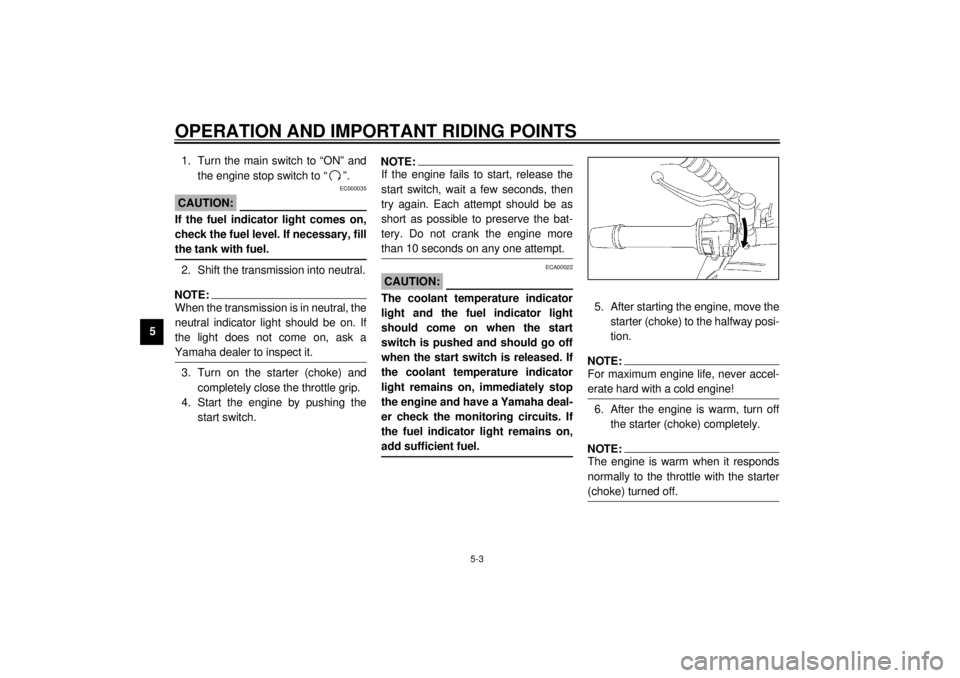
5. After starting the engine, move the
starter (choke) to the halfway posi-
tion.NOTE:@ For maximum engine life, never accel-
erate hard with a cold engine! @6. After the engine is warm, turn off
the starter (choke) completely.NOTE:@ The engine is warm when it responds
normally to the throttle with the starter
(choke) turned off. @
E_4tx_Operation.fm Page 3 Saturday, October 16, 1999 9:37 AM
Page 46 of 99
6
PERIODIC MAINTENANCE AND MINOR REPAIR
Tool kit................................................................... 6-1
Periodic maintenance and lubrication ................... 6-2
Cowling and panel removal and installation.......... 6-5
Cowlings A and B ................................................. 6-5
Panels A and B ..................................................... 6-6
Spark plugs........................................................... 6-6
Engine oil .............................................................. 6-8
Cooling system ................................................... 6-10
Changing the coolant .......................................... 6-11
Air filter ............................................................... 6-13
Carburetor adjustment ........................................ 6-15
Idle speed adjustment ........................................ 6-15
Throttle cable free play inspection ...................... 6-16
Valve clearance adjustment ................................ 6-16
Tires .................................................................... 6-17
Clutch lever free play adjustment........................ 6-19
Rear brake pedal height adjustment ................... 6-20
Brake light switch adjustment ............................. 6-21
Checking the front and rear brake pads.............. 6-21
Inspecting the brake fluid level............................ 6-22
Brake fluid replacement ...................................... 6-23Drive chain slack check ...................................... 6-23
Drive chain slack adjustment ............................. 6-23
Drive chain lubrication........................................ 6-24
Cable inspection and lubrication ........................ 6-24
Throttle cable and grip lubrication ...................... 6-25
Brake and shift pedal lubrication ........................ 6-25
Brake and clutch lever lubrication ...................... 6-25
Sidestand lubrication.......................................... 6-26
Rear suspension lubrication............................... 6-26
Front fork inspection ........................................... 6-27
Steering inspection ............................................ 6-27
Wheel bearings .................................................. 6-28
Battery................................................................ 6-28
Fuse replacement .............................................. 6-29
Headlight bulb replacement ............................... 6-30
Tail/brake light bulb replacement ........................ 6-31
Turn signal light bulb replacement...................... 6-32
Troubleshooting .................................................. 6-32
Troubleshooting chart ......................................... 6-33
Engine overheating ............................................ 6-34
E_4tx_PeriodicTOC.fm Page 1 Saturday, October 16, 1999 9:37 AM
Page 49 of 99

PERIODIC MAINTENANCE AND MINOR REPAIR
6-3
6
12
*Swingarm• Check swingarm pivoting point for play.
• Correct if necessary.
• Lubricate with molybdenum disulfide grease every 24,000 km
or 24 months (whichever comes first).ÖÖ
13 Drive chain• Check chain slack.
• Adjust if necessary. Make sure that the rear wheel is properly aligned.
• Clean and lubricate. Every 500 km and after washing the
motorcycle or riding in the rain
14*Steering bearings• Check bearing play and steering for roughness.
• Correct accordingly.
• Lubricate with lithium soap base grease every 24,000 km
or 24 months (whichever comes first).ÖÖ
15*Chassis fasteners• Make sure that all nuts, bolts and screws are properly tightened.
• Tighten if necessary.ÖÖ
16 Sidestand• Check operation.
• Lubricate and repair if necessary.ÖÖ
17*Sidestand switch• Check operation.
• Replace if necessary.ÖÖÖ
18*Front fork• Check operation and for oil leakage.
• Correct accordingly.ÖÖ
19*Rear shock absorber
assembly• Check operation and shock absorber for oil leakage.
• Replace shock absorber assembly if necessary. ÖÖ
20*Rear shock absorber
assembly pivoting points• Check operation.
• Lubricate with molybdenum disulfide grease every 24,000 km
or 24 months (whichever comes first).ÖÖ
21*Carburetors• Check engine idling speed, synchronization and starter operation.
• Adjust if necessary.ÖÖÖ
22 Engine oil• Check oil level and vehicle for oil leakage.
• Correct if necessary.
• Change. (Warm engine before draining.)ÖÖÖ
23 Engine oil filter element
• Replace.ÖÖ NO. ITEM CHECKS AND MAINTENANCE JOBSINITIAL
(1,000 km)EVERY
6,000 km
or
6 months
(whichever
comes first)12,000 km
or
12 months
(whichever
comes first)
E_4tx_Periodic.fm Page 3 Saturday, October 16, 1999 9:37 AM
Page 54 of 99

PERIODIC MAINTENANCE AND MINOR REPAIR
6-8
6
EAU01692
Engine oilOil level inspection
1. Place the motorcycle on a level
place. Warm up the engine at idle
for 15 minutes.NOTE:@ Be sure the motorcycle is positioned
straight up when checking the oil level.
A slight tilt toward the side can result in
false readings. @
2. The oil tank is located behind the
engine cylinders. With the engine
stopped, check the oil level
through the level window located
on the right side of the oil tank.
3. The oil level should be between
the maximum and minimum
marks. If the level is low, fill engine
with sufficient oil to raise it to the
specified level.Engine oil and oil filter element re-
placement
1. Warm up the engine for a few min-
utes.
2. Stop the engine. Place an oil pan
under the engine and remove the
oil filler cap.
3. Remove the drain bolts and drain
the oil.
4. Remove the oil filter cover bolts
and oil filter.
1. Oil level window
2. Minimum level mark
3. Maximum level mark
1. Engine oil filler cap
1. Engine oil drain bolt a
E_4tx_Periodic.fm Page 8 Saturday, October 16, 1999 9:37 AM