horn YAMAHA TDM 850 2001 Owners Manual
[x] Cancel search | Manufacturer: YAMAHA, Model Year: 2001, Model line: TDM 850, Model: YAMAHA TDM 850 2001Pages: 110, PDF Size: 12.15 MB
Page 20 of 110

INSTRUMENT AND CONTROL FUNCTIONS
3-5
3
EAU00109
Anti-theft alarm (optional) This motorcycle can be equipped with
an optional anti-theft alarm by a
Yamaha dealer. Contact a Yamaha
dealer for more information.
EAU00110
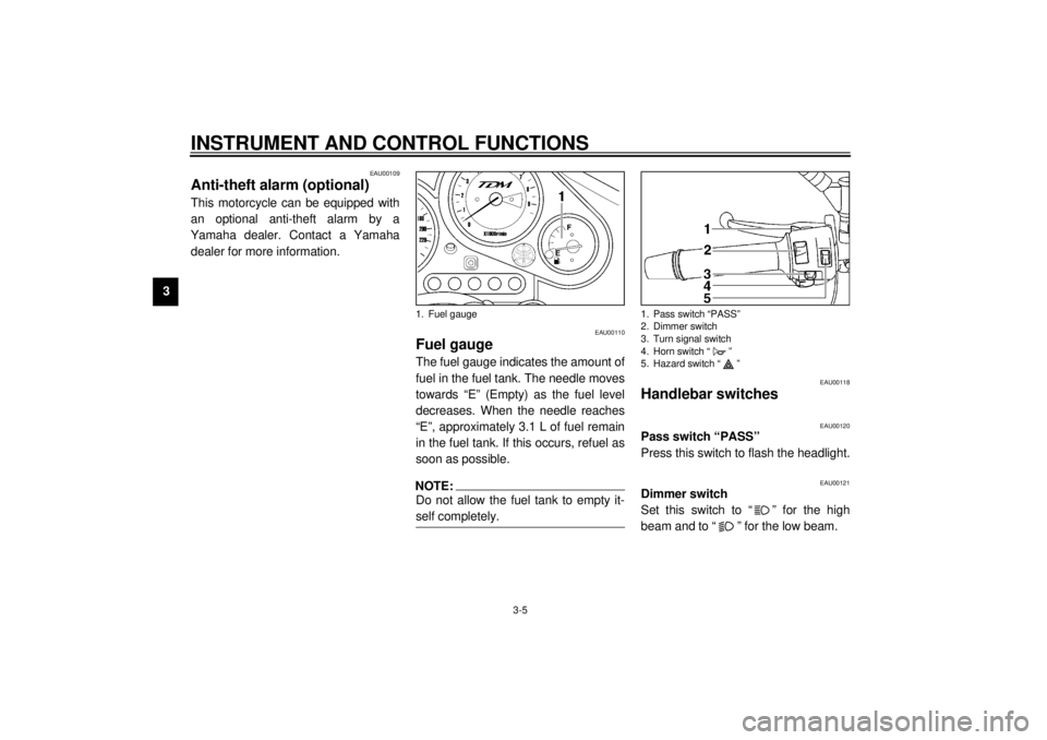
Fuel gauge The fuel gauge indicates the amount of
fuel in the fuel tank. The needle moves
towards “E” (Empty) as the fuel level
decreases. When the needle reaches
“E”, approximately 3.1 L of fuel remain
in the fuel tank. If this occurs, refuel as
soon as possible.NOTE:@ Do not allow the fuel tank to empty it-
self completely. @
EAU00118
Handlebar switches
EAU00120
Pass switch “PASS”
Press this switch to flash the headlight.
EAU00121
Dimmer switch
Set this switch to “ ” for the high
beam and to “ ” for the low beam.
1. Fuel gauge
1. Pass switch “PASS”
2. Dimmer switch
3. Turn signal switch
4. Horn switch “ ”
5. Hazard switch “ ”
E_4tx.book Page 5 Wednesday, October 4, 2000 4:28 PM
Page 21 of 110

INSTRUMENT AND CONTROL FUNCTIONS
3-6
3
EAU00127
Turn signal switch
To signal a right-hand turn, push this
switch to “ ”. To signal a left-hand
turn, push this switch to “ ”. When
released, the switch returns to the cen-
ter position. To cancel the turn signal
lights, push the switch in after it has re-
turned to the center position.
EAU00129
Horn switch “ ”
Press this switch to sound the horn.
EAU03826
Hazard switch “ ”
With the key in the “ON” or “ ” posi-
tion, use this switch to turn on the haz-
ard light (simultaneous flashing of all
turn signal lights).
The hazard light is used in case of an
emergency or to warn other drivers
when your motorcycle is stopped
where it might be a traffic hazard.
EC000006
CAUTION:_ Do not use the hazard light for an ex-
tended length of time, otherwise the
battery may discharge. _
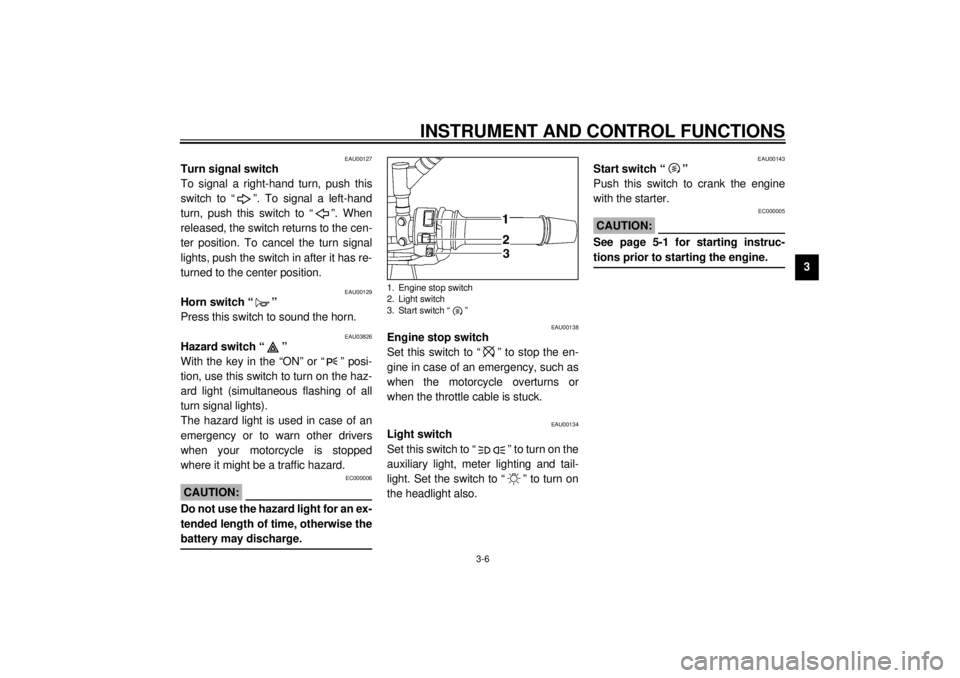
EAU00138
Engine stop switch
Set this switch to “ ” to stop the en-
gine in case of an emergency, such as
when the motorcycle overturns or
when the throttle cable is stuck.
EAU00134
Light switch
Set this switch to “ ” to turn on the
auxiliary light, meter lighting and tail-
light. Set the switch to “ ” to turn on
the headlight also.
EAU00143
Start switch “ ”
Push this switch to crank the engine
with the starter.
EC000005
CAUTION:@ See page 5-1 for starting instruc-
tions prior to starting the engine. @
1. Engine stop switch
2. Light switch
3. Start switch “ ”
E_4tx.book Page 6 Wednesday, October 4, 2000 4:28 PM
Page 106 of 110

10-INDEXAAir filter element, cleaning ...................... 6-15
Anti-theft alarm ........................................3-5BBattery ................................................... 6-34
Brake and clutch levers, checking and
lubricating ............................................ 6-31
Brake and shift pedals, checking and
lubricating ............................................ 6-30
Brake fluid, changing ............................. 6-26
Brake fluid level, checking...................... 6-25
Brake lever...............................................3-7
Brake light switch (rear), adjusting ......... 6-24
Brake pads, checking............................. 6-25
Brake pedal..............................................3-8
Brake pedal position, adjusting .............. 6-23CCables, checking and lubricating............ 6-29
Carburetors, adjusting............................ 6-18
Care.........................................................7-1
Clutch lever ..............................................3-7
Clutch lever free play, adjusting ............. 6-23
Conversion table ......................................8-5
Coolant .................................................. 6-11
Changing .......................................... 6-13
Checking .......................................... 6-11
Coolant temperature warning light............3-2
Cowlings and panels, removing and
installing ................................................6-5
DDimmer switch ......................................... 3-5
Drive chain, lubricating .......................... 6-29
Drive chain slack ................................... 6-27
Adjusting .......................................... 6-27
Checking .......................................... 6-27EEngine break-in ....................................... 5-4
Engine oil and oil filter element ................ 6-9
Engine stop switch................................... 3-6FFront fork, adjusting ............................... 3-13
Front fork, checking ............................... 6-32
Fuel ......................................................... 3-9
Fuel consumption, tips for reducing ......... 5-4
Fuel gauge .............................................. 3-5
Fuel level warning light ............................ 3-3
Fuel tank breather hose
(Germany only) ................................... 3-10
Fuel tank cap ........................................... 3-9
Fuses, replacing .................................... 6-35HHandlebar switches ................................. 3-5
Hazard switch .......................................... 3-6
Headlight bulb, replacing ....................... 6-36
Helmet holder ........................................ 3-11
High beam indicator light ......................... 3-2
Horn switch ............................................. 3-6
IIdentification numbers ..............................9-1
Idling speed, adjusting ...........................6-18
Ignition circuit cut-off system ..................3-18
Indicator and warning lights......................3-2KKey identification number .........................9-1LLight switch ..............................................3-6
Luggage strap holders ...........................3-17MMain switch/steering lock .........................3-1
Model label ..............................................9-2NNeutral indicator light ...............................3-2PParking.....................................................5-5
Part locations ...........................................2-1
Pass switch ..............................................3-5
Periodic maintenance and lubrication
chart ......................................................6-2
Pre-operation check list ............................4-1SSafety information ....................................1-1
Seat .......................................................3-11
Self-diagnosis device ...............................3-4
E_4tx.book Page 1 Wednesday, October 4, 2000 4:28 PM