lights YAMAHA TDM 850 2001 Owners Manual
[x] Cancel search | Manufacturer: YAMAHA, Model Year: 2001, Model line: TDM 850, Model: YAMAHA TDM 850 2001Pages: 110, PDF Size: 12.15 MB
Page 15 of 110
3
INSTRUMENT AND CONTROL FUNCTIONS
Main switch/steering lock ..................................... 3-1
Indicator and warning lights ................................ 3-2
Speedometer unit ................................................ 3-3
Tachometer .......................................................... 3-4
Self-diagnosis device .......................................... 3-4
Anti-theft alarm (optional) .................................... 3-5
Fuel gauge ........................................................... 3-5
Handlebar switches ............................................. 3-5
Clutch lever .......................................................... 3-7
Shift pedal ............................................................ 3-7
Brake lever .......................................................... 3-7
Brake pedal .......................................................... 3-8
Fuel tank cap ....................................................... 3-9Fuel ..................................................................... 3-9
Fuel tank breather hose (for Germany only) ..... 3-10
Starter (choke) lever .......................................... 3-10
Seat ................................................................... 3-11
Helmet holder .................................................... 3-11
Storage compartment ....................................... 3-12
Adjusting the front fork ...................................... 3-13
Adjusting the shock absorber assembly ............ 3-15
Luggage strap holders ...................................... 3-17
Sidestand .......................................................... 3-17
Ignition circuit cut-off system ............................. 3-18
E_4tx.book Page 1 Wednesday, October 4, 2000 4:28 PM
Page 17 of 110
INSTRUMENT AND CONTROL FUNCTIONS
3-2
3
EAU01590
(Parking)
The steering is locked, and the taillight
and auxiliary light are on, but all other
electrical systems are off. The key can
be removed.
The steering must be locked before the
key can be turned to “ ”.
ECA00043
CAUTION:_ Do not use the parking position for
an extended length of time, other-
wise the battery may discharge. _
EAU03034
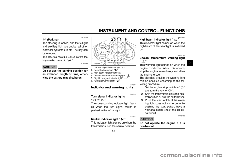
Indicator and warning lights
EAU03299
Turn signal indicator lights
“”/“”
The corresponding indicator light flash-
es when the turn signal switch is
pushed to the left or right.
EAU00061
Neutral indicator light “ ”
This indicator light comes on when the
transmission is in the neutral position.
EAU00063
High beam indicator light “ ”
This indicator light comes on when the
high beam of the headlight is switched
on.
EAU01707
Coolant temperature warning light
“”
This warning light comes on when the
engine overheats. When this occurs,
stop the engine immediately and allow
the engine to cool.
The electrical circuit of the warning light
can be checked according to the fol-
lowing procedure.
1. Set the engine stop switch to “ ”
and turn the key to “ON”.
2. Shift the transmission into the neu-
tral position or pull the clutch lever.
3. Push the start switch. If the warn-
ing light does not come on while
pushing the start switch, have a
Yamaha dealer check the electri-
cal circuit.
EC000002
CAUTION:@ Do not operate the engine if it is
overheated. @
1. Left turn signal indicator light “ ”
2. Neutral indicator light “ ”
3. High beam indicator light “ ”
4. Coolant temperature warning light “ ”
5. Right turn signal indicator light “ ”
6. Fuel level warning light “ ”
E_4tx.book Page 2 Wednesday, October 4, 2000 4:28 PM
Page 21 of 110
INSTRUMENT AND CONTROL FUNCTIONS
3-6
3
EAU00127
Turn signal switch
To signal a right-hand turn, push this
switch to “ ”. To signal a left-hand
turn, push this switch to “ ”. When
released, the switch returns to the cen-
ter position. To cancel the turn signal
lights, push the switch in after it has re-
turned to the center position.
EAU00129
Horn switch “ ”
Press this switch to sound the horn.
EAU03826
Hazard switch “ ”
With the key in the “ON” or “ ” posi-
tion, use this switch to turn on the haz-
ard light (simultaneous flashing of all
turn signal lights).
The hazard light is used in case of an
emergency or to warn other drivers
when your motorcycle is stopped
where it might be a traffic hazard.
EC000006
CAUTION:_ Do not use the hazard light for an ex-
tended length of time, otherwise the
battery may discharge. _
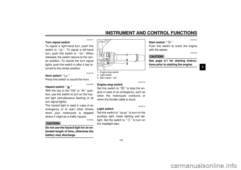
EAU00138
Engine stop switch
Set this switch to “ ” to stop the en-
gine in case of an emergency, such as
when the motorcycle overturns or
when the throttle cable is stuck.
EAU00134
Light switch
Set this switch to “ ” to turn on the
auxiliary light, meter lighting and tail-
light. Set the switch to “ ” to turn on
the headlight also.
EAU00143
Start switch “ ”
Push this switch to crank the engine
with the starter.
EC000005
CAUTION:@ See page 5-1 for starting instruc-
tions prior to starting the engine. @
1. Engine stop switch
2. Light switch
3. Start switch “ ”
E_4tx.book Page 6 Wednesday, October 4, 2000 4:28 PM
Page 37 of 110
PRE-OPERATION CHECKS
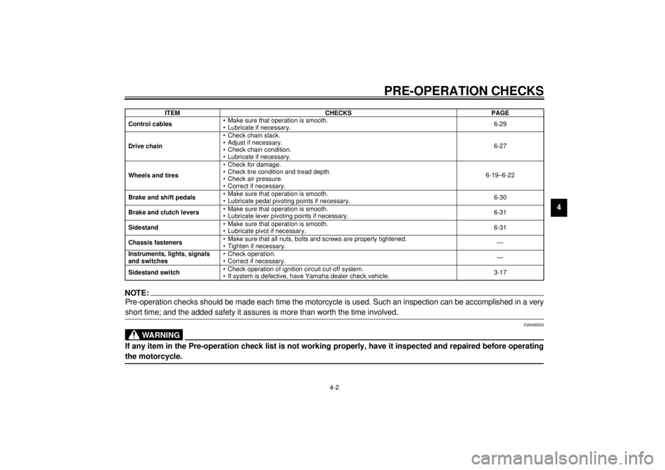
4-2
4
NOTE:_ Pre-operation checks should be made each time the motorcycle is used. Such an inspection can be accomplished in a very
short time; and the added safety it assures is more than worth the time involved. _
EWA00033
WARNING
_ If any item in the Pre-operation check list is not working properly, have it inspected and repaired before operating
the motorcycle. _Control cables• Make sure that operation is smooth.
• Lubricate if necessary.6-29
Drive chain• Check chain slack.
• Adjust if necessary.
• Check chain condition.
• Lubricate if necessary.6-27
Wheels and tires• Check for damage.
• Check tire condition and tread depth.
• Check air pressure.
• Correct if necessary.6-19–6-22
Brake and shift pedals• Make sure that operation is smooth.
• Lubricate pedal pivoting points if necessary.6-30
Brake and clutch levers• Make sure that operation is smooth.
• Lubricate lever pivoting points if necessary.6-31
Sidestand• Make sure that operation is smooth.
• Lubricate pivot if necessary.6-31
Chassis fasteners• Make sure that all nuts, bolts and screws are properly tightened.
• Tighten if necessary.—
Instruments, lights, signals
and switches• Check operation.
• Correct if necessary.—
Sidestand switch• Check operation of ignition circuit cut-off system.
• If system is defective, have Yamaha dealer check vehicle.3-17 ITEM CHECKS PAGE
E_4tx.book Page 2 Wednesday, October 4, 2000 4:28 PM
Page 43 of 110

OPERATION AND IMPORTANT RIDING POINTS
5-4
5
EAU00424
Tips for reducing fuel
consumption Fuel consumption depends largely on
your riding style. Consider the following
tips to reduce fuel consumption:l
Thoroughly warm up the engine.
l
Turn the starter (choke) off as
soon as possible.
l
Shift up swiftly, and avoid high en-
gine speeds during acceleration.
l
Do not rev the engine while shift-
ing down, and avoid high engine
speeds with no load on the engine.
l
Turn the engine off instead of let-
ting it idle for an extended length
of time (e.g., in traffic jams, at traf-
fic lights or at railroad crossings).
EAU00436
Engine break-in There is never a more important period
in the life of your engine than the period
between 0 and 1,000 km. For this rea-
son, you should read the following ma-
terial carefully.
Since the engine is brand new, do not
put an excessive load on it for the first
1,000 km. The various parts in the en-
gine wear and polish themselves to the
correct operating clearances. During
this period, prolonged full-throttle oper-
ation or any condition that might result
in engine overheating must be avoided.
EAU00440*
0–150 kml
Avoid prolonged operation above
5,000 r/min.
l
After every hour of operation, stop
the engine, and then let it cool for
five to ten minutes.
l
Vary the engine speed from time
to time. Do not operate the engine
at one set throttle position.
150–500 km
l
Avoid prolonged operation above
6,000 r/min.
l
Rev the engine freely through the
gears, but do not use full throttle at
any time.
500–1,000 km
l
Avoid prolonged full-throttle oper-
ation.
l
Avoid prolonged operation above
7,000 r/min.
E_4tx.book Page 4 Wednesday, October 4, 2000 4:28 PM
Page 49 of 110
PERIODIC MAINTENANCE AND MINOR REPAIR
6-4
6
EAU03541
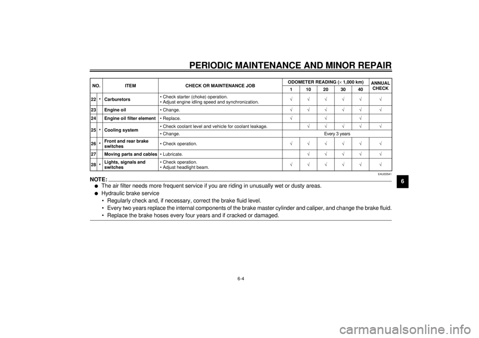
NOTE:_l
The air filter needs more frequent service if you are riding in unusually wet or dusty areas.
l
Hydraulic brake service
• Regularly check and, if necessary, correct the brake fluid level.
• Every two years replace the internal components of the brake master cylinder and caliper, and change the brake fluid.
• Replace the brake hoses every four years and if cracked or damaged.
_22
*Carburetors• Check starter (choke) operation.
• Adjust engine idling speed and synchronization.ÖÖÖÖÖ Ö
23 Engine oil• Change.ÖÖÖÖÖ Ö
24 Engine oil filter element• Replace.ÖÖÖ
25*Cooling system• Check coolant level and vehicle for coolant leakage.ÖÖÖÖ Ö
• Change. Every 3 years
26*Front and rear brake
switches• Check operation.ÖÖÖÖÖ Ö
27 Moving parts and cables• Lubricate.ÖÖÖÖ Ö
28*Lights, signals and
switches• Check operation.
• Adjust headlight beam.ÖÖÖÖÖ Ö NO. ITEM CHECK OR MAINTENANCE JOBODOMETER READING (´1,000 km)
ANNUAL
CHECK
1 10203040
E_4tx.book Page 4 Wednesday, October 4, 2000 4:28 PM
Page 81 of 110
PERIODIC MAINTENANCE AND MINOR REPAIR
6-36
6 3. Turn the key to “ON” and turn on
the electrical circuit in question to
check if the device operates.
4. If the fuse immediately blows
again, have a Yamaha dealer
check the electrical system.
EAU03794
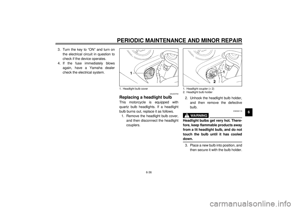
Replacing a headlight bulb This motorcycle is equipped with
quartz bulb headlights. If a headlight
bulb burns out, replace it as follows.
1. Remove the headlight bulb cover,
and then disconnect the headlight
couplers.2. Unhook the headlight bulb holder,
and then remove the defective
bulb.
EW000119
WARNING
_ Headlight bulbs get very hot. There-
fore, keep flammable products away
from a lit headlight bulb, and do not
touch the bulb until it has cooled
down. _3. Place a new bulb into position, and
then secure it with the bulb holder.
1. Headlight bulb cover
1. Headlight coupler (´ 2)
2. Headlight bulb holder
E_4tx.book Page 36 Wednesday, October 4, 2000 4:28 PM
Page 93 of 110
MOTORCYCLE CARE AND STORAGE
7-2
7
l
Do not use any harsh chemical
products on plastic parts. Be
sure to avoid using cloths or
sponges which have been in
contact with strong or abrasive
cleaning products, solvent or
thinner, fuel (gasoline), rust re-
movers or inhibitors, brake flu-
id, antifreeze or electrolyte.
l
Do not use high-pressure wash-
ers or steam-jet cleaners since
they cause water seepage and
deterioration in the following ar-
eas: seals (of wheel and swing-
arm bearings, fork and brakes),
electric components (couplers,
connectors, instruments, switch-
es and lights), breather hoses
and vents.
l
For motorcycles equipped with
a windshield: Do not use strong
cleaners or hard sponges as
they will cause dulling or
scratching. Some cleaning
compounds for plastic may
leave scratches on the wind-
shield. Test the product on a
small hidden part of the wind-
shield to make sure that it does
not leave any marks. If the wind-
shield is scratched, use a quali-
ty plastic polishing compound
after washing.
@
After normal useRemove dirt with warm water, a mild
detergent, and a soft, clean sponge,
and then rinse thoroughly with clean
water. Use a toothbrush or bottlebrush
for hard-to-reach areas. Stubborn dirt
and insects will come off more easily if
the area is covered with a wet cloth for
a few minutes before cleaning.
After riding in the rain, near the sea oron salt-sprayed roadsSince sea salt or salt sprayed on roads
during winter are extremely corrosive in
combination with water, carry out the
following steps after each ride in the
rain, near the sea or on salt-sprayed
roads.NOTE:@ Salt sprayed on roads in the winter may
remain well into spring. @
E_4tx.book Page 2 Wednesday, October 4, 2000 4:28 PM
Page 106 of 110
10-INDEXAAir filter element, cleaning ...................... 6-15
Anti-theft alarm ........................................3-5BBattery ................................................... 6-34
Brake and clutch levers, checking and
lubricating ............................................ 6-31
Brake and shift pedals, checking and
lubricating ............................................ 6-30
Brake fluid, changing ............................. 6-26
Brake fluid level, checking...................... 6-25
Brake lever...............................................3-7
Brake light switch (rear), adjusting ......... 6-24
Brake pads, checking............................. 6-25
Brake pedal..............................................3-8
Brake pedal position, adjusting .............. 6-23CCables, checking and lubricating............ 6-29
Carburetors, adjusting............................ 6-18
Care.........................................................7-1
Clutch lever ..............................................3-7
Clutch lever free play, adjusting ............. 6-23
Conversion table ......................................8-5
Coolant .................................................. 6-11
Changing .......................................... 6-13
Checking .......................................... 6-11
Coolant temperature warning light............3-2
Cowlings and panels, removing and
installing ................................................6-5
DDimmer switch ......................................... 3-5
Drive chain, lubricating .......................... 6-29
Drive chain slack ................................... 6-27
Adjusting .......................................... 6-27
Checking .......................................... 6-27EEngine break-in ....................................... 5-4
Engine oil and oil filter element ................ 6-9
Engine stop switch................................... 3-6FFront fork, adjusting ............................... 3-13
Front fork, checking ............................... 6-32
Fuel ......................................................... 3-9
Fuel consumption, tips for reducing ......... 5-4
Fuel gauge .............................................. 3-5
Fuel level warning light ............................ 3-3
Fuel tank breather hose
(Germany only) ................................... 3-10
Fuel tank cap ........................................... 3-9
Fuses, replacing .................................... 6-35HHandlebar switches ................................. 3-5
Hazard switch .......................................... 3-6
Headlight bulb, replacing ....................... 6-36
Helmet holder ........................................ 3-11
High beam indicator light ......................... 3-2
Horn switch ............................................. 3-6
IIdentification numbers ..............................9-1
Idling speed, adjusting ...........................6-18
Ignition circuit cut-off system ..................3-18
Indicator and warning lights......................3-2KKey identification number .........................9-1LLight switch ..............................................3-6
Luggage strap holders ...........................3-17MMain switch/steering lock .........................3-1
Model label ..............................................9-2NNeutral indicator light ...............................3-2PParking.....................................................5-5
Part locations ...........................................2-1
Pass switch ..............................................3-5
Periodic maintenance and lubrication
chart ......................................................6-2
Pre-operation check list ............................4-1SSafety information ....................................1-1
Seat .......................................................3-11
Self-diagnosis device ...............................3-4
E_4tx.book Page 1 Wednesday, October 4, 2000 4:28 PM
Page 107 of 110
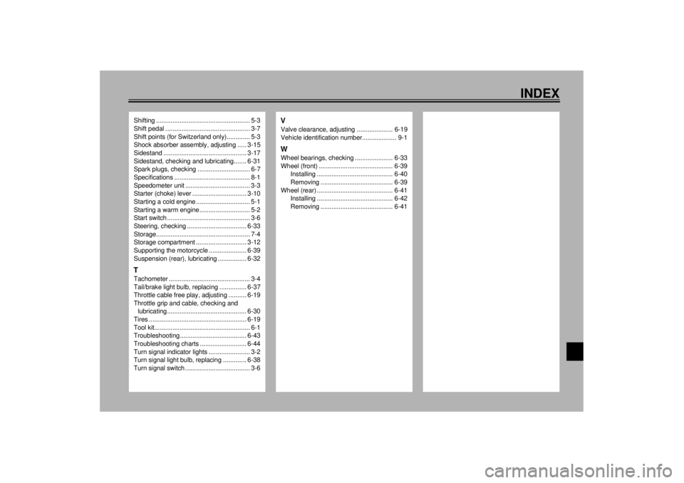
INDEX
Shifting .................................................... 5-3
Shift pedal ............................................... 3-7
Shift points (for Switzerland only)............. 5-3
Shock absorber assembly, adjusting ..... 3-15
Sidestand .............................................. 3-17
Sidestand, checking and lubricating....... 6-31
Spark plugs, checking ............................. 6-7
Specifications .......................................... 8-1
Speedometer unit .................................... 3-3
Starter (choke) lever .............................. 3-10
Starting a cold engine .............................. 5-1
Starting a warm engine ............................ 5-2
Start switch .............................................. 3-6
Steering, checking ................................. 6-33
Storage.................................................... 7-4
Storage compartment ............................ 3-12
Supporting the motorcycle ..................... 6-39
Suspension (rear), lubricating ................ 6-32TTachometer ............................................. 3-4
Tail/brake light bulb, replacing ............... 6-37
Throttle cable free play, adjusting .......... 6-19
Throttle grip and cable, checking and
lubricating............................................ 6-30
Tires ...................................................... 6-19
Tool kit..................................................... 6-1
Troubleshooting..................................... 6-43
Troubleshooting charts .......................... 6-44
Turn signal indicator lights ....................... 3-2
Turn signal light bulb, replacing ............. 6-38
Turn signal switch .................................... 3-6
VValve clearance, adjusting .................... 6-19
Vehicle identification number................... 9-1WWheel bearings, checking ..................... 6-33
Wheel (front) ......................................... 6-39
Installing .......................................... 6-40
Removing ........................................ 6-39
Wheel (rear) .......................................... 6-41
Installing .......................................... 6-42
Removing ........................................ 6-41
E_4tx.book Page 2 Wednesday, October 4, 2000 4:28 PM