torque YAMAHA TDM 850 2001 Owners Manual
[x] Cancel search | Manufacturer: YAMAHA, Model Year: 2001, Model line: TDM 850, Model: YAMAHA TDM 850 2001Pages: 110, PDF Size: 12.15 MB
Page 31 of 110

INSTRUMENT AND CONTROL FUNCTIONS
3-16
3
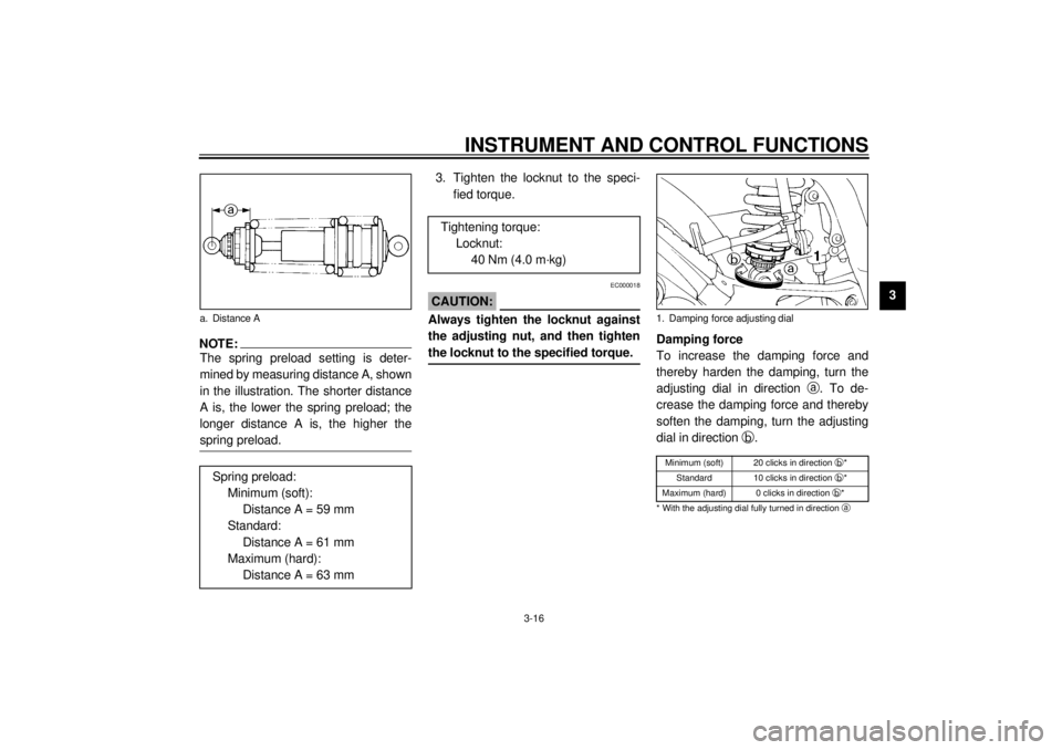
NOTE:_ The spring preload setting is deter-
mined by measuring distance A, shown
in the illustration. The shorter distance
A is, the lower the spring preload; the
longer distance A is, the higher the
spring preload. _
3. Tighten the locknut to the speci-
fied torque.
EC000018
CAUTION:_ Always tighten the locknut against
the adjusting nut, and then tighten
the locknut to the specified torque. _
Damping force
To increase the damping force and
thereby harden the damping, turn the
adjusting dial in direction
a. To de-
crease the damping force and thereby
soften the damping, turn the adjusting
dial in direction
b.CI-04E
a. Distance A
Spring preload:
Minimum (soft):
Distance A = 59 mm
Standard:
Distance A = 61 mm
Maximum (hard):
Distance A = 63 mm
Tightening torque:
Locknut:
40 Nm (4.0 m·kg)
1. Damping force adjusting dialMinimum (soft) 20 clicks in direction
b*
Standard 10 clicks in direction
b*
Maximum (hard) 0 clicks in direction
b*
* With the adjusting dial fully turned in direction
a
E_4tx.book Page 16 Wednesday, October 4, 2000 4:28 PM
Page 46 of 110

6-1
6
EAU00462
6-PERIODIC MAINTENANCE AND MINOR REPAIR
EAU00464
Safety is an obligation of the owner.
Periodic inspection, adjustment and lu-
brication will keep your vehicle in the
safest and most efficient condition pos-
sible. The most important points of in-
spection, adjustment, and lubrication
are explained on the following pages.
The intervals given in the periodic
maintenance and lubrication chart
should be simply considered as a gen-
eral guide under normal riding condi-
tions. However, DEPENDING ON THE
WEATHER, TERRAIN, GEOGRAPHI-
CAL LOCATION, AND INDIVIDUAL
USE, THE MAINTENANCE INTER-
VALS MAY NEED TO BE SHORT-
ENED.
EW000060
WARNING
@ If you are not familiar with motor-
cycle maintenance work, have a
Yamaha dealer do it for you. @
EAU01299
Owner’s tool kit The owner’s tool kit is located inside
the storage compartment under the
seat. (See page 3-11 for seat removal
procedures.)
The service information included in this
manual and the tools provided in the
owner’s tool kit are intended to assist
you in the performance of preventive
maintenance and minor repairs. How-
ever, additional tools such as a torque
wrench may be necessary to perform
certain maintenance work correctly.
NOTE:@ If you do not have the tools or experi-
ence required for a particular job, have
a Yamaha dealer perform it for you. @
EW000063
WARNING
@ Modifications not approved by
Yamaha may cause loss of perfor-
mance and render the vehicle un-
safe for use. Consult a Yamaha
dealer before attempting any chang-
es. @
1. Owner’s tool kit
E_4tx.book Page 1 Wednesday, October 4, 2000 4:28 PM
Page 53 of 110

PERIODIC MAINTENANCE AND MINOR REPAIR
6-8
6 To install a spark plug
1. Measure the spark plug gap with a
wire thickness gauge and, if nec-
essary, adjust the gap to specifica-
tion.
2. Clean the surface of the spark
plug gasket and its mating sur-
face, and then wipe off any grime
from the spark plug threads.
3. Install the spark plug with the
spark plug wrench, and then tight-
en it to the specified torque.
NOTE:@ If a torque wrench is not available when
installing a spark plug, a good estimate
of the correct torque is 1/4–1/2 turn
past finger tight. However, the spark
plug should be tightened to the speci-
fied torque as soon as possible. @4. Install the spark plug cap.
5. Install the cowling.
a. Spark plug gap
Spark plug gap:
0.8–0.9 mm
Tightening torque:
Spark plug:
18 Nm (1.8 m·kg)
E_4tx.book Page 8 Wednesday, October 4, 2000 4:28 PM
Page 55 of 110

PERIODIC MAINTENANCE AND MINOR REPAIR
6-10
6 3. Remove the engine oil tank cap
and drain bolts to drain the oil from
the crankcase.
NOTE:@ Skip steps 4–6 if the oil filter element is
not being replaced. @
4. Remove the oil filter element cover
by removing the bolts.5. Remove and replace the oil filter
element and O-rings.
6. Install the oil filter element cover
by installing the bolts, then tighten-
ing them to the specified torque.
NOTE:@ Make sure that the O-rings are properly
seated.@7. Install the engine oil drain bolts,
and then tighten them to the spec-
ified torques.
1. Engine oil drain bolt A
1. Engine oil drain bolt B
2. Oil filter element cover
3. Bolt (´ 5)
1. Oil filter element
2. O-ring (´ 2)Tightening torque:
Oil filter element cover bolt:
10 Nm (1.0 m·kg)
E_4tx.book Page 10 Wednesday, October 4, 2000 4:28 PM
Page 56 of 110

PERIODIC MAINTENANCE AND MINOR REPAIR
6-11
68. Add the specified amount of the
recommended engine oil, and
then install and tighten the oil tank
cap.
EC000072
CAUTION:@ l
In order to prevent clutch slip-
page (since the engine oil also
lubricates the clutch), do not
mix any chemical additives with
the oil or use oils of a higher
grade than “CD”. In addition, do
not use oils labeled “ENERGY
CONSERVING II” or higher.
l
Make sure that no foreign mate-
rial enters the crankcase.
@9. Start the engine, and then let it idle
for several minutes while checking
it for oil leakage. If oil is leaking,
immediately turn the engine off
and check for the cause.
10. Turn the engine off, and then
check the oil level and correct it if
necessary.
EAU03495
Coolant The coolant level should be checked
before each ride. In addition, the cool-
ant must be changed at the intervals
specified in the periodic maintenance
and lubrication chart.
If the engine overheats, see page 6-45
for further instructions.
To check the coolant level
1. Place the motorcycle on a level
surface and hold it in an upright
position.NOTE:@ l
The coolant level must be checked
on a cold engine since the level
varies with engine temperature.
l
Make sure that the motorcycle is
positioned straight up when
checking the coolant level. A slight
tilt to the side can result in a false
reading.
@
Tightening torques:
Engine oil drain bolt A:
35 Nm (3.5 m·kg)
Engine oil drain bolt B:
30 Nm (3.0 m·kg)
Recommended engine oil:
See page 8-1.
Oil quantity:
Without oil filter element
replacement:
3.5 L
With oil filter element
replacement:
3.6 L
Total amount (dry engine):
4.2 L
E_4tx.book Page 11 Wednesday, October 4, 2000 4:28 PM
Page 59 of 110

PERIODIC MAINTENANCE AND MINOR REPAIR
6-14
6 6. Remove the coolant drain bolts to
drain the cooling system.
7. Remove the coolant reservoir
bolts.
8. Slightly move the coolant reservoir
back, and then disconnect the
hose at the bottom of the coolant
reservoir.
9. Drain the coolant from the coolant
reservoir by opening the cap, then
turning the reservoir upside down.
10. Connect the hose to the coolant
reservoir.
11. Install the coolant reservoir by
placing it in the original position,
then installing the bolts.12. After the coolant is completely
drained, thoroughly flush the cool-
ing system with clean tap water.
13. Install the coolant drain bolts, and
then tighten them to the specified
torque.
NOTE:@ Check the washers for damage and re-
place them if necessary. @14. Pour the recommended coolant
into the radiator until it is full.
1. Coolant drain bolt (´ 2)
1. Coolant reservoir
2. Bolt (´ 2)
3. Clamp
4. Hose
Tightening torque:
Coolant drain bolt:
7 Nm (0.7 m·kg)
E_4tx.book Page 14 Wednesday, October 4, 2000 4:28 PM
Page 73 of 110

PERIODIC MAINTENANCE AND MINOR REPAIR
6-28
6
NOTE:@ Using the alignment marks on each
side of the swingarm, make sure that
both adjusting nuts are in the same po-
sition for proper wheel alignment. @
EC000096
CAUTION:@ Improper drive chain slack will over-
load the engine as well as other vital
parts of the motorcycle and can lead
to chain slippage or breakage. To
prevent this from occurring, keep
the drive chain slack within the
specified limits. @
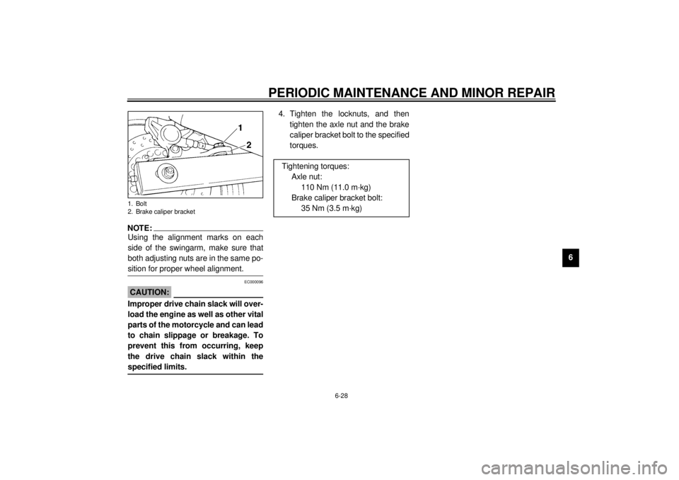
4. Tighten the locknuts, and then
tighten the axle nut and the brake
caliper bracket bolt to the specified
torques.
1. Bolt
2. Brake caliper bracket
Tightening torques:
Axle nut:
110 Nm (11.0 m·kg)
Brake caliper bracket bolt:
35 Nm (3.5 m·kg)
E_4tx.book Page 28 Wednesday, October 4, 2000 4:28 PM
Page 85 of 110

PERIODIC MAINTENANCE AND MINOR REPAIR
6-40
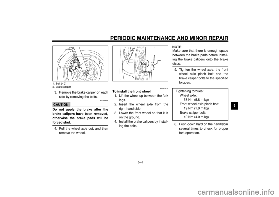
6 3. Remove the brake caliper on each
side by removing the bolts.
ECA00046
CAUTION:@ Do not apply the brake after the
brake calipers have been removed,
otherwise the brake pads will be
forced shut. @4. Pull the wheel axle out, and then
remove the wheel.
EAU03829
To install the front wheel
1. Lift the wheel up between the fork
legs.
2. Insert the wheel axle from the
right-hand side.
3. Lower the front wheel so that it is
on the ground.
4. Install the brake calipers by install-
ing the bolts.
NOTE:_ Make sure that there is enough space
between the brake pads before install-
ing the brake calipers onto the brake
discs. _5. Tighten the wheel axle, the front
wheel axle pinch bolt and the
brake caliper bolts to the specified
torques.
6. Push down hard on the handlebar
several times to check for proper
fork operation.
1. Bolt (´ 2)
2. Brake caliper
Tightening torques:
Wheel axle:
58 Nm (5.8 m·kg)
Front wheel axle pinch bolt:
19 Nm (1.9 m·kg)
Brake caliper bolt:
40 Nm (4.0 m·kg)
E_4tx.book Page 40 Wednesday, October 4, 2000 4:28 PM
Page 87 of 110

PERIODIC MAINTENANCE AND MINOR REPAIR
6-42
6 5. Loosen the locknut on each side of
the swingarm.
6. Turn the drive chain slack adjust-
ing nuts fully in direction
a.7. Push the wheel forward, and then
remove the drive chain from the
rear sprocket.
NOTE:_ The drive chain does not need to be
disassembled in order to remove and
install the rear wheel. _8. Remove the axle nut.
9. Pull the wheel axle out, and then
remove the wheel.
EAU03501
To install the rear wheel
1. Install the wheel by inserting the
wheel axle from the right-hand
side.
2. Install the drive chain onto the rear
sprocket, and then adjust the drive
chain slack. (See page 6-27 for
drive chain slack adjustment pro-
cedures.)
3. Install the brake caliper by install-
ing the bolts.
4. Install the axle nut, and then lower
the rear wheel so that it is on the
ground.
5. Tighten the axle nut, the brake cal-
iper bolts and the brake caliper
bracket bolt to the specified
torques.
1. Locknut
2. Drive chain slack adjusting nut
Tightening torques:
Axle nut:
110 Nm (11.0 m·kg)
Brake caliper bolt:
40 Nm (4.0 m·kg)
Brake caliper bracket bolt:
35 Nm (3.5 m·kg)
E_4tx.book Page 42 Wednesday, October 4, 2000 4:28 PM
Page 102 of 110

SPECIFICATIONS
8-5
8
EAU01064
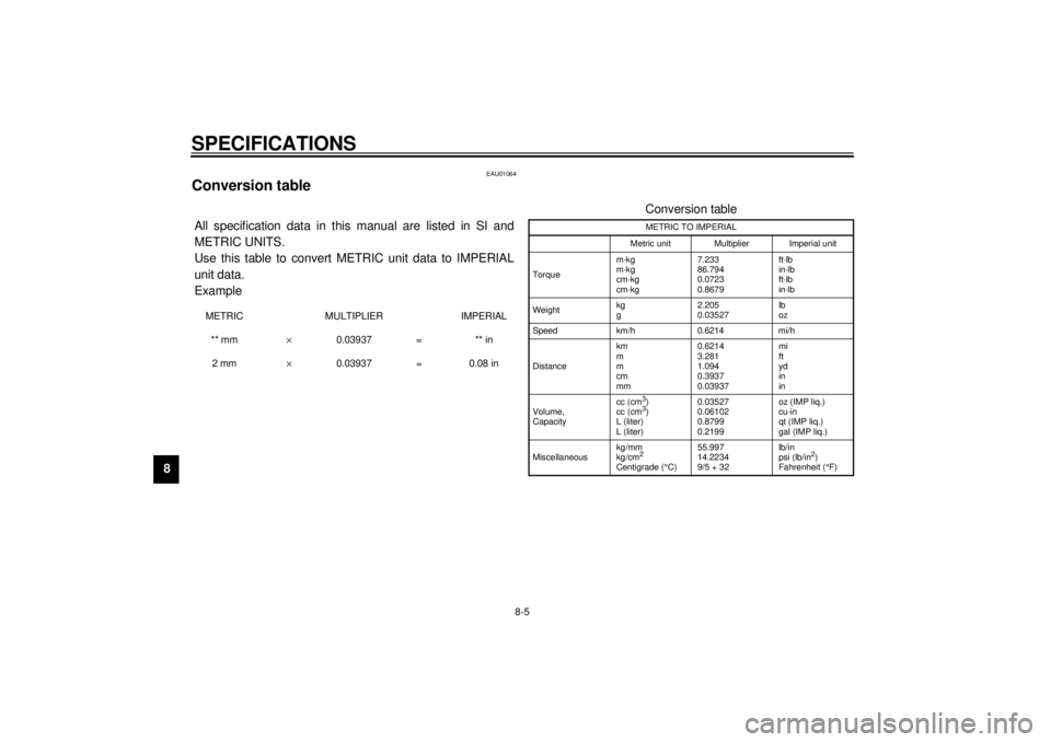
Conversion table CS-02EAll specification data in this manual are listed in SI and
METRIC UNITS.
Use this table to convert METRIC unit data to IMPERIAL
unit data.
ExampleMETRIC MULTIPLIER IMPERIAL
** mm´ 0.03937 = ** in
2 mm´ 0.03937 = 0.08 in
Conversion tableMETRIC TO IMPERIAL
Metric unit Multiplier Imperial unit
Torquem·kg
m·kg
cm·kg
cm·kg7.233
86.794
0.0723
0.8679ft·lb
in·lb
ft·lb
in·lb
Weightkg
g2.205
0.03527lb
oz
Speed km/h 0.6214 mi/h
Distancekm
m
m
cm
mm0.6214
3.281
1.094
0.3937
0.03937mi
ft
yd
in
in
Volume,
Capacitycc (cm3)
cc (cm3)
L (liter)
L (liter)0.03527
0.06102
0.8799
0.2199oz (IMP liq.)
cu·in
qt (IMP liq.)
gal (IMP liq.)
Miscellaneouskg/mm
kg/cm2
Centigrade (°
C)55.997
14.2234
9/5 + 32 lb/in
psi (lb/in
2)
Fahrenheit (°
F)
E_4tx.book Page 5 Wednesday, October 4, 2000 4:28 PM