bulb YAMAHA TDM 900 2002 Owners Manual
[x] Cancel search | Manufacturer: YAMAHA, Model Year: 2002, Model line: TDM 900, Model: YAMAHA TDM 900 2002Pages: 110, PDF Size: 4.79 MB
Page 45 of 110

6
PERIODIC MAINTENANCE AND MINOR REPAIR
Owner’s tool kit .................................................... 6-1
Periodic maintenance and lubrication chart ......... 6-2
Removing and installing cowlings and panels ..... 6-5
Checking the spark plugs .................................... 6-7
Engine oil and oil filter element ............................ 6-9
Coolant .............................................................. 6-12
Cleaning the air filter element ............................ 6-16
Adjusting the engine idling speed ...................... 6-17
Adjusting the throttle cable free play .................. 6-18
Adjusting the valve clearance ............................ 6-18
Tires ................................................................... 6-19
Adjusting the clutch lever free play .................... 6-22
Adjusting the brake pedal position ..................... 6-23
Adjusting the rear brake light switch .................. 6-23
Checking the front and rear brake pads ............. 6-24
Checking the brake fluid level ............................ 6-25
Changing the brake fluid .................................... 6-26
Drive chain slack ................................................ 6-26
Lubricating the drive chain ................................. 6-28
Checking and lubricating the cables .................. 6-28Checking and lubricating the throttle grip and
cable ............................................................... 6-29
Checking and lubricating the brake and
shift pedals ...................................................... 6-29
Checking and lubricating the brake and
clutch levers .................................................... 6-29
Checking and lubricating the sidestand ............ 6-30
Lubricating the rear suspension ........................ 6-30
Checking the front fork ...................................... 6-31
Checking the steering ....................................... 6-31
Checking the wheel bearings ............................ 6-32
Battery ............................................................... 6-33
Replacing the fuses .......................................... 6-34
Replacing a headlight bulb ................................ 6-35
Replacing a tail/brake light bulb ........................ 6-36
Replacing a turn signal light bulb ...................... 6-37
Supporting the motorcycle ................................ 6-37
Front wheel ....................................................... 6-38
Rear wheel ........................................................ 6-39
Troubleshooting ................................................. 6-42
Troubleshooting charts ...................................... 6-43
U5PSE0.book Page 1 Thursday, December 13, 2001 4:29 PM
Page 80 of 110

PERIODIC MAINTENANCE AND MINOR REPAIR
6-35
63. Turn the key to “ON” and turn on
the electrical circuit in question to
check if the device operates.
4. If the fuse immediately blows
again, have a Yamaha dealer
check the electrical system.
EAU04136*
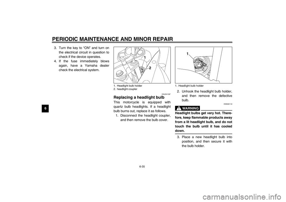
Replacing a headlight bulb This motorcycle is equipped with
quartz bulb headlights. If a headlight
bulb burns out, replace it as follows.
1. Disconnect the headlight coupler,
and then remove the bulb cover.2. Unhook the headlight bulb holder,
and then remove the defective
bulb.
EW000119
WARNING
_ Headlight bulbs get very hot. There-
fore, keep flammable products away
from a lit headlight bulb, and do not
touch the bulb until it has cooled
down. _3. Place a new headlight bulb into
position, and then secure it with
the bulb holder.
1. Headlight bulb holder
2. headlight coupler
1. Headlight bulb holder
U5PSE0.book Page 35 Thursday, December 13, 2001 4:29 PM
Page 81 of 110

PERIODIC MAINTENANCE AND MINOR REPAIR
6-36
6
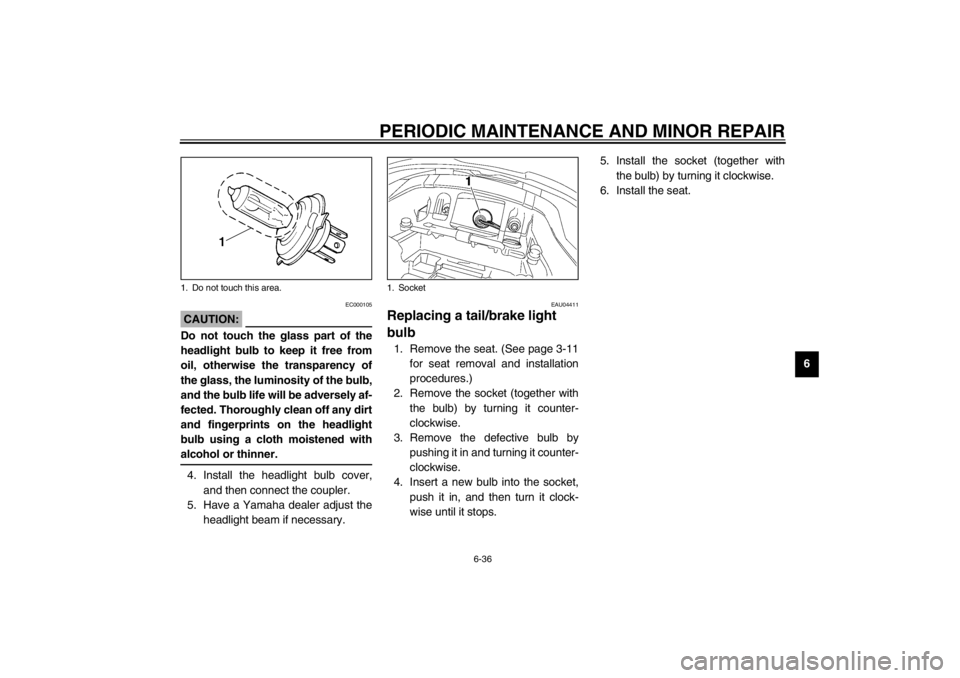
EC000105
CAUTION:_ Do not touch the glass part of the
headlight bulb to keep it free from
oil, otherwise the transparency of
the glass, the luminosity of the bulb,
and the bulb life will be adversely af-
fected. Thoroughly clean off any dirt
and fingerprints on the headlight
bulb using a cloth moistened with
alcohol or thinner. _4. Install the headlight bulb cover,
and then connect the coupler.
5. Have a Yamaha dealer adjust the
headlight beam if necessary.
EAU04411
Replacing a tail/brake light
bulb 1. Remove the seat. (See page 3-11
for seat removal and installation
procedures.)
2. Remove the socket (together with
the bulb) by turning it counter-
clockwise.
3. Remove the defective bulb by
pushing it in and turning it counter-
clockwise.
4. Insert a new bulb into the socket,
push it in, and then turn it clock-
wise until it stops.5. Install the socket (together with
the bulb) by turning it clockwise.
6. Install the seat.
1. Do not touch this area.
1. Socket
U5PSE0.book Page 36 Thursday, December 13, 2001 4:29 PM
Page 82 of 110

PERIODIC MAINTENANCE AND MINOR REPAIR
6-37
6
EAU03497
Replacing a turn signal light
bulb 1. Remove the turn signal light lens
by removing the screw.
2. Remove the defective bulb by
pushing it in and turning it counter-
clockwise.3. Insert a new bulb into the socket,
push it in, and then turn it clock-
wise until it stops.
4. Install the lens by installing the
screw.
ECA00065
CAUTION:@ Do not overtighten the screw, other-
wise the lens may break. @
EAU01579
Supporting the motorcycle Since this model is not equipped with a
centerstand, follow these precautions
when removing the front and rear
wheel or performing other mainte-
nance requiring the motorcycle to
stand upright. Check that the motor-
cycle is in a stable and level position
before starting any maintenance. A
strong wooden box can be placed un-
der the engine for added stability.
To service the front wheel
1. Stabilize the rear of the motorcycle
by using a motorcycle stand or, if
an additional motorcycle stand is
not available, by placing a jack un-
der the frame in front of the rear
wheel.
2. Raise the front wheel off the
ground by using a motorcycle
stand.
1. Screw
2. Turn signal light lens
1. Turn signal light bulb
U5PSE0.book Page 37 Thursday, December 13, 2001 4:29 PM
Page 101 of 110

SPECIFICATIONS
8-4
8
Electrical system
Ignition system T.C.I. (digital)
Charging system
Type A.C. magneto
Standard output 14 V, 31.5 A @ 5,000 r/min
Battery
Model GT12B-4
Voltage, capacity 12 V, 10 Ah
Headlight typeQuar tz bulb (halogen)
Bulb voltage, wattage × quantity
Headlight 12 V, 55 W × 2
Auxiliary light 12 V, 5 W × 1
Tail/brake light 12 V, 5/21 W × 2
Turn signal light 12 V, 10 W × 4
Meter lighting 12 V, 2 W × 2
Neutral indicator light 14 V, 1.2 W × 1
High beam indicator light 14 V, 1.4 W × 1
Turn signal indicator light 14 V, 1.2 W × 2
Oil level warning light L.E.D.
Engine trouble warning light 14 V, 1.4 W × 1Fuses
Main fuse 40 A
Headlight fuse 15 A
Signaling system fuse 7.5 A
Ignition fuse 10 A
Parking lighting fuse 5 A
Turn signal and hazard light
fuse 10 A
Backup fuse (odometer and
clock) 5 A
Radiator fan fuse 20 A
Electronic Fuel Injection
System fuse 10 A
U5PSE0.book Page 4 Thursday, December 13, 2001 4:29 PM
Page 106 of 110

10-INDEXAAir filter element, cleaning ...................... 6-16
Anti-theft alarm ........................................3-6BBattery ................................................... 6-33
Brake and clutch levers, checking and
lubricating ............................................ 6-29
Brake and shift pedals, checking and
lubricating ............................................ 6-29
Brake fluid, changing ............................. 6-26
Brake fluid level, checking...................... 6-25
Brake lever...............................................3-8
Brake light switch (rear), adjusting ......... 6-23
Brake pads, checking............................. 6-24
Brake pedal..............................................3-8
Brake pedal position, adjusting .............. 6-23CCables, checking and lubricating............ 6-28
Care.........................................................7-1
Clutch lever ..............................................3-7
Clutch lever free play, adjusting ............. 6-22
Conversion table ......................................8-5
Coolant .................................................. 6-12
Changing .......................................... 6-13
Checking .......................................... 6-12
Coolant temperature gauge .....................3-5
Cowlings and panels, removing and
installing ................................................6-5DDimmer switch .........................................3-6
Drive chain, lubricating ........................... 6-28
Drive chain slack ................................... 6-26
Adjusting .......................................... 6-27
Checking .......................................... 6-26EEngine break-in ....................................... 5-4
Engine oil and oil filter element ................ 6-9
Engine stop switch................................... 3-7
Engine trouble warning light .................... 3-3FFront fork, adjusting ............................... 3-13
Front fork, checking ............................... 6-31
Fuel ......................................................... 3-9
Fuel consumption, tips for reducing ......... 5-4
Fuel level warning symbol ....................... 3-2
Fuel tank breather hose
(Germany only) ................................... 3-10
Fuel tank cap ........................................... 3-9
Fuses, replacing .................................... 6-34HHandlebar switches ................................. 3-6
Hazard switch .......................................... 3-6
Headlight bulb, replacing ....................... 6-35
High beam indicator light ......................... 3-2
Horn switch ............................................. 3-6IIdentification numbers ............................. 9-1
Idling speed, adjusting ........................... 6-17
Ignition circuit cut-off system.................. 3-18
Indicator and warning lights ..................... 3-2
KKey identification number .........................9-1LLight switch ..............................................3-7
Luggage strap holders ...........................3-17MMain switch/steering lock .........................3-1
Model label ..............................................9-2NNeutral indicator light ...............................3-2OOil level warning light ...............................3-3PParking.....................................................5-5
Part locations ...........................................2-1
Pass switch ..............................................3-6
Periodic maintenance and lubrication
chart ......................................................6-2
Pre-operation check list ............................4-1RRear suspension, lubricating ..................6-30SSafety information ....................................1-1
Seat .......................................................3-11
Shifting .....................................................5-3
Shift pedal ................................................3-8
Shift points (for Switzerland only) .............5-3
Shock absorber assembly, adjusting ......3-15
Sidestand ...............................................3-17
U5PSE0.book Page 1 Thursday, December 13, 2001 4:29 PM
Page 107 of 110

INDEX
Sidestand, checking and lubricating....... 6-30
Spark plugs, checking ............................. 6-7
Specifications .......................................... 8-1
Speedometer unit .................................... 3-3
Starting the engine .................................. 5-1
Start switch .............................................. 3-7
Steering, checking ................................. 6-31
Storage.................................................... 7-4
Storage compartment ............................ 3-11
Supporting the motorcycle ..................... 6-37TTachometer unit ...................................... 3-5
Tail/brake light bulb, replacing ............... 6-36
Throttle cable free play, adjusting .......... 6-18
Throttle grip and cable, checking and
lubricating............................................ 6-29
Tires ...................................................... 6-19
Tool kit..................................................... 6-1
Troubleshooting..................................... 6-42
Troubleshooting charts .......................... 6-43
Turn signal indicator lights ....................... 3-2
Turn signal light bulb, replacing ............. 6-37
Turn signal switch .................................... 3-6VValve clearance, adjusting ..................... 6-18
Vehicle identification number ................... 9-1WWheel bearings, checking...................... 6-32
Wheel (front).......................................... 6-38
Installing........................................... 6-39
Removing......................................... 6-38
Wheel (rear) .......................................... 6-39
Installing .......................................... 6-41
Removing ........................................ 6-39
U5PSE0.book Page 2 Thursday, December 13, 2001 4:29 PM