ABS YAMAHA TDR 125 2000 Owners Manual
[x] Cancel search | Manufacturer: YAMAHA, Model Year: 2000, Model line: TDR 125, Model: YAMAHA TDR 125 2000Pages: 104, PDF Size: 4.88 MB
Page 13 of 104
DESCRIPTION
1
2
3
4
5
6
7
8
9
2-2
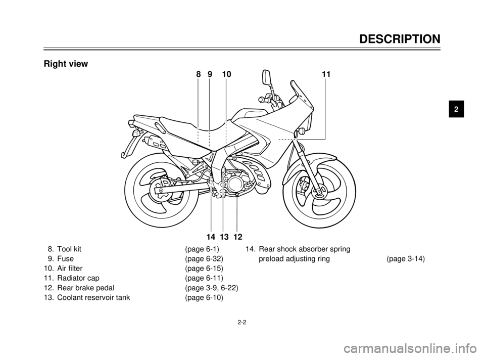
8. Tool kit (page 6-1)
9. Fuse (page 6-32)
10. Air filter (page 6-15)
11. Radiator cap (page 6-11)
12. Rear brake pedal (page 3-9, 6-22)
13. Coolant reservoir tank (page 6-10)14. Rear shock absorber spring
preload adjusting ring (page 3-14)
8 9 10 11
12
13 14
Right view
5AE-9-E3 (ENG) 4/11/0 11:06 AM Page 11
Page 15 of 104
INSTRUMENT AND CONTROL FUNCTIONS
Main switch/steering lock........................................3-1
Indicator lights ........................................................3-2
Oil level indicator circuit check ...............................3-3
Speedometer ..........................................................3-4
Tachometer ............................................................3-4
Engine temperature gauge .....................................3-5
Handlebar switches ................................................3-5
Headlight beam variation ........................................3-6
Clutch lever.............................................................3-8
Shift pedal...............................................................3-8
Front brake lever ....................................................3-8
Rear brake pedal ....................................................3-9
Fuel tank cap ..........................................................3-9
Fuel.......................................................................3-10
Catalyzer (for Switzerland and Austria) ................3-11
Two-stroke engine oil ...........................................3-12
Fuel cock ..............................................................3-12
Starter (choke) “1” ..............................................3-13
Seat ......................................................................3-13
Helmet holder .......................................................3-14
Rear shock absorber adjustment..........................3-14
Note on handling of the Yamaha Energy
Induction System (Y.E.I.S.) ..................................3-15Y.P.V.S. (Yamaha Power Valve System) .............3-16
Sidestand..............................................................3-16
Sidestand/clutch switch operation check ..............3-17
3
5AE-9-E3 (ENG) 4/11/0 11:06 AM Page 13
Page 29 of 104
3-14
INSTRUMENT AND CONTROL FUNCTIONS
1
2
3
4
5
6
7
8
9
EAU00260Helmet holder
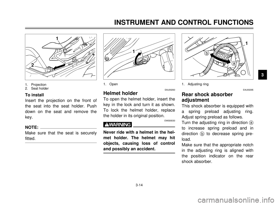
To open the helmet holder, insert the
key in the lock and turn it as shown.
To lock the helmet holder, replace
the holder in its original position.
EW000030
w
Never ride with a helmet in the hel-
met holder. The helmet may hit
objects, causing loss of control
and possibly an accident.
EAU00295
Rear shock absorber
adjustment
This shock absorber is equipped with
a spring preload adjusting ring.
Adjust spring preload as follows.
Turn the adjusting ring in direction a
to increase spring preload and in
direction bto decrease spring pre-
load.
Make sure that the appropriate notch
in the adjusting ring is aligned with
the position indicator on the rear
shock absorber. To install
Insert the projection on the front of
the seat into the seat holder. Push
down on the seat and remove the
key.
NOTE:
Make sure that the seat is securely
fitted.
1
2
1. Projection
2. Seat holder
1
1. Open
a
b1
1. Adjusting ring
5AE-9-E3 (ENG) 4/11/0 11:06 AM Page 27
Page 30 of 104
3-15
1
2
3
4
5
6
7
8
9
1
2
1
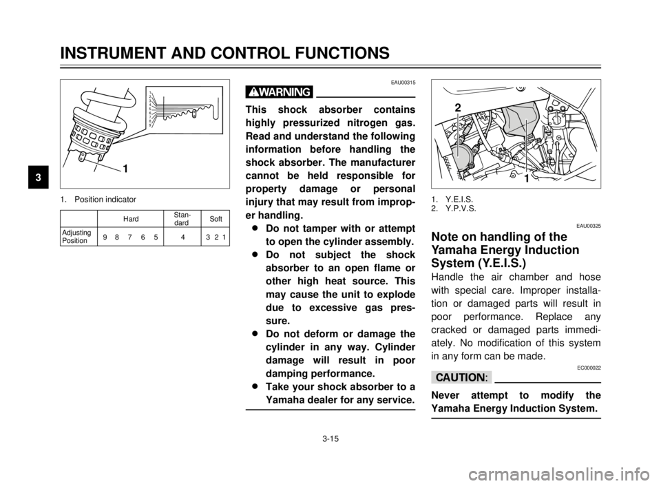
1. Position indicator1. Y.E.I.S.
2. Y.P.V.S.
EAU00315
w
This shock absorber contains
highly pressurized nitrogen gas.
Read and understand the following
information before handling the
shock absorber. The manufacturer
cannot be held responsible for
property damage or personal
injury that may result from improp-
er handling.
8 8
Do not tamper with or attempt
to open the cylinder assembly.
8 8
Do not subject the shock
absorber to an open flame or
other high heat source. This
may cause the unit to explode
due to excessive gas pres-
sure.
8 8
Do not deform or damage the
cylinder in any way. Cylinder
damage will result in poor
damping performance.
8 8
Take your shock absorber to a
Yamaha dealer for any service.
EAU00325
Note on handling of the
Yamaha Energy Induction
System (Y.E.I.S.)
Handle the air chamber and hose
with special care. Improper installa-
tion or damaged parts will result in
poor performance. Replace any
cracked or damaged parts immedi-
ately. No modification of this system
in any form can be made.
EC000022
cC
Never attempt to modify the
Yamaha Energy Induction System.
INSTRUMENT AND CONTROL FUNCTIONS
1
2
3
4
5
6
7
8
9
HardStan-
Softdard
Adjusting
98 7 6 5 4 321
Position
5AE-9-E3 (ENG) 4/11/0 11:06 AM Page 28
Page 49 of 104

6-4
PERIODIC MAINTENANCE AND MINOR REPAIR
6
EVERY
6,000 km 12,000 km
No.
ITEM CHECKS AND MAINTENANCE JOBS
Initialor or
(1,000 km)6 months 12 months
(Whichever (Whichever
comes first) comes first)
9Check swingarm pivoting point for play.
10 * Swingarm9Correct if necessary.
ÖÖ
9Lubricate with lithium soap base grease every
24,000 km or 24 months (whichever comes first).
9Check chain slack.
11 Drive chain9
Adjust if necessary. Make sure that the rear wheel is properly aligned.Every 1,000 km and after washing
9Clean and lubricate.the motorcycle or riding in the rain
9Check bearing play and steering for roughness.
12 * Steering bearings9Correct accordingly.
ÖÖ
9Lubricate with lithium soap base grease every 24,000 km or
24 months (whichever comes first).
13 * Chassis fasteners9
Make sure that all nuts, bolts and screws are properly tightened.ÖÖ9Tighten if necessary.
14 Sidestand9Check operation.
ÖÖ
9Lubricate and repair if necessary.
15 * Sidestand switch9Check operation.
ÖÖÖ
9Replace if necessary.
16 * Front fork9Check operation and for oil leakage.
ÖÖ
9Correct accordingly.
17 *Rear shock absorber9Check operation and shock absorber for oil leakage.
ÖÖ
assembly9Replace shock absorber assembly if necessary.
Rear shock absorber9Check operation.
18 * assembly pivoting9Lubricate with lithium grease every 24,000 km ÖÖ
pointsor 24 months (whichever comes first).
19 * Carburetor9Check engine idling speed and starter operation.
ÖÖÖ
9Adjust if necessary.
5AE-9-E3 (ENG) 4/11/0 11:06 AM Page 47
Page 88 of 104
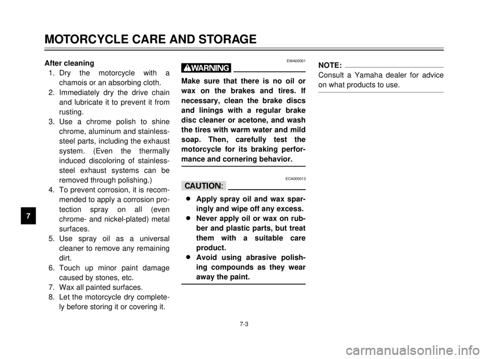
After cleaning
1. Dry the motorcycle with a
chamois or an absorbing cloth.
2. Immediately dry the drive chain
and lubricate it to prevent it from
rusting.
3. Use a chrome polish to shine
chrome, aluminum and stainless-
steel parts, including the exhaust
system. (Even the thermally
induced discoloring of stainless-
steel exhaust systems can be
removed through polishing.)
4. To prevent corrosion, it is recom-
mended to apply a corrosion pro-
tection spray on all (even
chrome- and nickel-plated) metal
surfaces.
5. Use spray oil as a universal
cleaner to remove any remaining
dirt.
6. Touch up minor paint damage
caused by stones, etc.
7. Wax all painted surfaces.
8. Let the motorcycle dry complete-
ly before storing it or covering it.EWA00001
w
Make sure that there is no oil or
wax on the brakes and tires. If
necessary, clean the brake discs
and linings with a regular brake
disc cleaner or acetone, and wash
the tires with warm water and mild
soap. Then, carefully test the
motorcycle for its braking perfor-
mance and cornering behavior.
ECA000013
cC
8
8
Apply spray oil and wax spar-
ingly and wipe off any excess.
8 8
Never apply oil or wax on rub-
ber and plastic parts, but treat
them with a suitable care
product.
8 8
Avoid using abrasive polish-
ing compounds as they wear
away the paint.
NOTE:
Consult a Yamaha dealer for advice
on what products to use.
MOTORCYCLE CARE AND STORAGE
7-3
7
5AE-9-E3 (ENG) 4/11/0 11:06 AM Page 86
Page 94 of 104

SPECIFICATIONS
1
2
3
4
5
6
7
8
9
Wheels
Front
Type Cast wheel
Size 18 ´MT2.15
Rear
Type Cast wheel
Size 17 ´MT2.50
Brakes
Front
Type Single disc brake
Operation Right hand operation
Fluid DOT 3 or DOT 4
Rear
Type Single disc brake
Operation Right foot operation
Fluid DOT 4
Suspension
Front
Type Telescopic fork
Rear
Type Swingarm (Monocross)Shock absorber
Front
Type Coil spring/oil damper
Rear
Type Coil-gas spring/oil damper
Wheel travel
Front 180 mm
Rear 180 mm
Electrical
Ignition system C.D.I.
Charging system
Type C.D.I. magneto
Standard output 14 V, 12A @5,000 r/min
Battery
Type YTX5L-BS
Voltage, capacity 12 V, 4 AH
Headlight bulb typeHalogen bulb
Bulb voltage, wattage ´quantity
Headlight 12 V, 60/55W ´2
12 V, 35/35W ´2 (GB, IRL only)
8-3
5AE-9-E3 (ENG) 4/11/0 11:06 AM Page 92
Page 100 of 104
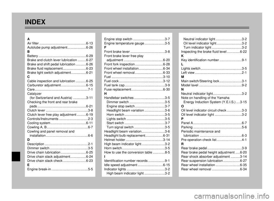
INDEX
Engine stop switch ..................................3-7
Engine temperature gauge ......................3-5
F
Front brake lever .....................................3-8
Front brake lever free play
adjustment ..........................................6-20
Front fork inspection ..............................6-28
Front wheel installation..........................6-34
Front wheel removal ..............................6-33
Fuel .......................................................3-10
Fuel cock ...............................................3-12
Fuel tank cap ...........................................3-9
Fuse replacement..................................6-30
H
Handlebar switches .................................3-5
Dimmer switch ......................................3-5
Engine stop switch ................................3-7
Headlight beam variation ......................3-6
Horn switch ...........................................3-5
Lights switch .........................................3-5
Start switch ...........................................3-7
Turn signal switch .................................3-5
Headlight beam variation.........................3-6
Headlight bulb replacement...................6-31
Helmet holder ........................................3-14
High beam indicator light .........................3-2
Horn switch..............................................3-5
How to use the conversion table .............8-5
I
Identification number records ..................9-1
Idle speed adjustment ...........................6-15
Indicator lights .........................................3-2
High beam indicator light ......................3-2Neutral indicator light ............................3-2
Oil level indicator light ...........................3-2
Turn indicator light ................................3-2
Inspecting the brake fluid level ..............6-22
K
Key identification number ........................9-1
L
Lights switch ............................................3-5
Left view ..................................................2-1
M
Main switch/Steering lock ........................3-1
Model lavel ..............................................9-2
N
Neutral indicator light...............................3-2
Note on handling of the Yamaha
Energy Induction System (Y.E.I.S.) ....3-15
O
Oil level indicator circuit check ................3-3
Oil level indicator light .............................3-2
P
Panel A ....................................................6-7
Parking ....................................................5-6
Periodic maintenance and
lubrication .............................................6-3
Pre-operation check list ...........................4-1
R
Rear brake pedal .....................................3-9
Rear brake pedal height adjustment .....6-20
Rear shock absorber adjustment ..........3-14
Rear suspension lubrication ..................6-27
Rear wheel installation ..........................6-35
Rear wheel removal ..............................6-34A
Air filter ..................................................6-13
Autolube pump adjustment....................6-26
B
Battery ...................................................6-29
Brake and clutch lever lubrication .........6-27
Brake and shift pedal lubrication ...........6-26
Brake fluid replacement.........................6-23
Brake light switch adjustment ................6-21
C
Cable inspection and lubrication ...........6-25
Carburetor adjustment...........................6-15
Care.........................................................7-1
Catalyzer
(for Switzerland and Austria) ..............3-11
Checking the front and rear brake
pads ....................................................6-21
Clutch lever .............................................3-8
Clutch lever free play adjustment ..........6-19
Controls/Instruments ...............................2-3
Cooling system ......................................6-11
Cowling A, B ............................................6-7
Cowling and panel removal and
installation .............................................6-6
D
Description ..............................................2-1
Dimmer switch .........................................3-5
Drive chain lubrication ...........................6-25
Drive chain slack adjustment.................6-24
Drive chain slack check .........................6-23
E
Engine break-in .......................................5-5
5AE-9-E3 (ENG) 4/11/0 11:06 AM Page 98