bulb YAMAHA TDR 125 2000 Owners Manual
[x] Cancel search | Manufacturer: YAMAHA, Model Year: 2000, Model line: TDR 125, Model: YAMAHA TDR 125 2000Pages: 104, PDF Size: 4.88 MB
Page 21 of 104
3-6
INSTRUMENT AND CONTROL FUNCTIONS
1
2
3
4
5
6
7
8
9
1
2&
&%
%
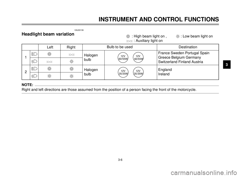
Left RightBulb to be used
Destination
3
'
3
2
'
2
3
2
Halogen
bulb
Halogen
bulbFrance Sweden Portugal Spain
Greece Belgium Germany
Switzerland Finland Austria
England
Ireland 3 : High beam light on , 2: Low beam light on
': Auxiliary light on
12V
60/55W12V
60/55W
12V
35/35W12V
35/35W
EAU00136
Headlight beam variation
NOTE:
Right and left directions are those assumed from the position of a person facing the front of the motorcycle.
5AE-9-E3 (ENG) 4/11/0 11:06 AM Page 19
Page 45 of 104
PERIODIC MAINTENANCE AND MINOR REPAIR
Tool kit ...................................................................6-1
Periodic maintenance and lubrication ....................6-3
Cowling and panel removal and installation...........6-6
Cowling A, B ..........................................................6-7
Panel A ..................................................................6-7
Spark plug inspection.............................................6-8
Transmission oil .....................................................6-9
Cooling system ....................................................6-10
Changing the coolant ...........................................6-11
Air filter .................................................................6-13
Carburetor adjustment .........................................6-15
Idle speed adjustment ..........................................6-15
Throttle cable free play adjustment ......................6-16
Tires .....................................................................6-17
Wheels .................................................................6-19
Clutch lever free play adjustment.........................6-19
Front brake lever free play adjustment ................6-20
Rear brake pedal height adjustment ....................6-20
Brake light switch adjustment ..............................6-21
Checking the front and rear brake pads...............6-21
Inspecting the brake fluid level.............................6-22
Brake fluid replacement .......................................6-23
Drive chain slack check .......................................6-23
Drive chain slack adjustment ...............................6-24Drive chain lubrication............................................6-25
Cable inspection and lubrication ............................6-25
Throttle cable and grip lubrication ..........................6-26
Autolube pump adjustment ....................................6-26
Brake and shift pedal lubrication ............................6-26
Brake and clutch lever lubrication ..........................6-27
Sidestand lubrication..............................................6-27
Rear suspension lubrication...................................6-27
Front fork inspection ..............................................6-28
Steering inspection ................................................6-28
Wheel bearings ......................................................6-29
Battery....................................................................6-29
Fuse replacement ..................................................6-30
Headlight bulb replacement ...................................6-31
Taillight bulb replacement ......................................6-32
Turn signal light bulb replacement .........................6-32
Front wheel removal ..............................................6-33
Front wheel installation ..........................................6-34
Rear wheel removal ...............................................6-34
Rear wheel installation ...........................................6-35
Troubleshooting .....................................................6-36
Troubleshooting chart ............................................6-37
6
5AE-9-E3 (ENG) 4/11/0 11:06 AM Page 43
Page 76 of 104
6-31
PERIODIC MAINTENANCE AND MINOR REPAIR
1
2
3
4
5
6
7
8
9
2
1
2
1
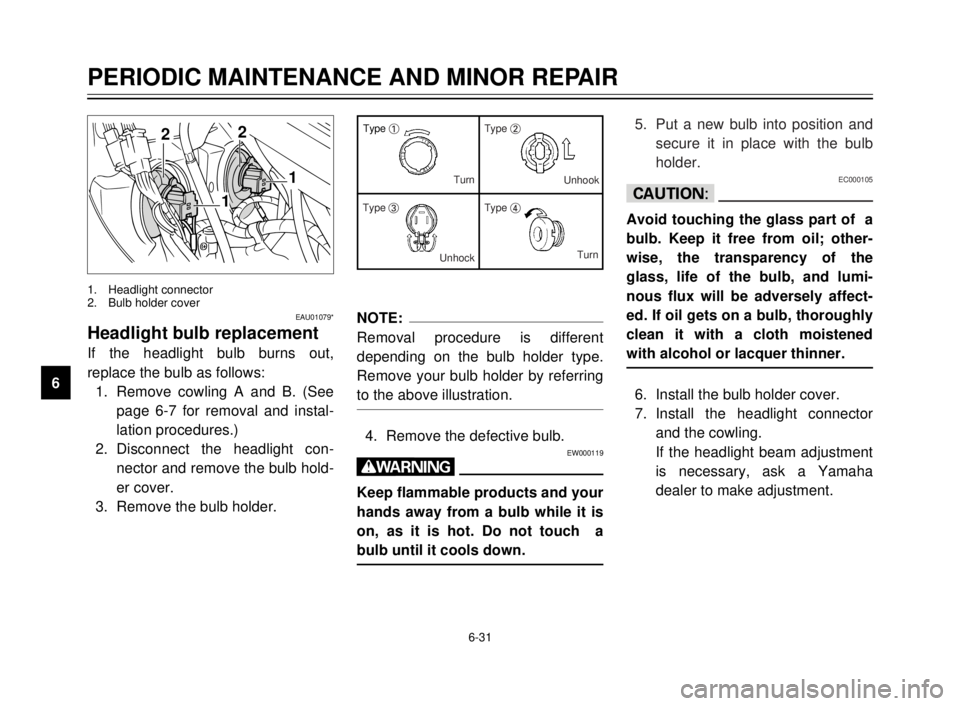
1. Headlight connector
2. Bulb holder cover
EAU01079*
Headlight bulb replacement
If the headlight bulb burns out,
replace the bulb as follows:
1. Remove cowling A and B. (See
page 6-7 for removal and instal-
lation procedures.)
2. Disconnect the headlight con-
nector and remove the bulb hold-
er cover.
3. Remove the bulb holder.
NOTE:
Removal procedure is different
depending on the bulb holder type.
Remove your bulb holder by referring
to the above illustration.
4. Remove the defective bulb.EW000119
w
Keep flammable products and your
hands away from a bulb while it is
on, as it is hot. Do not touch a
bulb until it cools down.
Type 1Type 2
Type 3Type 4 Turn
Unhook
UnhockTurn5. Put a new bulb into position and
secure it in place with the bulb
holder.
EC000105
cC
Avoid touching the glass part of a
bulb. Keep it free from oil; other-
wise, the transparency of the
glass, life of the bulb, and lumi-
nous flux will be adversely affect-
ed. If oil gets on a bulb, thoroughly
clean it with a cloth moistened
with alcohol or lacquer thinner.
6. Install the bulb holder cover.
7. Install the headlight connector
and the cowling.
If the headlight beam adjustment
is necessary, ask a Yamaha
dealer to make adjustment.
5AE-9-E3 (ENG) 4/11/0 11:06 AM Page 74
Page 77 of 104
6-32
PERIODIC MAINTENANCE AND MINOR REPAIR
1
2
3
4
5
6
7
8
9
12
EAU01078
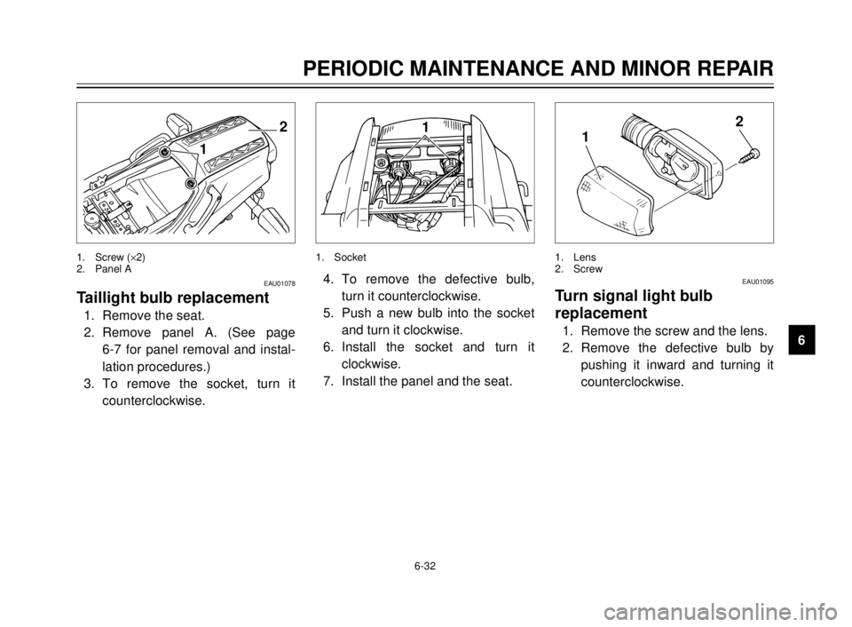
Taillight bulb replacement
1. Remove the seat.
2. Remove panel A. (See page
6-7 for panel removal and instal-
lation procedures.)
3. To remove the socket, turn it
counterclockwise.
1. Screw (´2)
2. Panel A
1
4. To remove the defective bulb,
turn it counterclockwise.
5. Push a new bulb into the socket
and turn it clockwise.
6. Install the socket and turn it
clockwise.
7. Install the panel and the seat.
1. Socket
12
EAU01095
Turn signal light bulb
replacement
1. Remove the screw and the lens.
2. Remove the defective bulb by
pushing it inward and turning it
counterclockwise.
1. Lens
2. Screw
5AE-9-E3 (ENG) 4/11/0 11:06 AM Page 75
Page 78 of 104
6-33
PERIODIC MAINTENANCE AND MINOR REPAIR
1
2
3
4
5
6
7
8
9
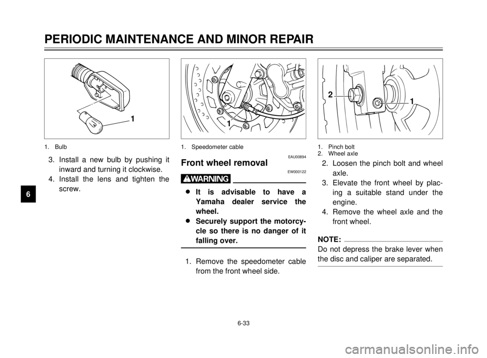
1
1. Speedometer cable
EAU00894Front wheel removalEW000122
w
8 8
It is advisable to have a
Yamaha dealer service the
wheel.
8 8
Securely support the motorcy-
cle so there is no danger of it
falling over.
1. Remove the speedometer cable
from the front wheel side.
2
1
1. Pinch bolt
2. Wheel axle
2. Loosen the pinch bolt and wheel
axle.
3. Elevate the front wheel by plac-
ing a suitable stand under the
engine.
4. Remove the wheel axle and the
front wheel.
NOTE:
Do not depress the brake lever when
the disc and caliper are separated.
1
1. Bulb
3. Install a new bulb by pushing it
inward and turning it clockwise.
4. Install the lens and tighten the
screw.
5AE-9-E3 (ENG) 4/11/0 11:06 AM Page 76
Page 94 of 104
SPECIFICATIONS
1
2
3
4
5
6
7
8
9
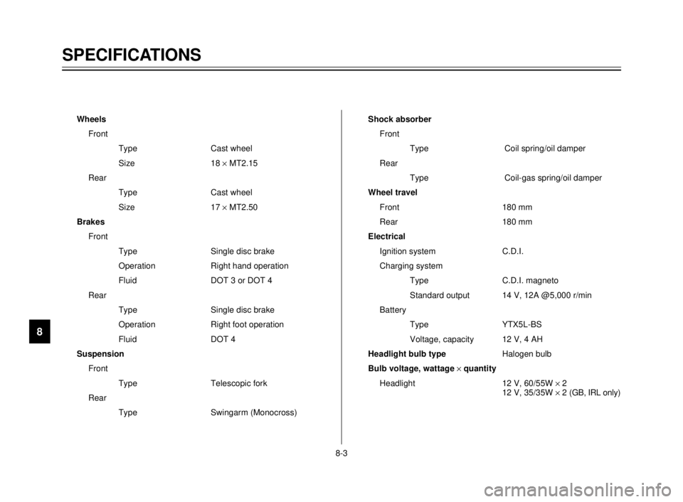
Wheels
Front
Type Cast wheel
Size 18 ´MT2.15
Rear
Type Cast wheel
Size 17 ´MT2.50
Brakes
Front
Type Single disc brake
Operation Right hand operation
Fluid DOT 3 or DOT 4
Rear
Type Single disc brake
Operation Right foot operation
Fluid DOT 4
Suspension
Front
Type Telescopic fork
Rear
Type Swingarm (Monocross)Shock absorber
Front
Type Coil spring/oil damper
Rear
Type Coil-gas spring/oil damper
Wheel travel
Front 180 mm
Rear 180 mm
Electrical
Ignition system C.D.I.
Charging system
Type C.D.I. magneto
Standard output 14 V, 12A @5,000 r/min
Battery
Type YTX5L-BS
Voltage, capacity 12 V, 4 AH
Headlight bulb typeHalogen bulb
Bulb voltage, wattage ´quantity
Headlight 12 V, 60/55W ´2
12 V, 35/35W ´2 (GB, IRL only)
8-3
5AE-9-E3 (ENG) 4/11/0 11:06 AM Page 92
Page 100 of 104
INDEX
Engine stop switch ..................................3-7
Engine temperature gauge ......................3-5
F
Front brake lever .....................................3-8
Front brake lever free play
adjustment ..........................................6-20
Front fork inspection ..............................6-28
Front wheel installation..........................6-34
Front wheel removal ..............................6-33
Fuel .......................................................3-10
Fuel cock ...............................................3-12
Fuel tank cap ...........................................3-9
Fuse replacement..................................6-30
H
Handlebar switches .................................3-5
Dimmer switch ......................................3-5
Engine stop switch ................................3-7
Headlight beam variation ......................3-6
Horn switch ...........................................3-5
Lights switch .........................................3-5
Start switch ...........................................3-7
Turn signal switch .................................3-5
Headlight beam variation.........................3-6
Headlight bulb replacement...................6-31
Helmet holder ........................................3-14
High beam indicator light .........................3-2
Horn switch..............................................3-5
How to use the conversion table .............8-5
I
Identification number records ..................9-1
Idle speed adjustment ...........................6-15
Indicator lights .........................................3-2
High beam indicator light ......................3-2Neutral indicator light ............................3-2
Oil level indicator light ...........................3-2
Turn indicator light ................................3-2
Inspecting the brake fluid level ..............6-22
K
Key identification number ........................9-1
L
Lights switch ............................................3-5
Left view ..................................................2-1
M
Main switch/Steering lock ........................3-1
Model lavel ..............................................9-2
N
Neutral indicator light...............................3-2
Note on handling of the Yamaha
Energy Induction System (Y.E.I.S.) ....3-15
O
Oil level indicator circuit check ................3-3
Oil level indicator light .............................3-2
P
Panel A ....................................................6-7
Parking ....................................................5-6
Periodic maintenance and
lubrication .............................................6-3
Pre-operation check list ...........................4-1
R
Rear brake pedal .....................................3-9
Rear brake pedal height adjustment .....6-20
Rear shock absorber adjustment ..........3-14
Rear suspension lubrication ..................6-27
Rear wheel installation ..........................6-35
Rear wheel removal ..............................6-34A
Air filter ..................................................6-13
Autolube pump adjustment....................6-26
B
Battery ...................................................6-29
Brake and clutch lever lubrication .........6-27
Brake and shift pedal lubrication ...........6-26
Brake fluid replacement.........................6-23
Brake light switch adjustment ................6-21
C
Cable inspection and lubrication ...........6-25
Carburetor adjustment...........................6-15
Care.........................................................7-1
Catalyzer
(for Switzerland and Austria) ..............3-11
Checking the front and rear brake
pads ....................................................6-21
Clutch lever .............................................3-8
Clutch lever free play adjustment ..........6-19
Controls/Instruments ...............................2-3
Cooling system ......................................6-11
Cowling A, B ............................................6-7
Cowling and panel removal and
installation .............................................6-6
D
Description ..............................................2-1
Dimmer switch .........................................3-5
Drive chain lubrication ...........................6-25
Drive chain slack adjustment.................6-24
Drive chain slack check .........................6-23
E
Engine break-in .......................................5-5
5AE-9-E3 (ENG) 4/11/0 11:06 AM Page 98
Page 101 of 104
INDEX
Recommended shift points
(for Switzerland only) ............................5-5
Right view ................................................2-2
S
Seat .......................................................3-13
Shift pedal ...............................................3-8
Shifting ....................................................5-4
Sidestand ..............................................3-16
Sidestand lubrication .............................6-27
Sidestand/clutch switch operation
check ..................................................3-17
Spark plug inspection ..............................6-8
Specifications ..........................................8-1
Speedometer ...........................................3-4
Start switch ..............................................3-7
Starter (choke) “1” ...............................3-13
Starting a warm engine ...........................5-4
Starting the engine ..................................5-1
Steering inspection ................................6-28
Storage ....................................................7-4
T
Tachometer .............................................3-4
Taillight bulb replacement .....................6-32
Throttle cable and grip lubrication .........6-25
Throttle cable free play adjustment .......6-16
Tips for reducing fuel consumption .........5-5
Tires ......................................................6-17
Tool kit .....................................................6-1
Transmission oil ......................................6-9
Troubleshooting.....................................6-36
Troubleshooting chart............................6-37
Turn indicator light ...................................3-2
Turn signal light bulb replacement ........6-32Turn signal switch....................................3-5
Two-stroke engine oil ............................3-12
V
Vehicle identification number ..................9-1
W
Wheel bearings .....................................6-29
Wheels ..................................................6-19
Y
Y.P.V.S.
(Yamaha Power Valve System) ..........3-16
5AE-9-E3 (ENG) 4/11/0 11:06 AM Page 99