seat YAMAHA TDR 125 2000 Owners Manual
[x] Cancel search | Manufacturer: YAMAHA, Model Year: 2000, Model line: TDR 125, Model: YAMAHA TDR 125 2000Pages: 104, PDF Size: 4.88 MB
Page 10 of 104
1-1
Motorcycles are fascinating vehicles, which can give you an unsurpassed feeling of power and free-
dom. However, they also impose certain limits, which you must accept; even the best motorcycle
does not ignore the laws of physics.
Regular care and maintenance are essential for preserving your motorcycle’s value and operating
condition. Moreover, what is true for the motorcycle is also true for the rider: good performance
depends on being in good shape. Riding under the influence of medication, drugs and alcohol is, of
course, out of the question. Motorcycle riders more than car drivers must always be at their mental
and physical best. Under the influence of even small amounts of alcohol, there is a tendency to take
dangerous risks.
Protective clothing is as essential for the motorcycle rider as seat belts are for car drivers and passen-
gers. Always wear a complete motorcycle suit (whether made of leather or tear-resistant synthetic
materials with protectors), sturdy boots, motorcycle gloves and a properly fitting helmet. Optimum pro-
tective wear, however, should not encourage carelessness. Though full-coverage helmets and suits,
in particular, create an illusion of total safety and protection, motorcyclists will always be vulnerable.
Riders who lack critical self-control run the risk of going too fast and are apt to take chances. This is
even more dangerous in wet weather. The good motorcyclist rides safely, predictably and defensively
avoiding all dangers, including those caused by others.
Enjoy your ride!
EAU00021
QGIVE SAFETY THE RIGHT OF WAY
1
2
3
4
5
6
7
8
9
5AE-9-E3 (ENG) 4/11/0 11:06 AM Page 8
Page 15 of 104
INSTRUMENT AND CONTROL FUNCTIONS
Main switch/steering lock........................................3-1
Indicator lights ........................................................3-2
Oil level indicator circuit check ...............................3-3
Speedometer ..........................................................3-4
Tachometer ............................................................3-4
Engine temperature gauge .....................................3-5
Handlebar switches ................................................3-5
Headlight beam variation ........................................3-6
Clutch lever.............................................................3-8
Shift pedal...............................................................3-8
Front brake lever ....................................................3-8
Rear brake pedal ....................................................3-9
Fuel tank cap ..........................................................3-9
Fuel.......................................................................3-10
Catalyzer (for Switzerland and Austria) ................3-11
Two-stroke engine oil ...........................................3-12
Fuel cock ..............................................................3-12
Starter (choke) “1” ..............................................3-13
Seat ......................................................................3-13
Helmet holder .......................................................3-14
Rear shock absorber adjustment..........................3-14
Note on handling of the Yamaha Energy
Induction System (Y.E.I.S.) ..................................3-15Y.P.V.S. (Yamaha Power Valve System) .............3-16
Sidestand..............................................................3-16
Sidestand/clutch switch operation check ..............3-17
3
5AE-9-E3 (ENG) 4/11/0 11:06 AM Page 13
Page 28 of 104
1
a
b1
RES
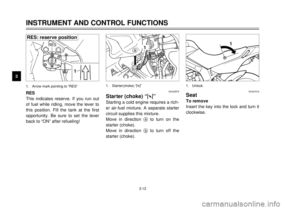
This indicates reserve. If you run out
of fuel while riding, move the lever to
this position. Fill the tank at the first
opportunity. Be sure to set the lever
back to “ON” after refueling!EAU02976
Starter (choke) “1”
Starting a cold engine requires a rich-
er air-fuel mixture. A separate starter
circuit supplies this mixture.
Move in direction ato turn on the
starter (choke).
Move in direction bto turn off the
starter (choke).
EAU01619Seat
To remove
Insert the key into the lock and turn it
clockwise.
1. Starter(choke) “1” 1. Unlock
3-13
INSTRUMENT AND CONTROL FUNCTIONS
1
2
3
4
5
6
7
8
9
1
RES
1. Arrow mark pointing to “RES”
RES: reserve position
5AE-9-E3 (ENG) 4/11/0 11:06 AM Page 26
Page 29 of 104
3-14
INSTRUMENT AND CONTROL FUNCTIONS
1
2
3
4
5
6
7
8
9
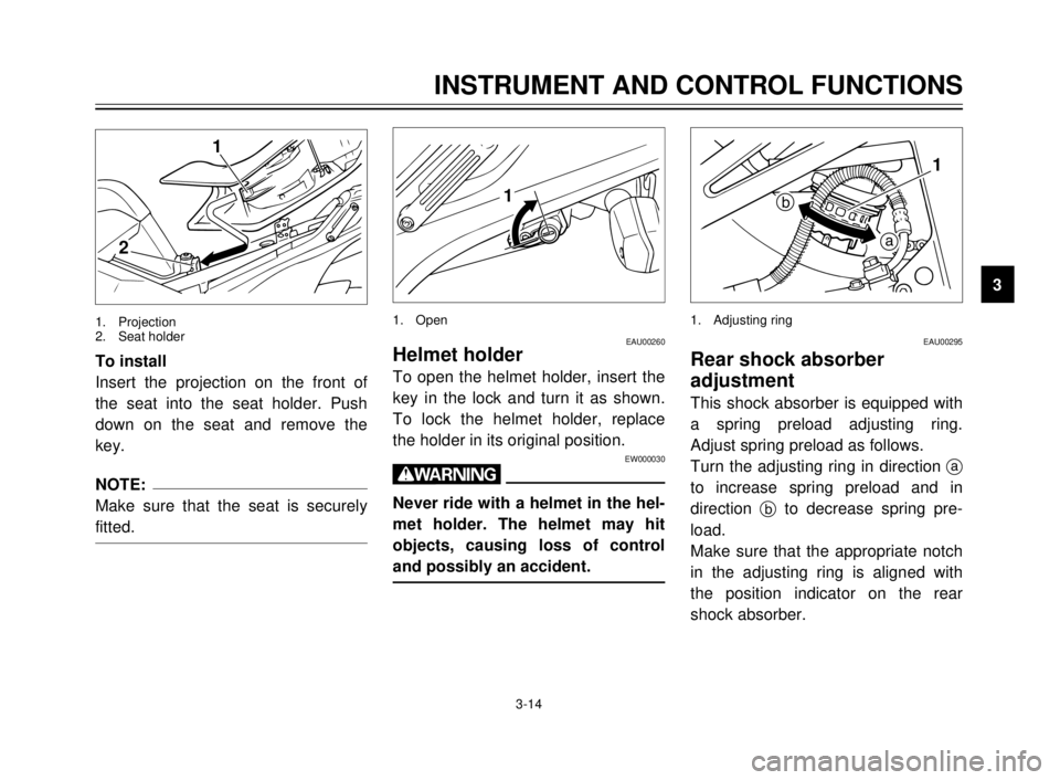
EAU00260Helmet holder
To open the helmet holder, insert the
key in the lock and turn it as shown.
To lock the helmet holder, replace
the holder in its original position.
EW000030
w
Never ride with a helmet in the hel-
met holder. The helmet may hit
objects, causing loss of control
and possibly an accident.
EAU00295
Rear shock absorber
adjustment
This shock absorber is equipped with
a spring preload adjusting ring.
Adjust spring preload as follows.
Turn the adjusting ring in direction a
to increase spring preload and in
direction bto decrease spring pre-
load.
Make sure that the appropriate notch
in the adjusting ring is aligned with
the position indicator on the rear
shock absorber. To install
Insert the projection on the front of
the seat into the seat holder. Push
down on the seat and remove the
key.
NOTE:
Make sure that the seat is securely
fitted.
1
2
1. Projection
2. Seat holder
1
1. Open
a
b1
1. Adjusting ring
5AE-9-E3 (ENG) 4/11/0 11:06 AM Page 27
Page 52 of 104
6-7
2
1
1
12
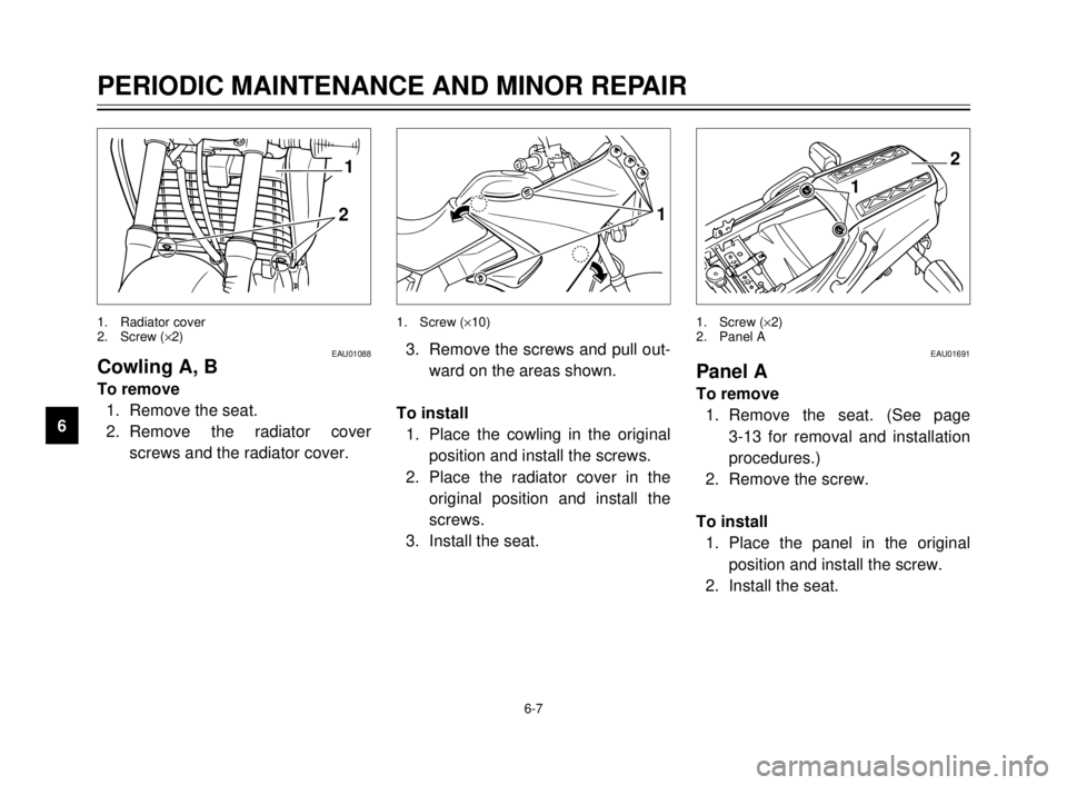
EAU01088Cowling A, B
To remove
1. Remove the seat.
2. Remove the radiator cover
screws and the radiator cover.
1. Radiator cover
2. Screw (´2)1. Screw (´10) 1. Screw (´2)
2. Panel A
3. Remove the screws and pull out-
ward on the areas shown.
To install
1. Place the cowling in the original
position and install the screws.
2. Place the radiator cover in the
original position and install the
screws.
3. Install the seat.EAU01691
Panel A
To remove
1. Remove the seat. (See page
3-13 for removal and installation
procedures.)
2. Remove the screw.
To install
1. Place the panel in the original
position and install the screw.
2. Install the seat.
PERIODIC MAINTENANCE AND MINOR REPAIR
1
2
3
4
5
6
7
8
9
5AE-9-E3 (ENG) 4/11/0 11:06 AM Page 50
Page 56 of 104
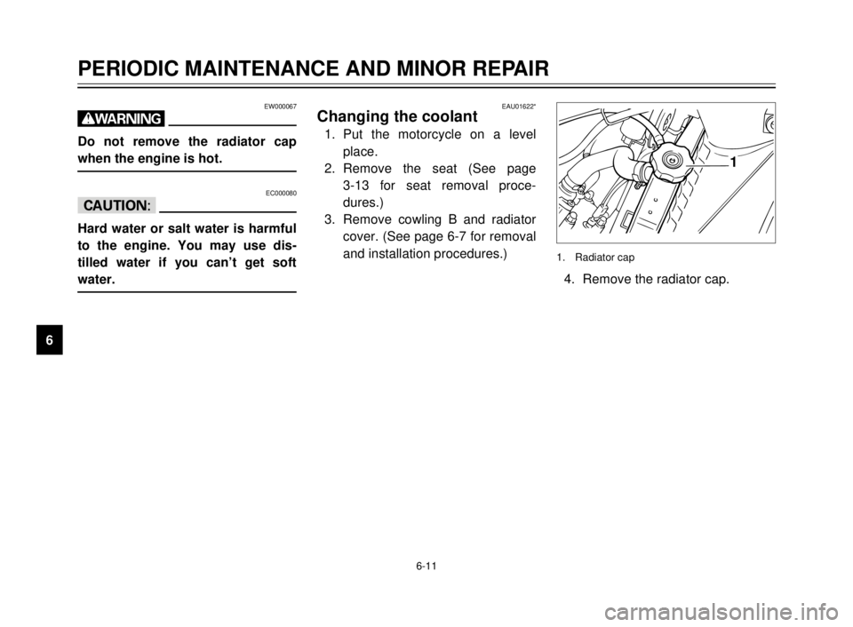
EAU01622*Changing the coolant
1. Put the motorcycle on a level
place.
2. Remove the seat (See page
3-13 for seat removal proce-
dures.)
3. Remove cowling B and radiator
cover. (See page 6-7 for removal
and installation procedures.)
6-11
PERIODIC MAINTENANCE AND MINOR REPAIR
1
2
3
4
5
6
7
8
94. Remove the radiator cap.
EW000067
w
Do not remove the radiator cap
when the engine is hot.
EC000080
cC
Hard water or salt water is harmful
to the engine. You may use dis-
tilled water if you can’t get soft
water.
1
1. Radiator cap
5AE-9-E3 (ENG) 4/11/0 11:06 AM Page 54
Page 58 of 104
6-13
PERIODIC MAINTENANCE AND MINOR REPAIR
1
2
3
4
5
6
7
8
9
2
1
4
5
3
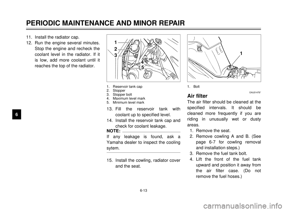
1. Reservoir tank cap
2. Stopper
3. Stopper bolt
4. Maximum level mark
5. Minimum level mark
11. Install the radiator cap.
12. Run the engine several minutes.
Stop the engine and recheck the
coolant level in the radiator. If it
is low, add more coolant until it
reaches the top of the radiator.
13. Fill the reservoir tank with
coolant up to specified level.
14. Install the reservoir tank cap and
check for coolant leakage.
NOTE:
If any leakage is found, ask a
Yamaha dealer to inspect the cooling
sytem.
15. Install the cowling, radiator cover
and the seat.
1
EAU01476*Air filter
The air filter should be cleaned at the
specified intervals. It should be
cleaned more frequently if you are
riding in unusually wet or dusty
areas.
1. Remove the seat.
2. Remove cowling A and B. (See
page 6-7 for cowling removal
and installation steps.)
3. Remove the fuel tank bolt.
4. Lift the front of the fuel tank
upward and position it away from
the air filter case. (Do not
remove the fuel hoses.)
1. Bolt
5AE-9-E3 (ENG) 4/11/0 11:06 AM Page 56
Page 60 of 104
6-15
PERIODIC MAINTENANCE AND MINOR REPAIR
1
2
3
4
5
6
7
8
9
EC000082
cC
8
8
Make sure the air filter is prop-
erly seated in the air filter
case.
8 8
The engine should never be
run without the air filter
installed. Excessive piston
and/or cylinder wear may
result.
EW000131
w
Make sure that the fuel hoses and
vacuum hose are properly con-
nected, in place and not pinched. If
a hose is damaged, be sure to
replace it.
EAU00629Carburetor adjustment
The carburetor is a vital part of the
engine and requires very sophisticat-
ed adjustment. Most adjustments
should be left to a Yamaha dealer
who has the professional knowledge
and experience to do so. However,
the following may be serviced by the
owner as part of routine mainte-
nance.
EC000094
cC
The carburetor was set at the
Yamaha factory after many tests. If
the settings are changed, poor
engine performance and damage
may result.
ba
1
EAU00632Idle speed adjustment
1. Start the engine and warm it up
for a few minutes at approxi-
mately 1,000 to 2,000 r/min.
Occasionally rev the engine to
4,000 to 5,000 r/min. The engine
is warm when it quickly responds
to the throttle.
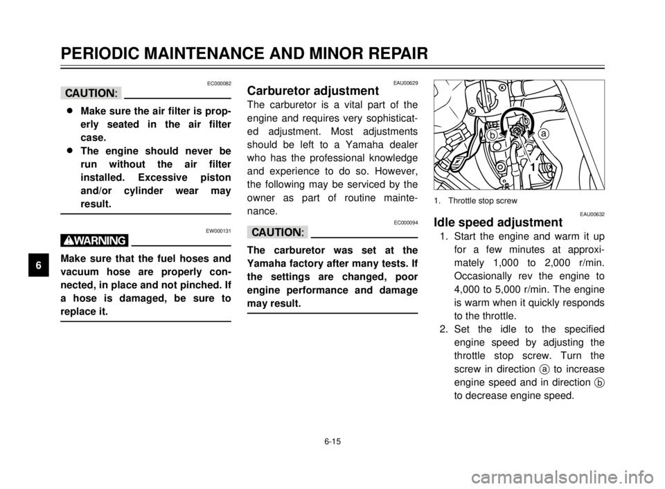
2. Set the idle to the specified
engine speed by adjusting the
throttle stop screw. Turn the
screw in direction ato increase
engine speed and in direction b
to decrease engine speed.
1. Throttle stop screw
5AE-9-E3 (ENG) 4/11/0 11:06 AM Page 58
Page 75 of 104
6-30
PERIODIC MAINTENANCE AND MINOR REPAIR
1
2
3
4
5
6
7
8
9 Battery storage
When the motorcycle is not used for
a month or longer, remove the bat-
tery, fully charge it and store it in a
cool, dry place.
EC000102
cC
8
8
Completely recharge the bat-
tery before storing. Storing a
discharged battery can cause
permanent battery damage.
8 8
Use a battery charger
designed for a sealed-type
(MF) battery. Using a conven-
tional battery charger will
cause battery damage. If you
do not have a sealed-type bat-
tery charger, contact your
Yamaha dealer.
8 8
Always make sure the connec-
tions are correct when rein-
stalling the battery.
1
2
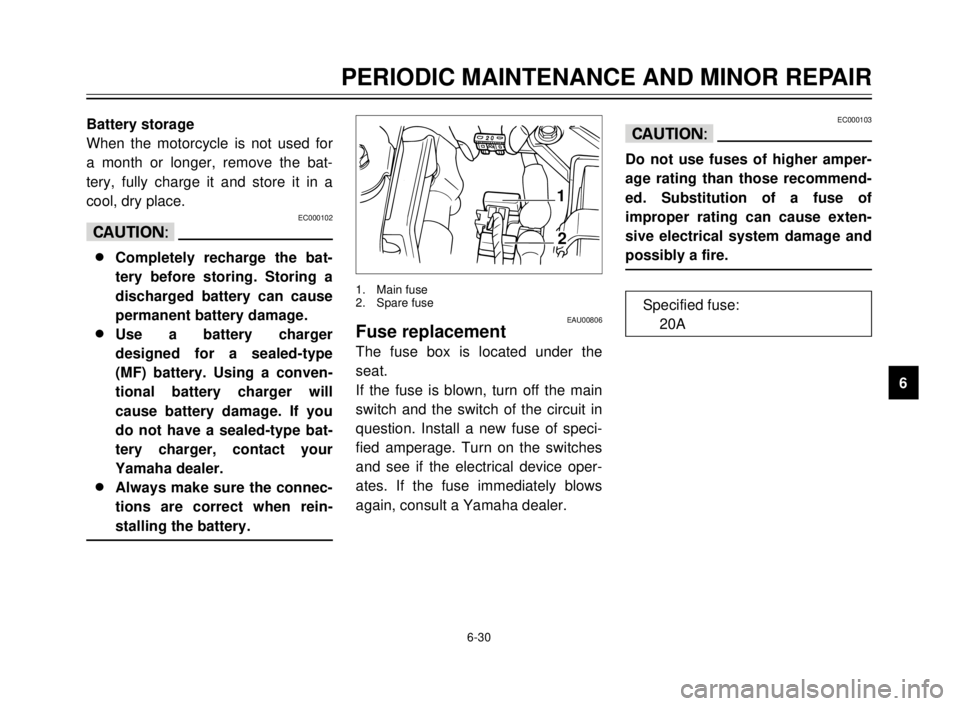
EAU00806Fuse replacement
The fuse box is located under the
seat.
If the fuse is blown, turn off the main
switch and the switch of the circuit in
question. Install a new fuse of speci-
fied amperage. Turn on the switches
and see if the electrical device oper-
ates. If the fuse immediately blows
again, consult a Yamaha dealer.
1. Main fuse
2. Spare fuse
EC000103
cC
Do not use fuses of higher amper-
age rating than those recommend-
ed. Substitution of a fuse of
improper rating can cause exten-
sive electrical system damage and
possibly a fire.
Specified fuse:
20A
5AE-9-E3 (ENG) 4/11/0 11:06 AM Page 73
Page 77 of 104
6-32
PERIODIC MAINTENANCE AND MINOR REPAIR
1
2
3
4
5
6
7
8
9
12
EAU01078
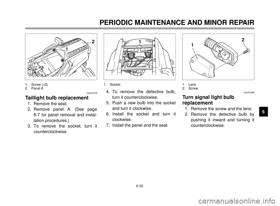
Taillight bulb replacement
1. Remove the seat.
2. Remove panel A. (See page
6-7 for panel removal and instal-
lation procedures.)
3. To remove the socket, turn it
counterclockwise.
1. Screw (´2)
2. Panel A
1
4. To remove the defective bulb,
turn it counterclockwise.
5. Push a new bulb into the socket
and turn it clockwise.
6. Install the socket and turn it
clockwise.
7. Install the panel and the seat.
1. Socket
12
EAU01095
Turn signal light bulb
replacement
1. Remove the screw and the lens.
2. Remove the defective bulb by
pushing it inward and turning it
counterclockwise.
1. Lens
2. Screw
5AE-9-E3 (ENG) 4/11/0 11:06 AM Page 75