suspension YAMAHA TDR 125 2000 Owners Manual
[x] Cancel search | Manufacturer: YAMAHA, Model Year: 2000, Model line: TDR 125, Model: YAMAHA TDR 125 2000Pages: 104, PDF Size: 4.88 MB
Page 45 of 104
PERIODIC MAINTENANCE AND MINOR REPAIR
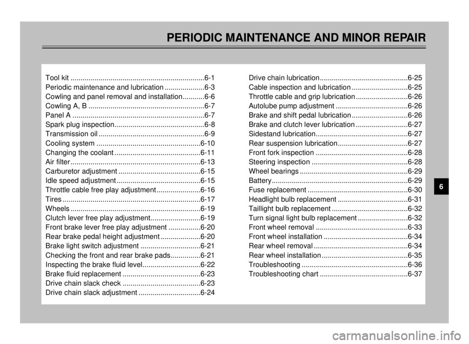
Tool kit ...................................................................6-1
Periodic maintenance and lubrication ....................6-3
Cowling and panel removal and installation...........6-6
Cowling A, B ..........................................................6-7
Panel A ..................................................................6-7
Spark plug inspection.............................................6-8
Transmission oil .....................................................6-9
Cooling system ....................................................6-10
Changing the coolant ...........................................6-11
Air filter .................................................................6-13
Carburetor adjustment .........................................6-15
Idle speed adjustment ..........................................6-15
Throttle cable free play adjustment ......................6-16
Tires .....................................................................6-17
Wheels .................................................................6-19
Clutch lever free play adjustment.........................6-19
Front brake lever free play adjustment ................6-20
Rear brake pedal height adjustment ....................6-20
Brake light switch adjustment ..............................6-21
Checking the front and rear brake pads...............6-21
Inspecting the brake fluid level.............................6-22
Brake fluid replacement .......................................6-23
Drive chain slack check .......................................6-23
Drive chain slack adjustment ...............................6-24Drive chain lubrication............................................6-25
Cable inspection and lubrication ............................6-25
Throttle cable and grip lubrication ..........................6-26
Autolube pump adjustment ....................................6-26
Brake and shift pedal lubrication ............................6-26
Brake and clutch lever lubrication ..........................6-27
Sidestand lubrication..............................................6-27
Rear suspension lubrication...................................6-27
Front fork inspection ..............................................6-28
Steering inspection ................................................6-28
Wheel bearings ......................................................6-29
Battery....................................................................6-29
Fuse replacement ..................................................6-30
Headlight bulb replacement ...................................6-31
Taillight bulb replacement ......................................6-32
Turn signal light bulb replacement .........................6-32
Front wheel removal ..............................................6-33
Front wheel installation ..........................................6-34
Rear wheel removal ...............................................6-34
Rear wheel installation ...........................................6-35
Troubleshooting .....................................................6-36
Troubleshooting chart ............................................6-37
6
5AE-9-E3 (ENG) 4/11/0 11:06 AM Page 43
Page 62 of 104
6-17
PERIODIC MAINTENANCE AND MINOR REPAIR
1
2
3
4
5
6
7
8
9
EAU00647Tires
To ensure maximum performance,
long service, and safe operation, note
the following:
Tire air pressure
Always check and adjust the tire
pressure before operating the motor-
cycle.
EW000082
w
Tire inflation pressure should be
checked and adjusted when the
temperature of the tire equals the
ambient air temperature. Tire infla-
tion pressure must be adjusted
according to total weight of cargo,
rider, passenger, and accessories
(fairing, saddlebags, etc. if
approved for this model), and vehi-
cle speed.
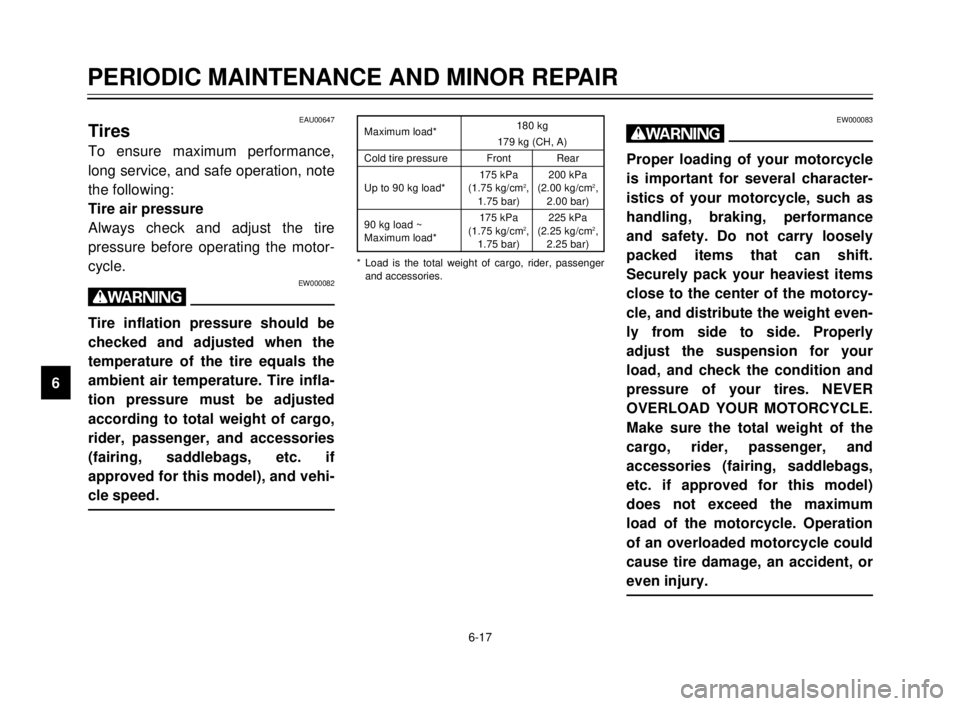
* Load is the total weight of cargo, rider, passenger
and accessories. Maximum load*180 kg
179 kg (CH, A)
Cold tire pressure Front Rear
175 kPa 200 kPa
Up to 90 kg load* (1.75 kg/cm
2, (2.00 kg/cm2,1.75 bar) 2.00 bar)
90 kg load ~175 kPa 225 kPa
Maximum load*(1.75 kg/cm
2, (2.25 kg/cm2,
1.75 bar) 2.25 bar)
EW000083
w
Proper loading of your motorcycle
is important for several character-
istics of your motorcycle, such as
handling, braking, performance
and safety. Do not carry loosely
packed items that can shift.
Securely pack your heaviest items
close to the center of the motorcy-
cle, and distribute the weight even-
ly from side to side. Properly
adjust the suspension for your
load, and check the condition and
pressure of your tires. NEVER
OVERLOAD YOUR MOTORCYCLE.
Make sure the total weight of the
cargo, rider, passenger, and
accessories (fairing, saddlebags,
etc. if approved for this model)
does not exceed the maximum
load of the motorcycle. Operation
of an overloaded motorcycle could
cause tire damage, an accident, or
even injury.
5AE-9-E3 (ENG) 4/11/0 11:06 AM Page 60
Page 72 of 104
6-27
PERIODIC MAINTENANCE AND MINOR REPAIR
1
2
3
4
5
6
7
8
9
EAU02986
Sidestand lubrication
Lubricate the sidestand pivoting point
and metal-to-metal contact surfaces.
Check that the sidestand moves up
and down smoothly.
EW000113
w
If the sidestand does not move
smoothly, consult a Yamaha deal-
er.
Recommended lubricant:
Engine oil
EAU00791
Rear suspension lubrication
Lubricate the pivoting parts.
Recommended lubricant:
Lithium soap base grease
EAU02939
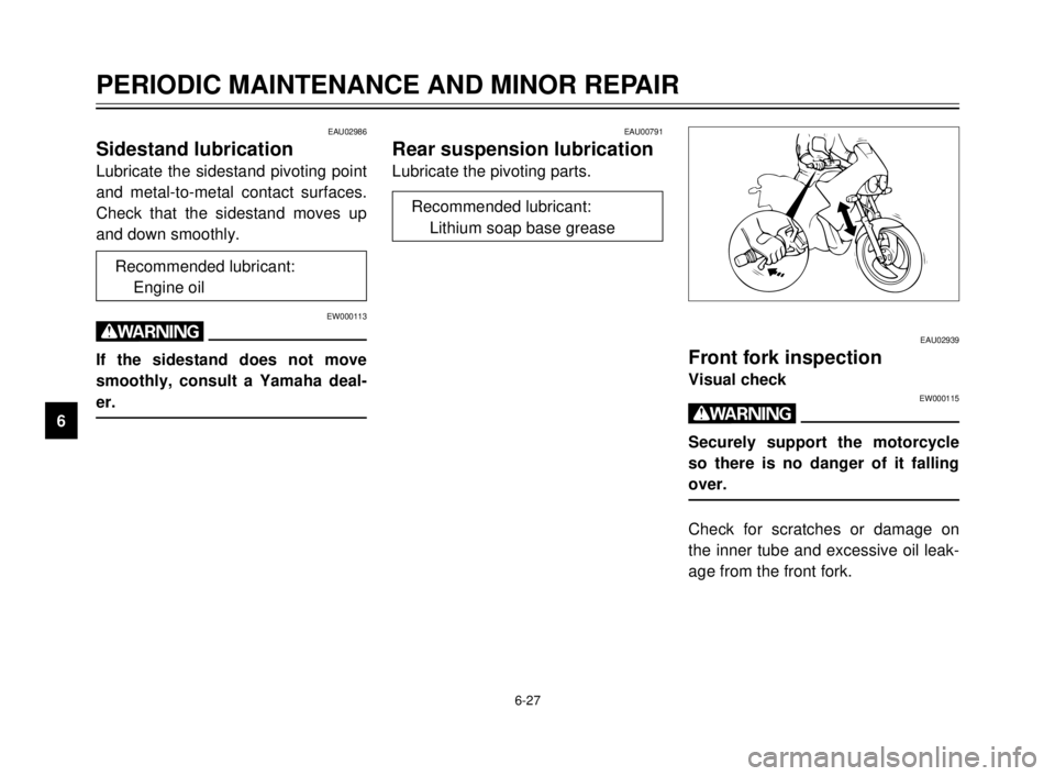
Front fork inspection
Visual checkEW000115
w
Securely support the motorcycle
so there is no danger of it falling
over.
Check for scratches or damage on
the inner tube and excessive oil leak-
age from the front fork.
5AE-9-E3 (ENG) 4/11/0 11:06 AM Page 70
Page 94 of 104
SPECIFICATIONS
1
2
3
4
5
6
7
8
9
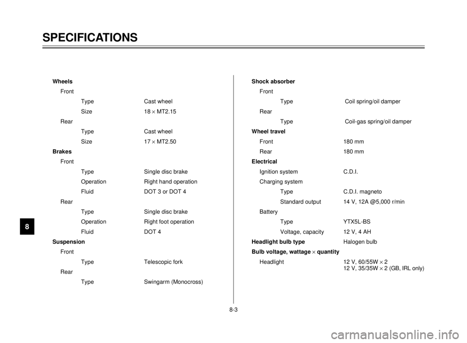
Wheels
Front
Type Cast wheel
Size 18 ´MT2.15
Rear
Type Cast wheel
Size 17 ´MT2.50
Brakes
Front
Type Single disc brake
Operation Right hand operation
Fluid DOT 3 or DOT 4
Rear
Type Single disc brake
Operation Right foot operation
Fluid DOT 4
Suspension
Front
Type Telescopic fork
Rear
Type Swingarm (Monocross)Shock absorber
Front
Type Coil spring/oil damper
Rear
Type Coil-gas spring/oil damper
Wheel travel
Front 180 mm
Rear 180 mm
Electrical
Ignition system C.D.I.
Charging system
Type C.D.I. magneto
Standard output 14 V, 12A @5,000 r/min
Battery
Type YTX5L-BS
Voltage, capacity 12 V, 4 AH
Headlight bulb typeHalogen bulb
Bulb voltage, wattage ´quantity
Headlight 12 V, 60/55W ´2
12 V, 35/35W ´2 (GB, IRL only)
8-3
5AE-9-E3 (ENG) 4/11/0 11:06 AM Page 92
Page 100 of 104
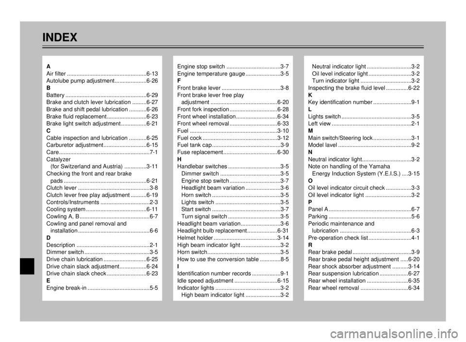
INDEX
Engine stop switch ..................................3-7
Engine temperature gauge ......................3-5
F
Front brake lever .....................................3-8
Front brake lever free play
adjustment ..........................................6-20
Front fork inspection ..............................6-28
Front wheel installation..........................6-34
Front wheel removal ..............................6-33
Fuel .......................................................3-10
Fuel cock ...............................................3-12
Fuel tank cap ...........................................3-9
Fuse replacement..................................6-30
H
Handlebar switches .................................3-5
Dimmer switch ......................................3-5
Engine stop switch ................................3-7
Headlight beam variation ......................3-6
Horn switch ...........................................3-5
Lights switch .........................................3-5
Start switch ...........................................3-7
Turn signal switch .................................3-5
Headlight beam variation.........................3-6
Headlight bulb replacement...................6-31
Helmet holder ........................................3-14
High beam indicator light .........................3-2
Horn switch..............................................3-5
How to use the conversion table .............8-5
I
Identification number records ..................9-1
Idle speed adjustment ...........................6-15
Indicator lights .........................................3-2
High beam indicator light ......................3-2Neutral indicator light ............................3-2
Oil level indicator light ...........................3-2
Turn indicator light ................................3-2
Inspecting the brake fluid level ..............6-22
K
Key identification number ........................9-1
L
Lights switch ............................................3-5
Left view ..................................................2-1
M
Main switch/Steering lock ........................3-1
Model lavel ..............................................9-2
N
Neutral indicator light...............................3-2
Note on handling of the Yamaha
Energy Induction System (Y.E.I.S.) ....3-15
O
Oil level indicator circuit check ................3-3
Oil level indicator light .............................3-2
P
Panel A ....................................................6-7
Parking ....................................................5-6
Periodic maintenance and
lubrication .............................................6-3
Pre-operation check list ...........................4-1
R
Rear brake pedal .....................................3-9
Rear brake pedal height adjustment .....6-20
Rear shock absorber adjustment ..........3-14
Rear suspension lubrication ..................6-27
Rear wheel installation ..........................6-35
Rear wheel removal ..............................6-34A
Air filter ..................................................6-13
Autolube pump adjustment....................6-26
B
Battery ...................................................6-29
Brake and clutch lever lubrication .........6-27
Brake and shift pedal lubrication ...........6-26
Brake fluid replacement.........................6-23
Brake light switch adjustment ................6-21
C
Cable inspection and lubrication ...........6-25
Carburetor adjustment...........................6-15
Care.........................................................7-1
Catalyzer
(for Switzerland and Austria) ..............3-11
Checking the front and rear brake
pads ....................................................6-21
Clutch lever .............................................3-8
Clutch lever free play adjustment ..........6-19
Controls/Instruments ...............................2-3
Cooling system ......................................6-11
Cowling A, B ............................................6-7
Cowling and panel removal and
installation .............................................6-6
D
Description ..............................................2-1
Dimmer switch .........................................3-5
Drive chain lubrication ...........................6-25
Drive chain slack adjustment.................6-24
Drive chain slack check .........................6-23
E
Engine break-in .......................................5-5
5AE-9-E3 (ENG) 4/11/0 11:06 AM Page 98