suspension YAMAHA TDR 125 2002 Owners Manual
[x] Cancel search | Manufacturer: YAMAHA, Model Year: 2002, Model line: TDR 125, Model: YAMAHA TDR 125 2002Pages: 94, PDF Size: 2.43 MB
Page 7 of 94

Checking the spark plug ................................ 6-7
Transmission oil ............................................. 6-8
Coolant ......................................................... 6-10
Cleaning the air filter element ..................... 6-13
Adjusting the carburetor ............................... 6-15
Adjusting the engine idling speed ................ 6-16
Adjusting the throttle cable free play ............ 6-17
Tires ............................................................. 6-17
Cast wheels ................................................. 6-19
Adjusting the clutch lever free play .............. 6-20
Adjusting the brake lever free play ............... 6-21
Adjusting the brake pedal position ............... 6-22
Adjusting the rear brake light switch ............ 6-22
Checking the front and rear brake pads ....... 6-23
Checking the brake fluid level ...................... 6-24
Changing the brake fluid .............................. 6-25
Drive chain slack .......................................... 6-25
Lubricating the drive chain ........................... 6-26
Checking and lubricating the cables ............ 6-27
Checking and lubricating the throttle grip
and cable ................................................... 6-28
Adjusting the Autolube pump ....................... 6-28
Checking and lubricating the brake and
shift pedals ................................................. 6-29
Checking and lubricating the brake and
clutch levers .................................................6-29
Checking and lubricating the sidestand ....... 6-29Lubricating the rear suspension ................... 6-30
Checking the front fork ................................. 6-30
Checking the steering .................................. 6-31
Checking the wheel bearings ....................... 6-32
Battery .......................................................... 6-32
Replacing the fuse ....................................... 6-33
Replacing a headlight bulb ........................... 6-34
Replacing the tail/brake light bulb ................ 6-35
Replacing a turn signal light bulb ................. 6-36
Supporting the motorcycle ........................... 6-37
Front wheel .................................................. 6-37
Rear wheel ................................................... 6-39
Troubleshooting ........................................... 6-41
Troubleshooting charts ................................ 6-42
MOTORCYCLE CARE AND STORAGE ........... 7-1
Care ............................................................... 7-1
Storage .......................................................... 7-4
SPECIFICATIONS ............................................ 8-1
Conversion table ............................................ 8-5
CONSUMER INFORMATION .............................9-1
Identification numbers .................................... 9-1
Key identification number ............................... 9-1
Vehicle identification number ......................... 9-1
Model label ..................................................... 9-2
TABLE OF CONTENTS
789
5AE-28199-E5 honbun 7/6/01 10:18 AM Page 6
Page 24 of 94

3-13
INSTRUMENT AND CONTROL FUNCTIONS
3
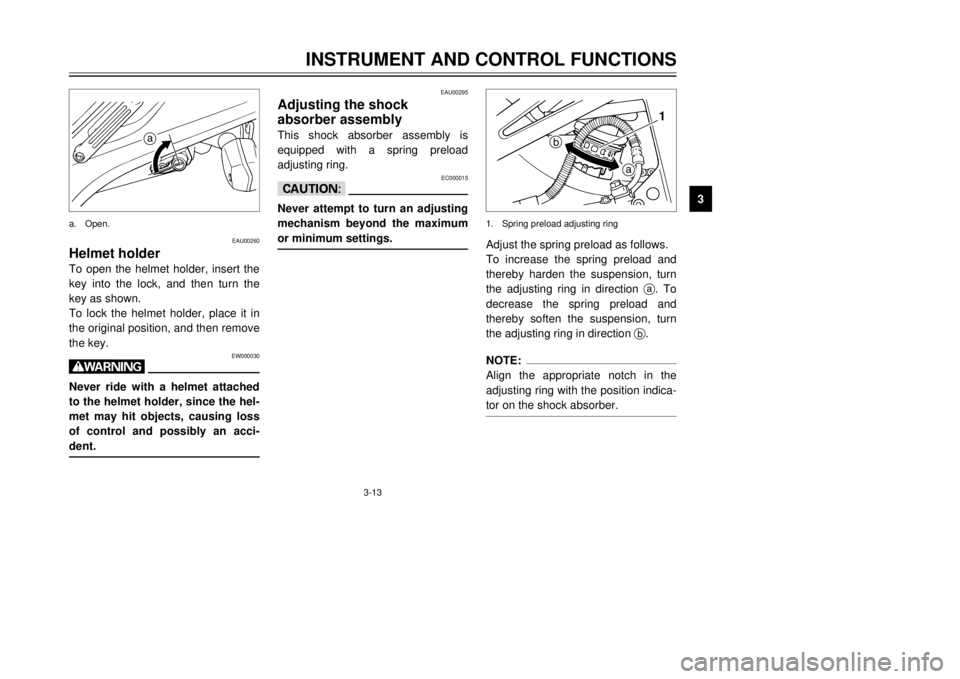
EAU00260
Helmet holderTo open the helmet holder, insert the
key into the lock, and then turn the
key as shown.
To lock the helmet holder, place it in
the original position, and then remove
the key.
EW000030
wNever ride with a helmet attached
to the helmet holder, since the hel-
met may hit objects, causing loss
of control and possibly an acci-
dent.
EAU00295
Adjusting the shock
absorber assemblyThis shock absorber assembly is
equipped with a spring preload
adjusting ring.
EC000015
cCNever attempt to turn an adjusting
mechanism beyond the maximum
or minimum settings.
Adjust the spring preload as follows.
To increase the spring preload and
thereby harden the suspension, turn
the adjusting ring in direction a. To
decrease the spring preload and
thereby soften the suspension, turn
the adjusting ring in direction b.NOTE:
Align the appropriate notch in the
adjusting ring with the position indica-
tor on the shock absorber.
a
a
b1
a. Open.1. Spring preload adjusting ring
5AE-28199-E5 honbun 7/6/01 10:18 AM Page 23
Page 54 of 94

6-18
PERIODIC MAINTENANCE AND MINOR REPAIR
6
EWA00012
wBecause loading has an enormous
impact on the handling, braking,
performance and safety character-
istics of your motorcycle, you
should keep the following precau-
tions in mind.
8NEVER OVERLOAD THE
MOTORCYCLE! Operation of
an overloaded motorcycle may
result in tire damage, loss of
control, or severe injury. Make
sure that the total weight of
rider, passenger, cargo, and
accessories does not exceed
the specified maximum load
for the vehicle.
8Do not carry along loosely
packed items, which can shift
during a ride.
8Securely pack the heaviest
items close to the center of the
motorcycle and distribute the
weight evenly on both sides.
8Adjust the suspension and tire
air pressure with regard to the
load.
8Check the tire condition and
air pressure before each ride.
Tire inspection
The tires must be checked before
each ride. If the center tread depth
reaches the specified limit, if the tire
has a nail or glass fragments in it, or
if the sidewall is cracked, have a
Yamaha dealer replace the tire imme-
diately.NOTE:
The tire tread depth limits may differ
from country to country. Always com-
ply with the local regulations.
1a
1. Tire side wall
a. Tread depth
Tire air pressure
(measured on cold tires)
Load* Front Rear
Up to 90 kg175 kPa
(1.75 kgf/cm
2,
1.75 bar)200 kPa
(2.00 kgf/cm
2,
2.00 bar)
90 kg–maximum175 kPa
(1.75 kgf/cm
2,
1.75 bar)225 kPa
(2.25 kgf/cm
2,
2.25 bar)
Maximum load*180 kg
179 kg (CH, A)
* Total weight of rider, passenger, cargo and
accessories
Minimum tire tread depth
(front and rear)1.6 mm
5AE-28199-E5 honbun 7/6/01 10:18 AM Page 53
Page 66 of 94

6-30
PERIODIC MAINTENANCE AND MINOR REPAIR
6
EAU03166
Lubricating the rear
suspensionRear suspension, lubricatingThe pivoting points of the rear sus-
pension must be lubricated at the
intervals specified in the periodic
maintenance and lubrication chart.
EAU02939
Checking the front forkThe condition and operation of the
front fork must be checked as follows
at the intervals specified in the peri-
odic maintenance and lubrication
chart.
To check the condition
EW000115
wSecurely support the motorcycle
so that there is no danger of it
falling over.Check the inner tubes for scratches,
damage and excessive oil leakage. Recommended lubricant:
Lithium-soap-based grease
(all-purpose grease)
Recommended lubricant:
Lithium-soap-based grease
(all-purpose grease)
5AE-28199-E5 honbun 7/6/01 10:18 AM Page 65
Page 87 of 94

8-3
SPECIFICATIONS
8
Wheels
Front
Type Cast
Size 18 ×MT2.15 or
18 M/C ×MT2.15
Rear
Type Cast
Size 17 ×MT2.50 or
17 M/C ×MT2.50
Brakes
Front
Type Single disc brake
Operation Right hand
Fluid DOT 4
Rear
Type Single disc brake
Operation Right foot
Fluid DOT 4Suspension
Front
Type Telescopic fork
Rear
Type Swingarm (Monocross)
Spring/shock absorber
Front
Type Coil spring/oil damper
Rear
Type Coil-gas spring/oil damper
Wheel travel
Front 180 mm
Rear 180 mm
Electrical
Ignition system C.D.I.
Charging system
Type A.C. magneto
Standard output 14 V, 12A @ 5,000 r/min
Battery
Type YTX5L-BS
Voltage, capacity 12 V, 4 Ah
5AE-28199-E5 honbun 7/6/01 10:18 AM Page 86