drain bolt YAMAHA TENERE 700 2020 Owners Manual
[x] Cancel search | Manufacturer: YAMAHA, Model Year: 2020, Model line: TENERE 700, Model: YAMAHA TENERE 700 2020Pages: 102, PDF Size: 10.31 MB
Page 13 of 102

Description
2-1
2
EAU10411
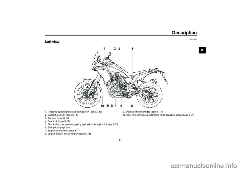
Left view
1
2
3
4
6
5 10
7
9
8
1. Rebound damping force adjusting screw (page 3-23)
2. Coolant reservoir (page 6-14)
3. Canister (page 6-10)
4. Seat lock (page 3-19)
5. Shock absorber assembly spring preload adjusting knob (page 3-23)
6. Shift pedal (page 3-14)
7. Engine oil drain bolt (page 6-11)
8. Engine oil level check window (page 6-11)9. Engine oil filter cartridge (page 6-11)
10.Front fork compression damping force adjusting screw (page 3-21)
UBW3E0E0.book Page 1 Friday, May 24, 2019 11:01 AM
Page 41 of 102

Instrument and control functions
3-26
3
EAUM4130
Front fender To suit the riding conditions, the front
fender height can be adjusted.
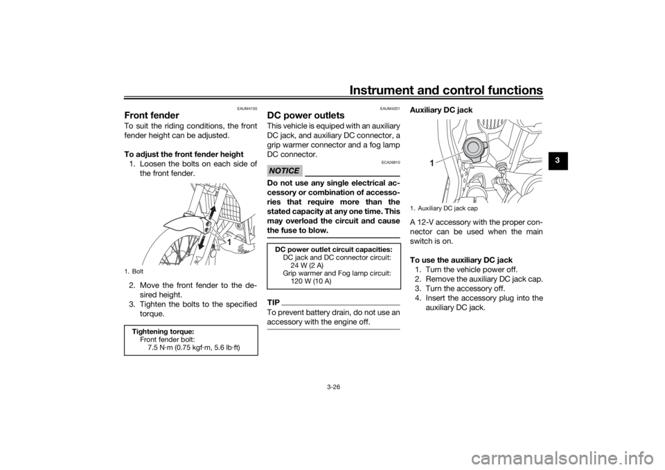
To adjust the front fender height
1. Loosen the bolts on each side of
the front fender.
2. Move the front fender to the de-
sired height.
3. Tighten the bolts to the specified
torque.
EAUM4201
DC power outletsThis vehicle is equiped with an auxiliary
DC jack, and auxiliary DC connector, a
grip warmer connector and a fog lamp
DC connector.NOTICE
ECA26810
Do not use any single electrical ac-
cessory or combination of accesso-
ries that require more than the
stated capacity at any one time. This
may overload the circuit and cause
the fuse to blow.TIPTo prevent battery drain, do not use an
accessory with the engine off.
Auxiliary DC jack
A 12-V accessory with the proper con-
nector can be used when the main
switch is on.
To use the auxiliary DC jack
1. Turn the vehicle power off.
2. Remove the auxiliary DC jack cap.
3. Turn the accessory off.
4. Insert the accessory plug into the
auxiliary DC jack.
1. BoltTightening torque:
Front fender bolt:
7.5 N·m (0.75 kgf·m, 5.6 lb·ft)
1
DC power outlet circuit capacities:
DC jack and DC connector circuit:
24 W (2 A)
Grip warmer and Fog lamp circuit:
120 W (10 A)
1. Auxiliary DC jack cap
1
UBW3E0E0.book Page 26 Friday, May 24, 2019 11:01 AM
Page 62 of 102

Periodic maintenance and adjustment
6-11
6
EAUM4151
Engine oil and oil filter car-
tridgeThe engine oil level should be checked
before each ride. In addition, the oil
must be changed and the oil filter car-
tridge replaced at the intervals speci-
fied in the periodic maintenance chart.
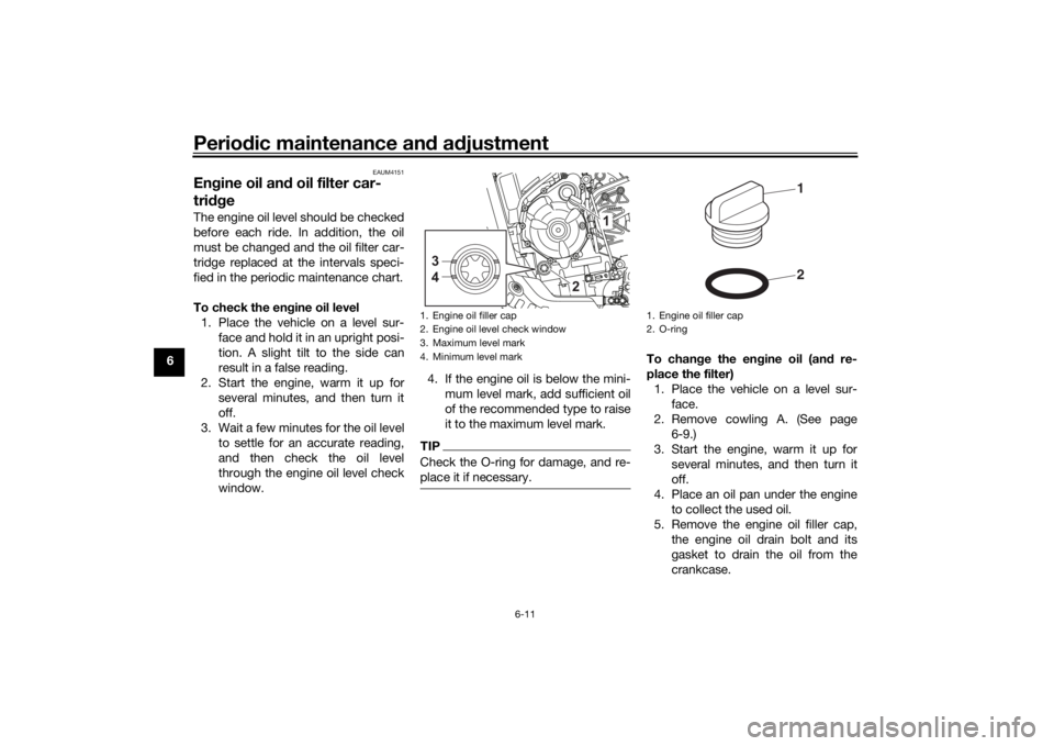
To check the engine oil level
1. Place the vehicle on a level sur-
face and hold it in an upright posi-
tion. A slight tilt to the side can
result in a false reading.
2. Start the engine, warm it up for
several minutes, and then turn it
off.
3. Wait a few minutes for the oil level
to settle for an accurate reading,
and then check the oil level
through the engine oil level check
window.4. If the engine oil is below the mini-
mum level mark, add sufficient oil
of the recommended type to raise
it to the maximum level mark.
TIPCheck the O-ring for damage, and re-
place it if necessary.
To change the engine oil (and re-
place the filter)
1. Place the vehicle on a level sur-
face.
2. Remove cowling A. (See page
6-9.)
3. Start the engine, warm it up for
several minutes, and then turn it
off.
4. Place an oil pan under the engine
to collect the used oil.
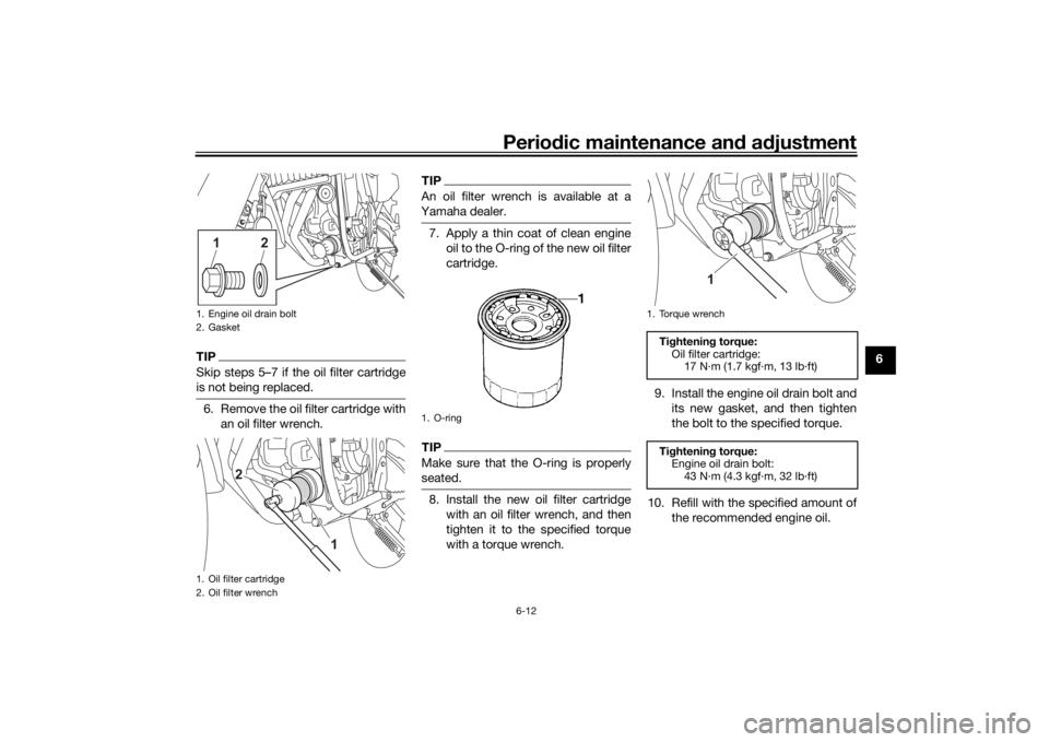
5. Remove the engine oil filler cap,
the engine oil drain bolt and its
gasket to drain the oil from the
crankcase.
1. Engine oil filler cap
2. Engine oil level check window
3. Maximum level mark
4. Minimum level mark3
4
2
1
1. Engine oil filler cap
2. O-ring
21
UBW3E0E0.book Page 11 Friday, May 24, 2019 11:01 AM
Page 63 of 102

Periodic maintenance and adjustment
6-12
6
TIPSkip steps 5–7 if the oil filter cartridge
is not being replaced.6. Remove the oil filter cartridge with
an oil filter wrench.
TIPAn oil filter wrench is available at a
Yamaha dealer.7. Apply a thin coat of clean engine
oil to the O-ring of the new oil filter
cartridge.TIPMake sure that the O-ring is properly
seated.8. Install the new oil filter cartridge
with an oil filter wrench, and then
tighten it to the specified torque
with a torque wrench.9. Install the engine oil drain bolt and
its new gasket, and then tighten
the bolt to the specified torque.
10. Refill with the specified amount of
the recommended engine oil.
1. Engine oil drain bolt
2. Gasket
1. Oil filter cartridge
2. Oil filter wrench
12
1
2
1. O-ring
1. Torque wrench
Tightening torque:
Oil filter cartridge:
17 N·m (1.7 kgf·m, 13 lb·ft)
Tightening torque:
Engine oil drain bolt:
43 N·m (4.3 kgf·m, 32 lb·ft)
1
UBW3E0E0.book Page 12 Friday, May 24, 2019 11:01 AM
Page 92 of 102

Motorcycle care and storage
7-4
71. Make all necessary repairs and
perform any outstanding mainte-
nance.
2. Follow all instructions in the Care
section of this chapter.
3. Fill up the fuel tank, adding fuel
stabilizer according to product in-
structions. Run the engine for 5
minutes to distribute treated fuel
through the fuel system.
4. For vehicles equipped with a fuel
cock: Turn the fuel cock lever to
the off position.
5. For vehicles with a carburetor: To
prevent fuel deposits from build-
ing up, drain the fuel in the carbu-
retor float chamber into a clean
container. Retighten the drain bolt
and pour the fuel back into the fuel
tank.
6. Use a quality engine fogging oil
according to product instructions
to protect internal engine compo-
nents from corrosion. If engine
fogging oil is not available, per-
form the following steps for each
cylinder:
a. Remove the spark plug cap
and spark plug.b. Pour a teaspoonful of engine
oil into the spark plug bore.
c. Install the spark plug cap onto
the spark plug, and then place
the spark plug on the cylinder
head so that the electrodes are
grounded. (This will limit spark-
ing during the next step.)
d. Turn the engine over several
times with the starter. (This will
coat the cylinder wall with oil.)
WARNING! To prevent dam-
age or injury from sparking,
make sure to ground the
spark plug electrodes while
turning the engine over.
[EWA10952]
e. Remove the spark plug cap
from the spark plug, and then
install the spark plug and the
spark plug cap.
7. Lubricate all control cables, piv-
ots, levers and pedals, as well as
the sidestand and centerstand (if
equipped).
8. Check and correct the tire air
pressure, and then lift the vehicle
so that all wheels are off the
ground. Otherwise, turn thewheels a little once a month in or-
der to prevent the tires from be-
coming degraded in one spot.
9. Cover the muffler outlet with a
plastic bag to prevent moisture
from entering it.
10. Remove the battery and fully
charge it, or attach a maintenance
charger to keep the battery opti-
mally charged. NOTICE: Confirm
that the battery and its charger
are compatible. Do not charge a
VRLA battery with a convention-
al charger.
[ECA26330]
TIPIf the battery will be removed,
charge it once a month and store
it in a temperate location between
0-30 °C (32-90 °F).
See page 6-30 for more informa-
tion on charging and storing the
battery.
UBW3E0E0.book Page 4 Friday, May 24, 2019 11:01 AM