warning YAMAHA TENERE 700 RALLY EDITION 2021 User Guide
[x] Cancel search | Manufacturer: YAMAHA, Model Year: 2021, Model line: TENERE 700 RALLY EDITION, Model: YAMAHA TENERE 700 RALLY EDITION 2021Pages: 102, PDF Size: 6.31 MB
Page 31 of 102
Instrument and control functions
3-16
3
EAU12944
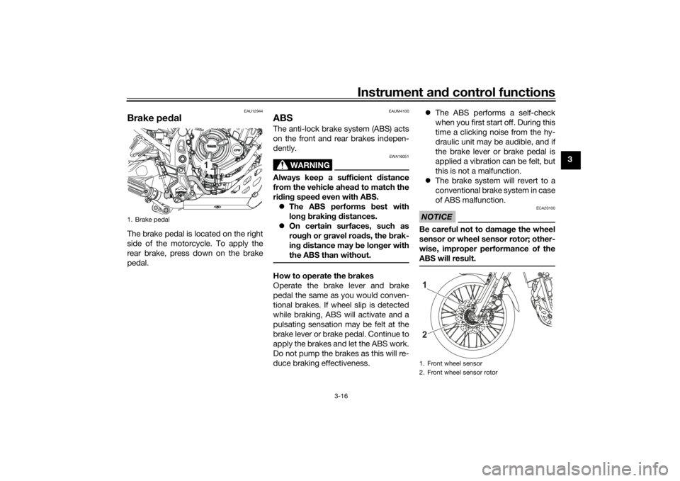
Brake ped alThe brake pedal is located on the right
side of the motorcycle. To apply the
rear brake, press down on the brake
pedal.
EAUM4100
ABSThe anti-lock brake system (ABS) acts
on the front and rear brakes indepen-
dently.
WARNING
EWA16051
Always keep a sufficient d istance
from the vehicle ahea d to match the
ri din g speed even with ABS.
The ABS performs best with
lon g b rakin g d istances.
On certain surfaces, such as
rou gh or g ravel roa ds, the b rak-
in g d istance may be lon ger with
the ABS than without.How to operate the brakes
Operate the brake lever and brake
pedal the same as you would conven-
tional brakes. If wheel slip is detected
while braking, ABS will activate and a
pulsating sensation may be felt at the
brake lever or brake pedal. Continue to
apply the brakes and let the ABS work.
Do not pump the brakes as this will re-
duce braking effectiveness.
The ABS performs a self-check
when you first start off. During this
time a clicking noise from the hy-
draulic unit may be audible, and if
the brake lever or brake pedal is
applied a vibration can be felt, but
this is not a malfunction.
The brake system will revert to a
conventional brake system in case
of ABS malfunction.
NOTICE
ECA20100
Be careful not to d amage the wheel
sensor or wheel sensor rotor; other-
wise, improper performance of the
ABS will result.
1. Brake pedal
1
1. Front wheel sensor
2. Front wheel sensor rotor21
UBEHEAE0.book Page 16 Thursday, January 21, 2021 5:45 PM
Page 32 of 102

Instrument and control functions
3-17
3
TIPWhen riding off-road, the ABS can be
disabled. (See page 3-9.)
WARNING
EWAM1050
Always ri de on paved roads with the
ABS turne d on. Ri din g on pu blic
roa ds with the ABS disa ble d may b e
ille gal an d voi d your insurance. Turn
the ABS off only when ri din g on non-
pave d surfaces.
EAUM1795
Fuel tank capTo remove the fuel tank cap
1. Open the fuel tank cap lock cover.
2. Insert the key and turn it 1/4 turn clockwise. The lock will be re-
leased and the fuel tank cap can
be removed.
To install the fuel tank cap 1. Push and install the fuel tank cap into position with the key inserted.
2. Turn the key counterclockwise to the original position, and then re-
move it.
TIPThe fuel tank cap cannot be installed
unless the key is in the lock. In addi-
tion, the key cannot be removed if the
cap is not properly installed and
locked.3. Close the lock cover.
WARNING
EWA11142
Make sure that the fuel tank cap is
properly installe d before ri din g.
Leakin g fuel is a fire hazar d.
1. Rear wheel sensor
2. Rear wheel sensor rotor12
1. Fuel tank cap lock cover
2. Unlock.
1
2
UBEHEAE0.book Page 17 Thursday, January 21, 2021 5:45 PM
Page 33 of 102
Instrument and control functions
3-18
3
EAU13222
FuelMake sure there is sufficient gasoline in
the tank.
WARNING
EWA10882
Gasoline an d gasoline vapors are
extremely flammab le. To avoid fires
an d explosions an d to re duce the
risk of injury when refuelin g, follow
these instructions.1. Before refueling, turn off the en- gine and be sure that no one is sit-
ting on the vehicle. Never refuel
while smoking, or while in the vi-
cinity of sparks, open flames, or
other sources of ignition such as
the pilot lights of water heaters
and clothes dryers.
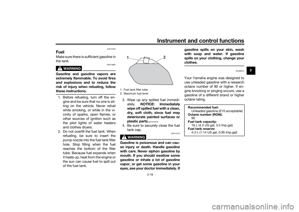
2. Do not overfill the fuel tank. When refueling, be sure to insert the
pump nozzle into the fuel tank filler
hole. Stop filling when the fuel
reaches the bottom of the filler
tube. Because fuel expands when
it heats up, heat from the engine or
the sun can cause fuel to spill out
of the fuel tank. 3. Wipe up any spilled fuel immedi-
ately. NOTICE: Immediately
wipe off spille d fuel with a clean,
d ry, soft cloth, since fuel may
d eteriorate painte d surfaces or
plastic parts.
[ECA10072]
4. Be sure to securely close the fuel tank cap.
WARNING
EWA15152
Gasoline is poisonous an d can cau-
se injury or death. Han dle gasoline
with care. Never siphon gasoline by
mouth. If you shoul d swallow some
g asoline or inhale a lot of gasoline
vapor, or get some g asoline in your
eyes, see your d octor immediately. If g
asoline spills on your skin, wash
with soap an d water. If g asoline
spills on your clothin g, chan ge your
clothes.
EAU86072
Your Yamaha engine was designed to
use unleaded gasoline with a research
octane number of 90 or higher. If en-
gine knocking or pinging occurs, use a
gasoline of a different brand or higher
octane rating.
1. Fuel tank filler tube
2. Maximum fuel level
2
1
Recommen ded fuel:
Unleaded gasoline (E10 acceptable)
Octane num ber (RON):
90
Fuel tank capacity: 16 L (4.2 US gal, 3.5 Imp.gal)
Fuel tank reserve:
4.3 L (1.14 US gal, 0.95 Imp.gal)
UBEHEAE0.book Page 18 Thursday, January 21, 2021 5:45 PM
Page 35 of 102
Instrument and control functions
3-20
3
EAU13435
Catalytic converterThe exhaust system contains catalytic
converter(s) to reduce harmful exhaust
emissions.
WARNING
EWA10863
The exhaust system is hot after op-
eration. To prevent a fire hazar d or
b urns:
Do not park the vehicle near
possi ble fire hazar ds such as
g rass or other materials that
easily burn.
Park the vehicle in a place
where pe destrians or chil dren
are not likely to touch the hot
exhaust system.
Make sure that the exhaust sys-
tem has coole d down before
d oin g any maintenance work.
Do not allow the en gine to i dle
more than a few minutes. Lon g
i d lin g can cause a buil d-up of
heat.
EAUM3740
SeatTo remove the seat
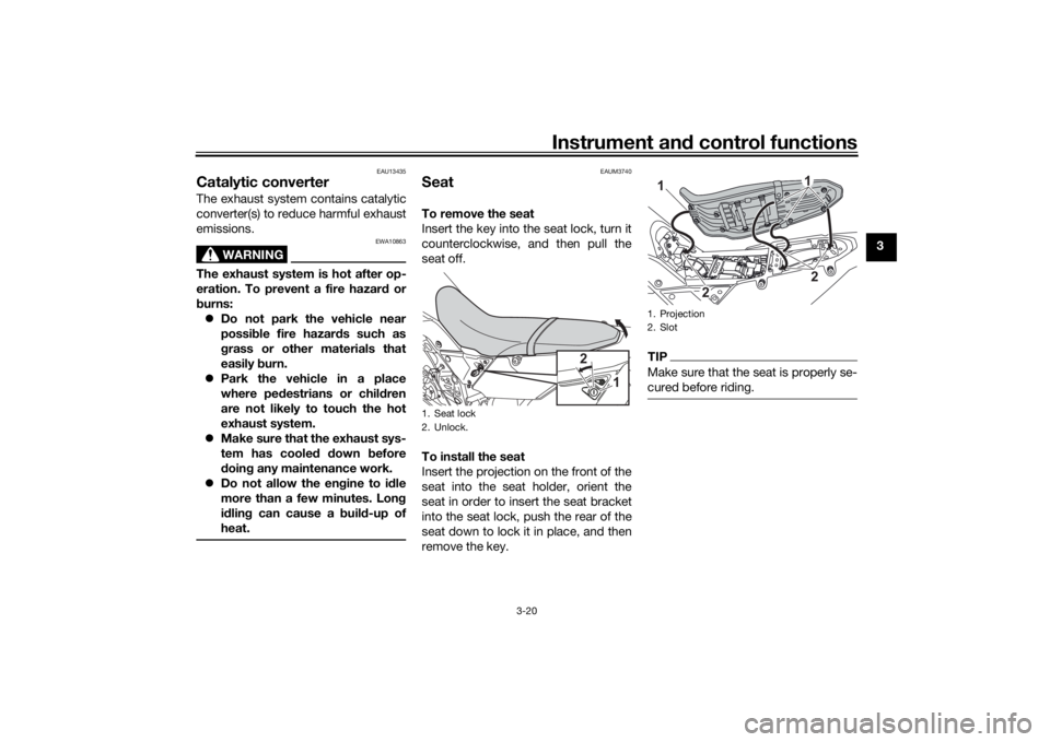
Insert the key into the seat lock, turn it
counterclockwise, and then pull the
seat off.
To install the seat
Insert the projection on the front of the
seat into the seat holder, orient the
seat in order to insert the seat bracket
into the seat lock, push the rear of the
seat down to lock it in place, and then
remove the key.
TIPMake sure that the seat is properly se-
cured before riding.
1. Seat lock
2. Unlock.
2
1
1. Projection
2. Slot
2
2
1 1
UBEHEAE0.book Page 20 Thursday, January 21, 2021 5:45 PM
Page 36 of 102
Instrument and control functions
3-21
3
EAU90940
A djustin g the hea dlig ht beamsThe headlight beam can be adjusted to
raise or lower the height of the head-
light beams. It may be necessary to ad-
just the headlight beams to increase
visibility and help prevent blinding on-
coming drivers when carrying more or
less load than usual. Obey local laws
and regulations concerning headlight
adjustment.
If headlights require adjustment, con-
sult a Yamaha dealer.
EAU45205
A djustin g the front fork
WARNING
EWA10181
Always a djust both fork le gs equally,
otherwise poor han dlin g an d loss of
sta bility may result.This front fork is equipped with re-
bound damping force adjusting screws
and compression damping force ad-
justing screws.NOTICE
ECA10102
To avoi d d amag ing the mechanism,
d o not attempt to turn b eyond the
maximum or minimum settin gs.Re boun d d ampin g force
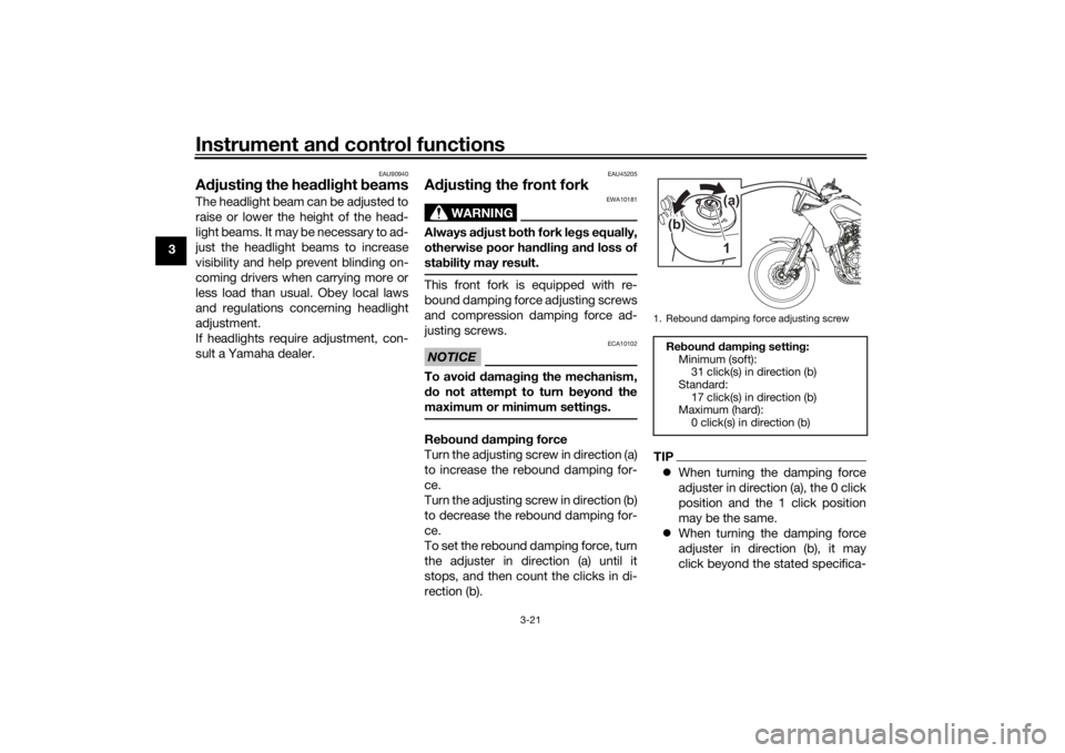
Turn the adjusting screw in direction (a)
to increase the rebound damping for-
ce.
Turn the adjusting screw in direction (b)
to decrease the rebound damping for-
ce.
To set the rebound damping force, turn
the adjuster in direction (a) until it
stops, and then count the clicks in di-
rection (b).
TIP When turning the damping force
adjuster in direction (a), the 0 click
position and the 1 click position
may be the same.
When turning the damping force
adjuster in direction (b), it may
click beyond the stated specifica-1. Rebound damping force adjusting screwReboun d d ampin g setting :
Minimum (soft): 31 click(s) in direction (b)
Standard: 17 click(s) in direction (b)
Maximum (hard):
0 click(s) in direction (b)
1
(b) (a)
UBEHEAE0.book Page 21 Thursday, January 21, 2021 5:45 PM
Page 38 of 102
Instrument and control functions
3-23
3
EAU14796
Front fork b leedin gWhen riding in extremely rough condi-
tions, the air temperature and pressure
in the front fork will rise and harden the
suspension. If this occurs, bleed the air
from each fork leg.
WARNING
EWA10201
Always blee d b oth fork le gs, other-
wise poor han dlin g an d loss of sta-
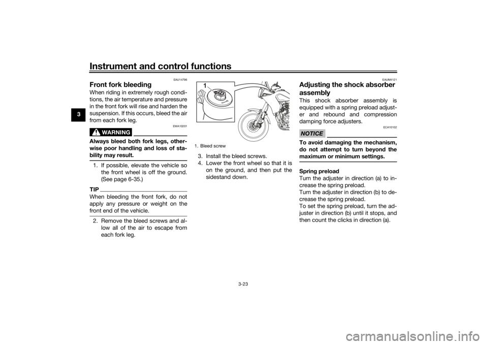
b ility may result.1. If possible, elevate the vehicle so
the front wheel is off the ground.
(See page 6-35.)TIPWhen bleeding the front fork, do not
apply any pressure or weight on the
front end of the vehicle.2. Remove the bleed screws and al-low all of the air to escape from
each fork leg. 3. Install the bleed screws.
4. Lower the front wheel so that it is
on the ground, and then put the
sidestand down.
EAUM4121
Adjustin g the shock a bsorb er
assem blyThis shock absorber assembly is
equipped with a spring preload adjust-
er and rebound and compression
damping force adjusters.NOTICE
ECA10102
To avoi d d amag ing the mechanism,
d o not attempt to turn b eyond the
maximum or minimum settin gs.Sprin g preloa d
Turn the adjuster in direction (a) to in-
crease the spring preload.
Turn the adjuster in direction (b) to de-
crease the spring preload.
To set the spring preload, turn the ad-
juster in direction (b) until it stops, and
then count the clicks in direction (a).
1. Bleed screw
1
UBEHEAE0.book Page 23 Thursday, January 21, 2021 5:45 PM
Page 40 of 102
Instrument and control functions
3-25
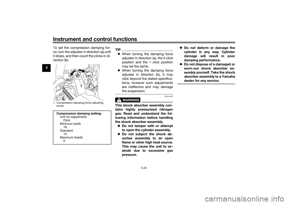
3 To set the compression damping for-
ce, turn the adjuster in direction (a) until
it stops, and then count the clicks in di-
rection (b).
TIP
When turning the damping force
adjuster in direction (a), the 0 click
position and the 1 click position
may be the same.
When turning the damping force
adjuster in direction (b), it may
click beyond the stated specifica-
tions, however such adjustments
are ineffective and may damage
the suspension.
WARNING
EWA10222
This shock a bsor ber assem bly con-
tains hi ghly pressurize d nitro gen
g as. Rea d an d un derstan d the fol-
lowin g information b efore handlin g
the shock a bsor ber assem bly.
Do not tamper with or attempt
to open the cylin der assem bly.
Do not su bject the shock a b-
sor ber assem bly to an open
flame or other hi gh heat source.
This may cause the unit to ex-
plo de due to excessive gas
pressure.
Do not deform or d amage the
cylin der in any way. Cylin der
d amag e will result in poor
d ampin g performance.
Do not d ispose of a damag ed or
worn-out shock a bsor ber as-
sem bl
y yourself. Take the shock
a b sor ber assem bly to a Yamaha
d ealer for any service.
1. Compression damping force adjusting
screwCompression dampin g settin g:
Unit for adjustment: Click
Minimum (soft): 18
Standard:
15
Maximum (hard): 0
1
(b) (a)
UBEHEAE0.book Page 25 Thursday, January 21, 2021 5:45 PM
Page 42 of 102
Instrument and control functions
3-27
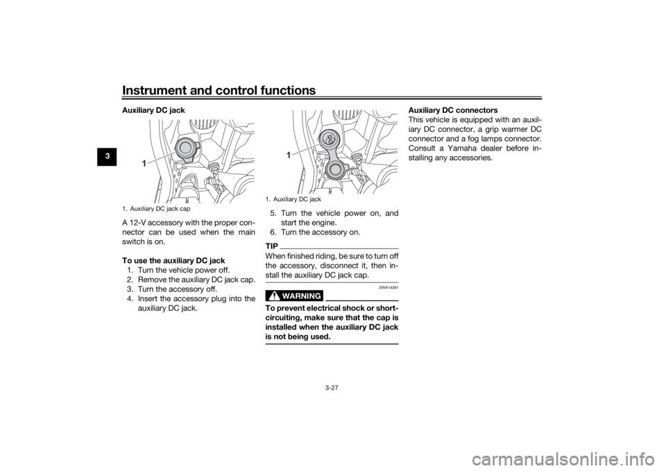
3 Auxiliary DC jack
A 12-V accessory with the proper con-
nector can be used when the main
switch is on.
To use the auxiliary DC jack
1. Turn the vehicle power off.
2. Remove the auxiliary DC jack cap.
3. Turn the accessory off.
4. Insert the accessory plug into the auxiliary DC jack. 5. Turn the vehicle power on, and
start the engine.
6. Turn the accessory on.
TIPWhen finished riding, be sure to turn off
the accessory, disconnect it, then in-
stall the auxiliary DC jack cap.
WARNING
EWA14361
To prevent electrical shock or short-
circuitin g, make sure that the cap is
installe d when the auxiliary DC jack
is not bein g use d.
Auxiliary DC connectors
This vehicle is equipped with an auxil-
iary DC connector, a grip warmer DC
connector and a fog lamps connector.
Consult a Yamaha dealer before in-
stalling any accessories.
1. Auxiliary DC jack cap
1
1. Auxiliary DC jack
1
UBEHEAE0.book Page 27 Thursday, January 21, 2021 5:45 PM
Page 43 of 102
Instrument and control functions
3-28
3
EAU15306
Si destan dThe sidestand is located on the left
side of the frame. Raise the sidestand
or lower it with your foot while holding
the vehicle upright.TIPThe built-in sidestand switch is part of
the ignition circuit cut-off system,
which cuts the ignition in certain situa-
tions. (See the following section for an
explanation of the ignition circuit cut-
off system.)
WARNING
EWA10242
The vehicle must not b e ridden with
the si destan d d own, or if the si de-
stan d cannot b e properly move d up
(or does not stay up), otherwise the
si destan d coul d contact the groun d
an d d istract the operator, resultin g
in a possi ble loss of control.
Yamaha’s i gnition circuit cut-off
system has been desi gne d to assist
the operator in fulfilling the respon-
si bility of raisin g the si destan d b e-
fore startin g off. Therefore, check this system re
gularly an d have a
Yamaha dealer repair it if it does not
function properly.
EAU44895
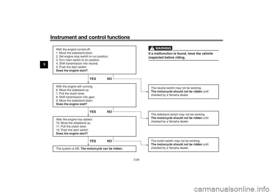
I g nition circuit cut-off systemThis system prevents in-gear engine
starts unless the clutch lever is pulled
and the sidestand is up. Also, it will
stop the running engine should the
sidestand be lowered while the trans-
mission is in gear.
Periodically check the system via the
following procedure.TIP This check is most reliable if per-
formed with a warmed-up engine.
See pages 3-2 and 3-13 for switch
operation information.
UBEHEAE0.book Page 28 Thursday, January 21, 2021 5:45 PM
Page 44 of 102
Instrument and control functions
3-29
3
With the engine turned off:
1. Move the sidestand down.
2. Set engine stop switch to run position.
3. Turn main switch to on position.
4. Shift transmission into neutral.
5. Push the start switch.
Does the engine start?
With the engine still running:
6. Move the sidestand up.
7. Pull the clutch lever.
8. Shift transmission into gear.
9. Move the sidestand down.
Does the engine stall?
After the engine has stalled:
10. Move the sidestand up.
11. Pull the clutch lever.
12. Push the start switch.
Does the engine start?
The system is OK. The motorcycle can be ridden.
YES NO YES NO YES NO
The neutral switch may not be working.
The motorcycle should not be ridden until
checked by a Yamaha dealer.
The clutch switch may not be working.
The motorcycle should not be ridden until
checked by a Yamaha dealer.The sidestand switch may not be working.
The motorcycle should not be ridden until
checked by a Yamaha dealer.If a malfunction is found, have the vehicle
inspected before riding.
WARNING
UBEHEAE0.book Page 29 Thursday, January 21, 2021 5:45 PM