fuse box YAMAHA TRACER 900 GT 2019 Owners Manual
[x] Cancel search | Manufacturer: YAMAHA, Model Year: 2019, Model line: TRACER 900 GT, Model: YAMAHA TRACER 900 GT 2019Pages: 120, PDF Size: 9.7 MB
Page 100 of 120
![YAMAHA TRACER 900 GT 2019 Owners Manual Periodic maintenance an d a djustment
6-31
6 connect the positive lea
d b efore
connectin g the ne gative lead .
[ECA16842]
4. After installation, make sure that
the battery leads are properly con-
ne YAMAHA TRACER 900 GT 2019 Owners Manual Periodic maintenance an d a djustment
6-31
6 connect the positive lea
d b efore
connectin g the ne gative lead .
[ECA16842]
4. After installation, make sure that
the battery leads are properly con-
ne](/img/51/51871/w960_51871-99.png)
Periodic maintenance an d a djustment
6-31
6 connect the positive lea
d b efore
connectin g the ne gative lead .
[ECA16842]
4. After installation, make sure that
the battery leads are properly con-
nected to the battery terminals.NOTICE
ECA16531
Always keep the b attery charged .
Storin g a d ischar ged battery can
cause permanent battery dama ge.
EAU63134
Replacin g the fusesThe fuse boxes and individual fuses
are located under the rider seat (see
page 3-34) and behind panel A (see
page 6-9).
To access fuse box 1, the main fuse,
and the fuel injection system fuse, re-
move the rider seat. (See page 3-34.)
TIPTo access the fuel injection system
fuse, remove the starter relay cover by
pulling it upward.
1. Fuse box 1
2. Main fuse
3. Fuel injection system fuse
4. Fuel injection system spare fuse1 3
4
2
1. Radiator fan motor fuse
2. Backup fuse (for clock and immobilizer sys- tem)
3. Electronic throttle valve fuse
4. ABS solenoid fuse
5. ABS motor fuse
6. Spare fuse
1
2
345
6
UB1JE1E0.book Page 31 Thursday, October 11, 2018 10:43 AM
Page 101 of 120

Periodic maintenance an d a djustment
6-32
6
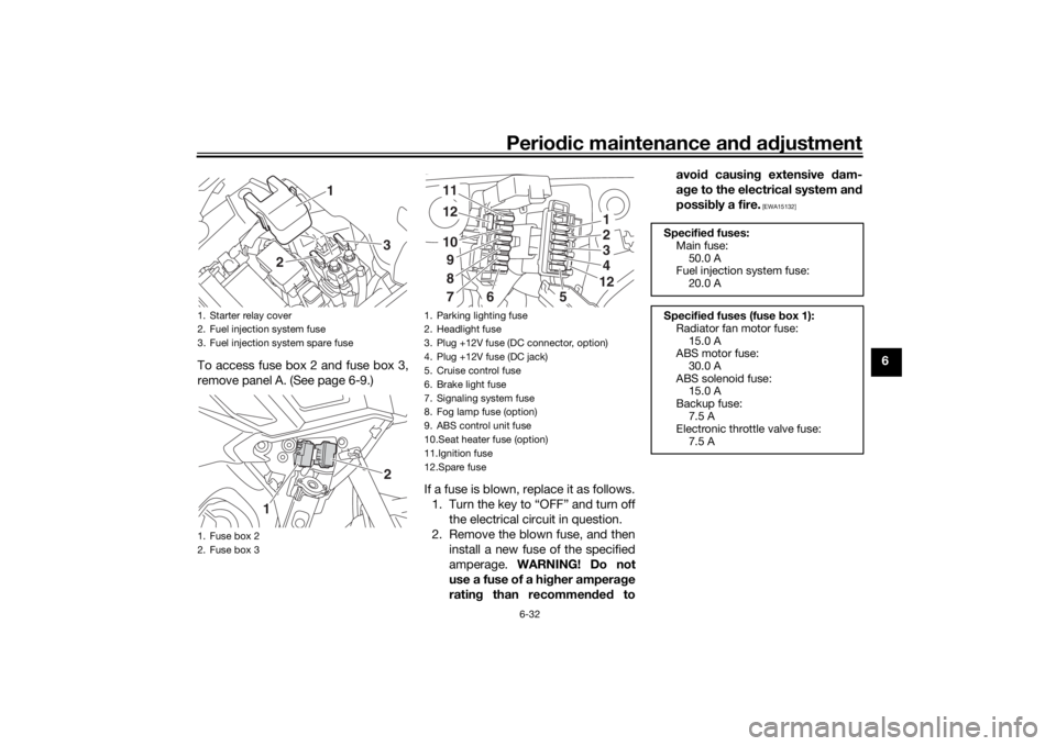
To access fuse box 2 and fuse box 3,
remove panel A. (See page 6-9.)
If a fuse is blown, replace it as follows.1. Turn the key to “OFF” and turn off the electrical circuit in question.
2. Remove the blown fuse, and then install a new fuse of the specified
amperage. WARNING! Do not
use a fuse of a hi gher ampera ge
ratin g than recommen ded to avoi
d causin g extensive dam-
a g e to the electrical system an d
possi bly a fire.
[EWA15132]
1. Starter relay cover
2. Fuel injection system fuse
3. Fuel injection system spare fuse
1. Fuse box 2
2. Fuse box 3
3
2
1
1
2
1. Parking lighting fuse
2. Headlight fuse
3. Plug +12V fuse (DC connector, option)
4. Plug +12V fuse (DC jack)
5. Cruise control fuse
6. Brake light fuse
7. Signaling system fuse
8. Fog lamp fuse (option)
9. ABS control unit fuse
10.Seat heater fuse (option)
11.Ignition fuse
12.Spare fuse
123412
111210987
6
5
Specified fuses:
Main fuse: 50.0 A
Fuel injection system fuse:
20.0 A
Specified fuses (fuse box 1):
Radiator fan motor fuse: 15.0 A
ABS motor fuse:
30.0 A
ABS solenoid fuse: 15.0 A
Backup fuse: 7.5 A
Electronic throttle valve fuse:
7.5 A
UB1JE1E0.book Page 32 Thursday, October 11, 2018 10:43 AM
Page 102 of 120

Periodic maintenance an d a djustment
6-33
6
3. Turn the key to “ON” and turn onthe electrical circuit in question to
check if the device operates.
4. If the fuse immediately blows again, have a Yamaha dealer
check the electrical system.
EAUN2261
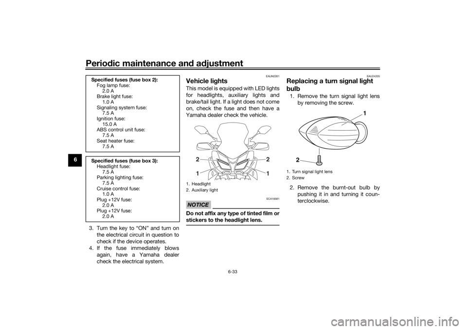
Vehicle lig htsThis model is equipped with LED lights
for headlights, auxiliary lights and
brake/tail light. If a light does not come
on, check the fuse and then have a
Yamaha dealer check the vehicle.NOTICE
ECA16581
Do not affix any type of tinte d film or
stickers to the hea dlig ht lens.
EAU24205
Replacin g a turn si gnal li ght
b ul b1. Remove the turn signal light lens
by removing the screw.
2. Remove the burnt-out bulb by pushing it in and turning it coun-
terclockwise.
Specifie d fuses (fuse box 2):
Fog lamp fuse:
2.0 A
Brake light fuse:
1.0 A
Signaling system fuse: 7.5 A
Ignition fuse: 15.0 A
ABS control unit fuse:
7.5 A
Seat heater fuse: 7.5 A
Specifie d fuses (fuse box 3):
Headlight fuse:
7.5 A
Parking lighting fuse: 7.5 A
Cruise control fuse: 1.0 A
Plug +12V fuse:
2.0 A
Plug +12V fuse: 2.0 A
1. Headlight
2. Auxiliary light
21
21
1. Turn signal light lens
2. Screw
1
2
UB1JE1E0.book Page 33 Thursday, October 11, 2018 10:43 AM