ECO mode YAMAHA TRACER 900 GT 2020 User Guide
[x] Cancel search | Manufacturer: YAMAHA, Model Year: 2020, Model line: TRACER 900 GT, Model: YAMAHA TRACER 900 GT 2020Pages: 120, PDF Size: 9.78 MB
Page 113 of 120

Consumer information
9-1
9
EAU53562
Id entification num bersRecord the vehicle identification num-
ber, engine serial number, and the
model label information in the spaces
provided below. These identification
numbers are needed when registering
the vehicle with the authorities in your
area and when ordering spare parts
from a Yamaha dealer.
VEHICLE IDENTIFICATION NUMBER:
ENGINE SERIAL NUMBER:
MODEL LABEL INFORMATION:
EAU26401
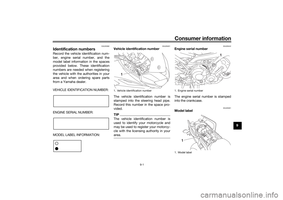
Vehicle i dentification num ber
The vehicle identification number is
stamped into the steering head pipe.
Record this number in the space pro-
vided.TIPThe vehicle identification number is
used to identify your motorcycle and
may be used to register your motorcy-
cle with the licensing authority in your
area.
EAU26442
En gine serial num ber
The engine serial number is stamped
into the crankcase.
EAU26461
Mo del la bel
1. Vehicle identification number
1
1. Engine serial number
1. Model label
1
1
UB1JE1E0.book Page 1 Thursday, October 11, 2018 10:43 AM
Page 114 of 120

Consumer information
9-2
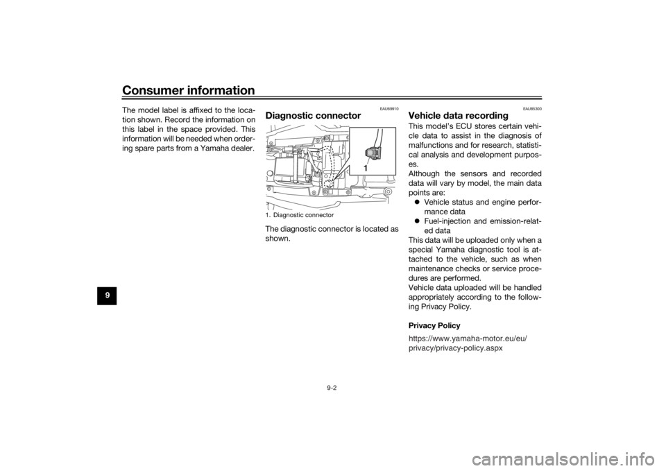
9The model label is affixed to the loca-
tion shown. Record the information on
this label in the space provided. This
information will be needed when order-
ing spare parts from a Yamaha dealer.
EAU69910
Dia
gnostic connectorThe diagnostic connector is located as
shown.
EAU85300
Vehicle data recor din gThis model’s ECU stores certain vehi-
cle data to assist in the diagnosis of
malfunctions and for research, statisti-
cal analysis and development purpos-
es.
Although the sensors and recorded
data will vary by model, the main data
points are:
Vehicle status and engine perfor-
mance data
Fuel-injection and emission-relat-
ed data
This data will be uploaded only when a
special Yamaha diagnostic tool is at-
tached to the vehicle, such as when
maintenance checks or service proce-
dures are performed.
Vehicle data uploaded will be handled
appropriately according to the follow-
ing Privacy Policy.
Privacy Policy
1. Diagnostic connector
1
https://www.yamaha-motor.eu/eu/
privacy/privacy-policy.aspx
UB1JE1E0.book Page 2 Thursday, October 11, 2018 10:43 AM
Page 116 of 120

10-1
10
IndexAABS ....................................................... 3-27
ABS warning light ................................... 3-6
Air filter element .................................... 6-15
Auxiliary DC connector ......................... 3-44
Auxiliary DC jack ................................... 3-43BBattery .................................................. 6-30
Brake and clutch levers, checking
and lubricating .................................... 6-27
Brake and shift pedals, checking and lubricating ........................................... 6-26
Brake fluid, changing ............................ 6-23
Brake fluid level, checking .................... 6-21
Brake lever ............................................ 3-26
Brake lever free play, checking............. 6-20
Brake light switches.............................. 6-20
Brake pedal........................................... 3-27CCables, checking and lubricating ......... 6-25
Canister................................................. 6-11
Care ........................................................ 7-1
Catalytic converter ................................ 3-33
Centerstand and sidestand, checking and lubricating .................................... 6-27
Clutch lever ........................................... 3-25
Clutch lever free play, adjusting ........... 6-19
Coolant ................................................. 6-14
Cruise control indicator lights ................. 3-6
Cruise control switches .......................... 3-4
Cruise control system ............................. 3-8DData recording, vehicle ........................... 9-2
Diagnostic connector.............................. 9-2 Dimmer/Pass switch .............................. 3-4
Display, main screen ............................ 3-11
Display, menu screen ........................... 3-15
D-mode (drive mode) ........................... 3-25
Drive chain, cleaning and lubricating ... 6-25
Drive chain slack .................................. 6-23
Drive mode switch.................................. 3-4
EEngine break-in ...................................... 5-4
Engine idling speed, checking ............. 6-15
Engine oil .............................................. 6-11
Engine oil and Coolant warning light ...... 3-7
Engine serial number .............................. 9-1
Engine trouble warning light ................... 3-6FFront and rear brake pads, checking ... 6-21
Front fork, adjusting ............................. 3-39
Front fork, checking ............................. 6-28
Fuel ....................................................... 3-31
Fuel consumption, tips for reducing ...... 5-4
Fuel tank cap ........................................ 3-30
Fuel tank overflow hose ....................... 3-33
Fuses, replacing ................................... 6-31HHandlebar position, adjusting .............. 3-39
Handlebar switches ................................ 3-3
Hazard switch......................................... 3-4
Headlight beams, adjusting.................. 3-38
Helmet holder ....................................... 3-37
High beam indicator light ....................... 3-6
Horn switch ............................................ 3-4IIdentification numbers ............................ 9-1
Ignition circuit cut-off system ............... 3-45Immobilizer system .................................3-1
Immobilizer system indi
cator light ..........3-7
Indicator lights and warning lights ..........3-5
LLicense plate light bulb, replacing ........6-34MMain switch/steering lock .......................3-2
Maintenance and lubrication, periodic....6-5
Maintenance, emission control system ..................................................6-3
Matte color, caution ................................7-1
Model label .............................................9-1NNeutral indicator light ..............................3-6PPanel, removing and installing ................6-9
Parking ....................................................5-5
Part locations ..........................................2-1QQuick shift system ................................3-26RRider seat height, adjusting ..................3-35SSafety information ...................................1-1
Seats .....................................................3-34
Shift indicator light ..................................3-7
Shifting ....................................................5-2
Shift pedal .............................................3-26
Shock absorber assembly, adjusting ....3-41
Sidestand ..............................................3-44
Spark plugs, checking ..........................6-10
Specifications .........................................8-1
Starting the engine ..................................5-1
Steering, checking ................................6-29
UB1JE1E0.book Page 1 Thursday, October 11, 2018 10:43 AM