display YAMAHA TRACER 900 GT 2020 User Guide
[x] Cancel search | Manufacturer: YAMAHA, Model Year: 2020, Model line: TRACER 900 GT, Model: YAMAHA TRACER 900 GT 2020Pages: 120, PDF Size: 9.78 MB
Page 34 of 120
Instrument and control functions
3-19
3
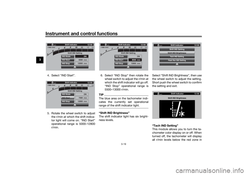
4. Select “IND Start”.
5. Rotate the wheel switch to adjustthe r/min at which the shift indica-
tor light will come on. “IND Start”
operational range is 5000–12800
r/min. 6. Select “IND Stop” then rotate the
wheel switch to adjust the r/min at
which the shift indicator will go off.
“IND Stop” operational range is
5500–13000 r/min.
TIPThe blue area on the tachometer indi-
cates the currently set operational
range of the shift indicator light.“Shift IND Bri ghtness”
The shift indicator light has six bright-
ness levels. Select “Shift IND Brightness”, then use
the wheel switch to adjust the setting.
Short push the wheel switch to confirm
the setting and exit.
“Tach IND Settin
g”
This module allows you to turn the ta-
chometer color display on or off. When
turned off, the tachometer will display
all r/min levels below the red zone in
1000 r/min
12 :
00
Shift IND Setting
IND Mode
IND Start
IND Stop ON
6000
r/min
12000
r/min
km/h
Shift Indicator
1000 r/min
12 :
00
Shift IND Setting
IND Mode
IND Start
IND Stop ON
7000
r/min
12000
r/min
km/h
Shift Indicator
1000 r/min
12 :
00
Shift IND Setting
IND Mode
IND Start
IND Stop ON
8000
r/min
13000
r/min
km/h
Shift Indicator
12 :
00
Shift Indicator
km/h
Tach IND SettingShift IND SettingPeak Rev IND SettingShift IND Brightness
12 :
00
Shift Indicator
km/h
Shift IND Bri ghtness
3
UB1JE1E0.book Page 19 Thursday, October 11, 2018 10:43 AM
Page 35 of 120

Instrument and control functions
3-20
3
black or white (depending on wallpa-
per settings). When turned on, the mid
and mid-to-high r/min zones can be
set to come on in green and then or-
ange colors.
1. Select “Tach IND Setting”.
2. Select “IND Mode”. 3. Select ON to turn the tachometer
color display mode on (or select
OFF to turn this function off).
4. Select “Tach IND 1st” to set the green zone starting r/min.
5. Set the starting r/min by rotating and then short pushing the wheel
switch. All r/min above this value up to the “Tach IND 2nd” setting
value (or the red zone), will be dis-
played in green.
TIPGreen bar start setting range: 5000–
11300 r/min.6. Select “Tach IND 2nd”.
12
:
00
Shift Indicator
km/h
Tach IND SettingShift IND SettingPeak Rev IND SettingShift IND Brightness
1000 r/min
12 :
00
km/h
Shift Indicator
Tach IND Setting
IND Mode ON
5000
r/min
8000
r/min
Tach IND 1st
Tach IND 2nd
1000 r/min
12 :
00
km/h
Shift Indicator
Tach IND Setting
IND Mode
ON
5000
r/min
8000
r/min
Tach IND 1st
Tach IND 2nd
1000 r/min
12 :
00
km/h
Shift Indicator
Tach IND Setting
IND Mode ON
5000
r/min
8000
r/min
Tach IND 1st
Tach IND 2nd
1000 r/min
12 :
00
km/h
Shift Indicator
Tach IND Setting
IND Mode ON
5000
r/min
8000
r/min
Tach IND 1st
Tach IND 2nd
1000 r/min
12 :
00
km/h
Shift Indicator
Tach IND Setting
IND Mode ON
5000
r/min
8000
r/min
Tach IND 1st
Tach IND 2nd
UB1JE1E0.book Page 20 Thursday, October 11, 2018 10:43 AM
Page 36 of 120
Instrument and control functions
3-21
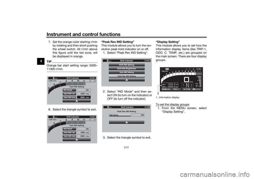
3 7. Set the orange color starting r/min
by rotating and then short pushing
the wheel switch. All r/min above
this figure until the red zone, will
be displayed in orange.
TIPOrange bar start setting range: 5000–
11300 r/min.8. Select the triangle symbol to exit. “Peak Rev IND Settin
g”
This module allows you to turn the rev-
olution peak hold indicator on or off. 1. Select “Peak Rev IND Setting”.
2. Select “IND Mode” and then se- lect ON (to turn on the indicator) or
OFF (to turn off the indicator).
3. Select the triangle symbol to exit. “Display Setting
”
This module allows you to set how the
information display items (like TRIP-1,
ODO, C. TEMP, etc.) are grouped on
the main screen. There are four display
groups.
To set the display groups
1. From the MENU screen, select “Display Setting”.
1000 r/min
12:
00
km/h
Shift Indicator
Tach IND Setting
IND Mode ON
5000
r/min
8000
r/min
Tach IND 1st
Tach IND 2nd
1000 r/min
12 :
00
km/h
Shift Indicator
Tach IND Setting
IND Mode ON
5000
r/min
8000
r/min
Tach IND 1st
Tach IND 2nd
12 :
00
Shift Indicator
km/h
Tach IND SettingShift IND SettingPeak Rev IND SettingShift IND BrightnessPeak Rev IND Setting
IND Mode
ON
Shift Indicator
km/h
GPS
12 :
00
1. Information display
km
TRIP-2
TRIP-1
1234.5 1234.5
km
1N
2km/h
1000 r/min
QS
12
:
00 EECOF2/1
MODE-
STD
TCS 1
In °C 25
1
UB1JE1E0.book Page 21 Thursday, October 11, 2018 10:43 AM
Page 37 of 120
Instrument and control functions
3-22
3
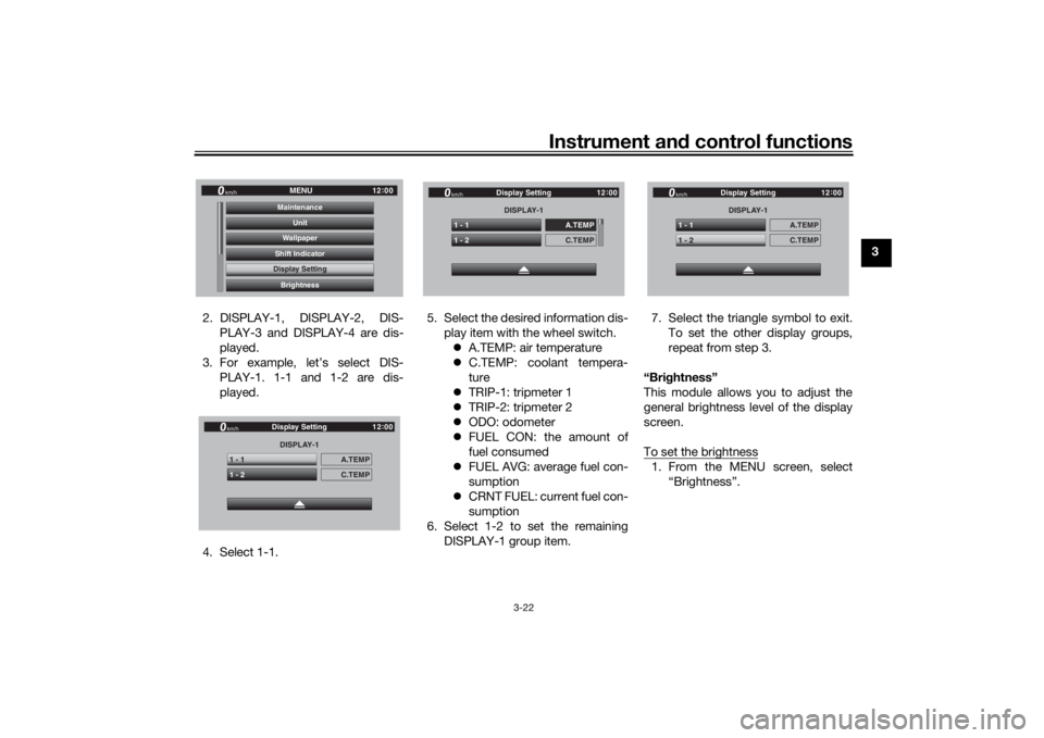
2. DISPLAY-1, DISPLAY-2, DIS- PLAY-3 and DISPLAY-4 are dis-
played.
3. For example, let’s select DIS- PLAY-1. 1-1 and 1-2 are dis-
played.
4. Select 1-1. 5. Select the desired information dis-
play item with the wheel switch. A.TEMP: air temperature
C.TEMP: coolant tempera-
ture
TRIP-1: tripmeter 1
TRIP-2: tripmeter 2
ODO: odometer
FUEL CON: the amount of
fuel consumed
FUEL AVG: average fuel con-
sumption
CRNT FUEL: current fuel con-
sumption
6. Select 1-2 to set the remaining DISPLAY-1 group item. 7. Select the triangle symbol to exit.
To set the other display groups,
repeat from step 3.
“Brig htness”
This module allows you to adjust the
general brightness level of the display
screen.
To set the brightness
1. From the MENU screen, select “Brightness”.
12:
00
MENU
km/h
BrightnessDisplay SettingShift IndicatorWallpaperUnit
MaintenanceDisplay SettingDISPLAY-1
1 - 1
A.TEMP
1 - 2
C.TEMP
Display Setting
km/h
GPS
12 :
00
DISPLAY-1
1 - 1
A.TEMP
1 - 2
C.TEMP
Display Setting
km/h
GPS
12 :
00
DISPLAY-1
1 - 1
A.TEMP
1 - 2
C.TEMP
Display Setting
km/h
GPS
12 :
00
UB1JE1E0.book Page 22 Thursday, October 11, 2018 10:43 AM
Page 38 of 120
Instrument and control functions
3-23
3
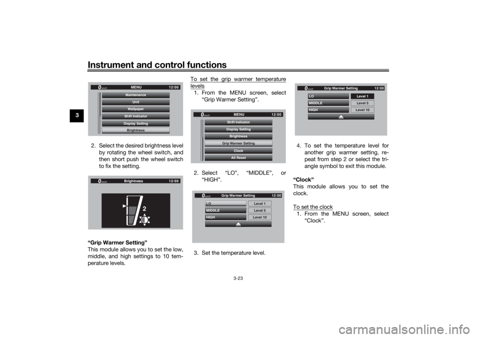
2. Select the desired brightness levelby rotating the wheel switch, and
then short push the wheel switch
to fix the setting.
“Grip Warmer Settin g”
This module allows you to set the low,
middle, and high settings to 10 tem-
perature levels. To set the grip warmer temperature
levels1. From the MENU screen, select
“Grip Warmer Setting”.
2. Select “LO”, “MIDDLE”, or “HIGH”.
3. Set the temperature level. 4. To set the temperature level for
another grip warmer setting, re-
peat from step 2 or select the tri-
angle symbol to exit this module.
“Clock”
This module allows you to set the
clock.
To set the clock
1. From the MENU screen, select “Clock”.
12:
00
MENU
km/h
BrightnessDisplay SettingShift IndicatorWallpaperUnit
MaintenanceBrightness
12 :
00
km/h
Brightness
2
12 :
00
MENU
km/h
All ResetClock
Grip Warmer Setting
BrightnessDisplay SettingShift IndicatorGrip Warmer Setting
HIGH LO
MIDDLE
Level 5Level 1
Level 10
km/h
GPS
12 :
00
Grip Warmer Setting
HIGH LO
MIDDLEkm/h
GPS
12 :
00
Level 5 Level 1
Level 10
Grip Warmer Setting
UB1JE1E0.book Page 23 Thursday, October 11, 2018 10:43 AM
Page 39 of 120
Instrument and control functions
3-24
3
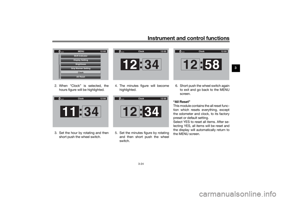
2. When “Clock” is selected, the hours figure will be highlighted.
3. Set the hour by rotating and then short push the wheel switch. 4. The minutes figure will become
highlighted.
5. Set the minutes figure by rotating and then short push the wheel
switch. 6. Short push the wheel switch again
to exit and go back to the MENU
screen.
“All Reset”
This module contains the all reset func-
tion which resets everything, except
the odometer and clock, to its factory
preset or default setting.
Select YES to reset all items. After se-
lecting YES, all items will be reset and
the display will automatically return to
the MENU screen.
12 :
00
MENU
km/h
All ResetClock
Grip Warmer Setting
BrightnessDisplay SettingShift Indicator
Clock
12 :
00
Clock
km/h11 34
:
12 :
00
Clock
km/h12 34
:
12 :
00
Clock
km/h12 34
:
12 :
00
Clock
km/h12 58
:
UB1JE1E0.book Page 24 Thursday, October 11, 2018 10:43 AM
Page 43 of 120
Instrument and control functions
3-28
3
EAU84342
Traction control systemThe traction control system (TCS)
helps maintain traction when acceler-
ating on slippery surfaces, such as un-
paved or wet roads. If sensors detect
that the rear wheel is starting to slip
(uncontrolled spinning), the traction
control system assists by regulating
engine power as needed until traction
is restored.
WARNING
EWA15433
The traction control system is not a
su bstitute for ri din g appropriately
for the con ditions. Traction control
cannot prevent loss of traction d ue
to excessive spee d when enterin g
turns, when acceleratin g har d at a
sharp lean an gle, or while brakin g,
an d cannot prevent front wheel slip-
pin g. As with any vehicle, approach
surfaces that may be slippery with
caution an d avoi d especially slip-
pery surfaces.
The “ ” indicator light flashes when
traction control has engaged. You may
notice slight changes in engine and ex-
haust sounds when the system has en-
gaged.
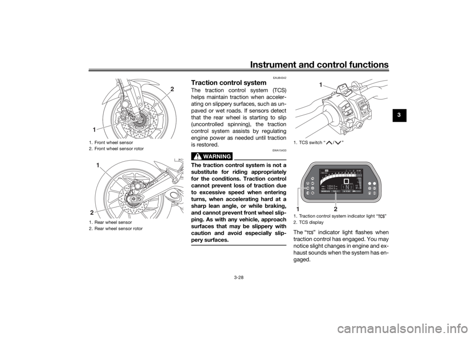
1. Front wheel sensor
2. Front wheel sensor rotor
1. Rear wheel sensor
2. Rear wheel sensor rotor1
2
1
2
1. TCS switch “ / ”
1. Traction control system indicator light “ ”
2. TCS display
1
km
TRIP-2 TRIP-1
1234.5 1234.5
km
1N2km/h
1000 r/minQS
12 :
00 EECOF2/1
MODE-STD
TCS 1
In °C 25
1
2
UB1JE1E0.book Page 28 Thursday, October 11, 2018 10:43 AM
Page 44 of 120
Instrument and control functions
3-29
3 The “ ” indicator light comes on
when traction control has been turned
off.
The TCS display indicates the current
TCS setting. There are three settings.
TCS “OFF”
: Turns the traction control
system off.
TCS “1” : Minimizes traction control
system assist.
TCS “2” : Maximizes traction control
assist; wheel spin is most strongly con-
trolled.
TIP When the vehicle is turned on,
traction control is turned on and
set to “1” or “2” (whichever was
last selected).
Turn the traction control system
off to help free the rear wheel if the
vehicle gets stuck in mud, sand, or
other soft surfaces.
NOTICE
ECA16801
Use only the specifie d tires. (See
pa ge 6-16.) Usin g different size d
tires will prevent the traction control
system from controllin g tire rotation
accurately.Setting the traction control system
WARNING
EWA15441
Be sure to stop the vehicle before
makin g any settin g chan ges to the
traction control system. Chan gin g
settin gs while ri din g can d istract the
operator an d increase the risk of an
acci dent.TCS settings can be changed only
when the vehicle is stopped and the
throttle closed.
Push the TCS switch “ ” to
change the TCS setting to TCS
“1” and push the TCS switch “ ”
to change the TCS setting to TCS
“2”.
Push the TCS switch “ ” for two
seconds to turn the traction con-
trol system off.
Push the TCS switch “ ” to turn
traction control back on (TCS will
return to the previous setting).
Resettin g the traction control sys-
tem
The traction control system will auto-
matically disable when: the front wheel or rear wheel
comes off the ground while riding.
excessive rear wheel spin is de-
tected while riding.
either wheel is rotated with the
main switch turned on (such as
when performing maintenance).
If the traction control system is dis-
abled, both the “ ” indicator light and
the “ ” warning light will come on.
UB1JE1E0.book Page 29 Thursday, October 11, 2018 10:43 AM
Page 45 of 120
Instrument and control functions
3-30
3
Should this occur, try resetting the sys-
tem as follows. 1. Stop the vehicle and turn the main switch off.
2. Wait a few seconds and then turn the main switch on.
3. The “ ” indicator light should turn off and the system be en-
abled.
TIPIf the “ ” indicator light remains on af-
ter resetting, the vehicle may still be
ridden; however, have a Yamaha deal-
er check the vehicle as soon as possi-
ble.
4. Have a Yamaha dealer check thevehicle and turn off the “ ”
warning light.
EAU13076
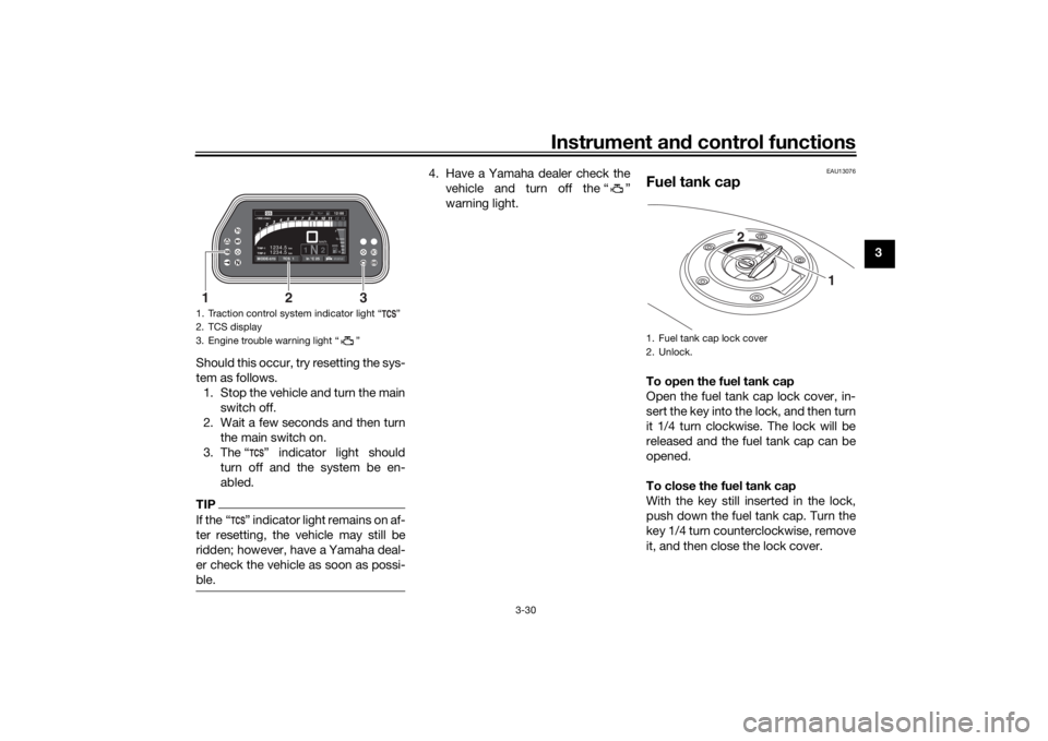
Fuel tank capTo open the fuel tank cap
Open the fuel tank cap lock cover, in-
sert the key into the lock, and then turn
it 1/4 turn clockwise. The lock will be
released and the fuel tank cap can be
opened.
To close the fuel tank cap
With the key still inserted in the lock,
push down the fuel tank cap. Turn the
key 1/4 turn counterclockwise, remove
it, and then close the lock cover.
1. Traction control system indicator light “ ”
2. TCS display
3. Engine trouble warning light “ ”
km
TRIP-2 TRIP-1
1234.5 1234.5
km
1N2km/h
1000 r/minQS
12:
00 EECOF2/1
MODE-STD
TCS 1
In °C 25
3
1
2
1. Fuel tank cap lock cover
2. Unlock.
1
2
UB1JE1E0.book Page 30 Thursday, October 11, 2018 10:43 AM
Page 116 of 120

10-1
10
IndexAABS ....................................................... 3-27
ABS warning light ................................... 3-6
Air filter element .................................... 6-15
Auxiliary DC connector ......................... 3-44
Auxiliary DC jack ................................... 3-43BBattery .................................................. 6-30
Brake and clutch levers, checking
and lubricating .................................... 6-27
Brake and shift pedals, checking and lubricating ........................................... 6-26
Brake fluid, changing ............................ 6-23
Brake fluid level, checking .................... 6-21
Brake lever ............................................ 3-26
Brake lever free play, checking............. 6-20
Brake light switches.............................. 6-20
Brake pedal........................................... 3-27CCables, checking and lubricating ......... 6-25
Canister................................................. 6-11
Care ........................................................ 7-1
Catalytic converter ................................ 3-33
Centerstand and sidestand, checking and lubricating .................................... 6-27
Clutch lever ........................................... 3-25
Clutch lever free play, adjusting ........... 6-19
Coolant ................................................. 6-14
Cruise control indicator lights ................. 3-6
Cruise control switches .......................... 3-4
Cruise control system ............................. 3-8DData recording, vehicle ........................... 9-2
Diagnostic connector.............................. 9-2 Dimmer/Pass switch .............................. 3-4
Display, main screen ............................ 3-11
Display, menu screen ........................... 3-15
D-mode (drive mode) ........................... 3-25
Drive chain, cleaning and lubricating ... 6-25
Drive chain slack .................................. 6-23
Drive mode switch.................................. 3-4
EEngine break-in ...................................... 5-4
Engine idling speed, checking ............. 6-15
Engine oil .............................................. 6-11
Engine oil and Coolant warning light ...... 3-7
Engine serial number .............................. 9-1
Engine trouble warning light ................... 3-6FFront and rear brake pads, checking ... 6-21
Front fork, adjusting ............................. 3-39
Front fork, checking ............................. 6-28
Fuel ....................................................... 3-31
Fuel consumption, tips for reducing ...... 5-4
Fuel tank cap ........................................ 3-30
Fuel tank overflow hose ....................... 3-33
Fuses, replacing ................................... 6-31HHandlebar position, adjusting .............. 3-39
Handlebar switches ................................ 3-3
Hazard switch......................................... 3-4
Headlight beams, adjusting.................. 3-38
Helmet holder ....................................... 3-37
High beam indicator light ....................... 3-6
Horn switch ............................................ 3-4IIdentification numbers ............................ 9-1
Ignition circuit cut-off system ............... 3-45Immobilizer system .................................3-1
Immobilizer system indi
cator light ..........3-7
Indicator lights and warning lights ..........3-5
LLicense plate light bulb, replacing ........6-34MMain switch/steering lock .......................3-2
Maintenance and lubrication, periodic....6-5
Maintenance, emission control system ..................................................6-3
Matte color, caution ................................7-1
Model label .............................................9-1NNeutral indicator light ..............................3-6PPanel, removing and installing ................6-9
Parking ....................................................5-5
Part locations ..........................................2-1QQuick shift system ................................3-26RRider seat height, adjusting ..................3-35SSafety information ...................................1-1
Seats .....................................................3-34
Shift indicator light ..................................3-7
Shifting ....................................................5-2
Shift pedal .............................................3-26
Shock absorber assembly, adjusting ....3-41
Sidestand ..............................................3-44
Spark plugs, checking ..........................6-10
Specifications .........................................8-1
Starting the engine ..................................5-1
Steering, checking ................................6-29
UB1JE1E0.book Page 1 Thursday, October 11, 2018 10:43 AM