warning YAMAHA TRACER 900 GT 2020 User Guide
[x] Cancel search | Manufacturer: YAMAHA, Model Year: 2020, Model line: TRACER 900 GT, Model: YAMAHA TRACER 900 GT 2020Pages: 120, PDF Size: 9.78 MB
Page 26 of 120
Instrument and control functions
3-11
3 ing speed. If this occurs, acceler-
ate to the desired traveling speed
using the throttle.
When the vehicle is traveling
downhill, the actual traveling
speed may become higher than
the set cruising speed. If this oc-
curs, the setting switch cannot be
used to adjust the set cruising
speed. To reduce the traveling
speed, apply the brakes. When
the brakes are applied, the cruise
control system will become deac-
tivated.
EAU84301
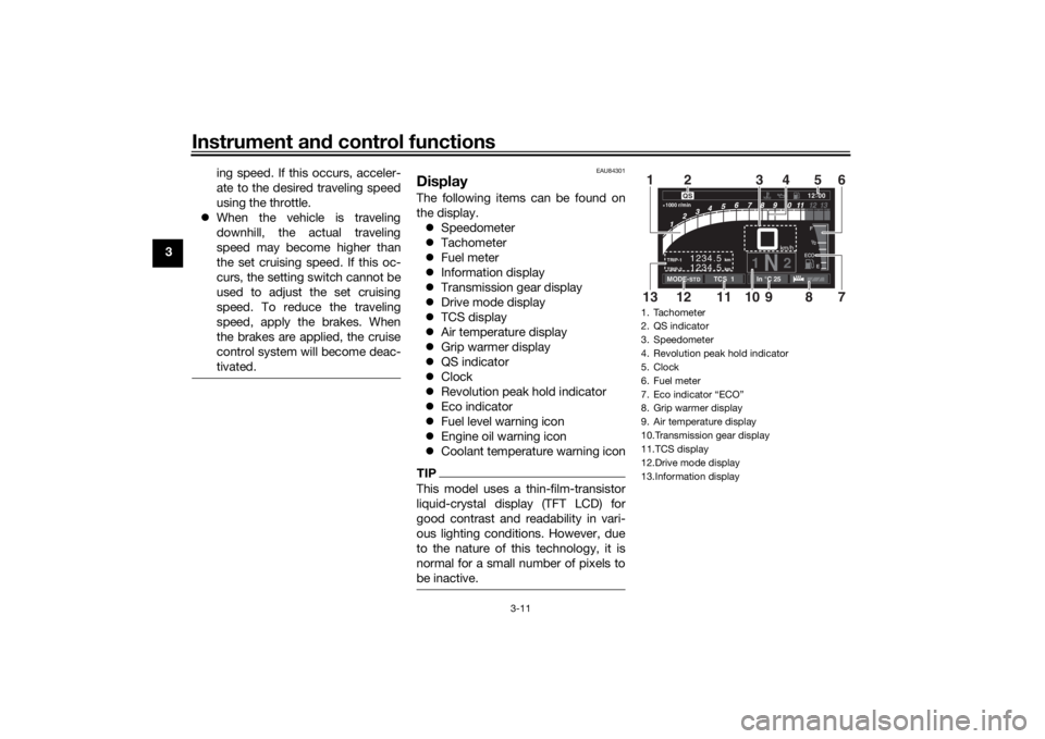
DisplayThe following items can be found on
the display.
Speedometer
Tachometer
Fuel meter
Information display
Transmission gear display
Drive mode display
TCS display
Air temperature display
Grip warmer display
QS indicator
Clock
Revolution peak hold indicator
Eco indicator
Fuel level warning icon
Engine oil warning icon
Coolant temperature warning iconTIPThis model uses a thin-film-transistor
liquid-crystal display (TFT LCD) for
good contrast and readability in vari-
ous lighting conditions. However, due
to the nature of this technology, it is
normal for a small number of pixels to
be inactive.
1. Tachometer
2. QS indicator
3. Speedometer
4. Revolution peak hold indicator
5. Clock
6. Fuel meter
7. Eco indicator “ECO”
8. Grip warmer display
9. Air temperature display
10.Transmission gear display
11.TCS display
12.Drive mode display
13.Information display
km
TRIP-2
TRIP-1
1234.5 1234.5
km
1N
2km/h
1000 r/min
QS
12
:
00 EECOF2/1
MODE-
STD
TCS 1
In °C 25
7
10
13
8
9
11
12
1
6
4
2
5
3
UB1JE1E0.book Page 11 Thursday, October 11, 2018 10:43 AM
Page 27 of 120
Instrument and control functions
3-12
3
WARNING
EWA18210
Stop the vehicle before makin g any
settin g chan ges. Chan gin g settin gs
while ri din g can distract the opera-
tor an d increase the risk of an acci-
d ent.Spee dometer
The speedometer shows the vehicle’s
traveling speed.TIPThe display can be set to miles or kilo-
meters. Use the “Unit” module on the
MENU screen.Tachometer
The tachometer shows the engine
speed, as measured by the rotational
velocity of the crankshaft, in revolu-
tions per minute (r/min). When the ve-
hicle is first powered on, the
tachometer will sweep across the r/min
range and then return to zero.
TIPThe tachometer can be color-adjusted
and has a revolution peak hold indica-
tor which can be turned on or off.NOTICE
ECA10032
Do not operate the en gine in the ta-
chometer red zone.
Re d zone: 11250 r/min an d a boveFuel meter
The fuel meter indicates the amount of
fuel in the fuel tank. The display seg-
ments of the fuel meter disappear from
“F” (full) towards “E” (empty) as the fuel
level decreases.
When the last segment starts flashing
and the fuel level warning icon comes
on, refuel as soon as possible.TIPIf all the fuel meter display segments
flash repeatedly, have a Yamaha deal-
er check the related circuits.Clock
The clock uses a 12-hour time system. Information
display
This section of the main screen is used
to show additional riding related infor-
mation such as air and coolant temper-
ature readings, tripmeters, and fuel
consumption statistics. The informa-
tion display items can be set into four
groups via the MENU screen.
The information display items are:
A.TEMP: air temperature
C.TEMP: coolant temperature
TRIP-1: tripmeter 1
TRIP-2: tripmeter 2
F-TRIP: fuel tripmeter
ODO: odometer
FUEL CON: the amount of fuel con-
sumed
FUEL AVG: average fuel consumption
CRNT FUEL: current fuel consumption
TIP ODO will lock at 999999.
TRIP-1 and TRIP-2 will reset and
continue counting after 9999.9
has been reached.
UB1JE1E0.book Page 12 Thursday, October 11, 2018 10:43 AM
Page 29 of 120
Instrument and control functions
3-14
3
Air temperature
display
This display indicates the air tempera-
ture from –9 °C to 50 °C in 1 °C incre-
ments.
TIP –9 °C will be displayed even if the
air temperature falls below –9 °C.
50 °C will be displayed even if the
ambient temperature climbs
above 50 °C.
The temperature displayed may
vary from the actual ambient tem-
perature.Grip warmer d isplay
The grip warmers can be used when
the engine is running. There are 4 grip
warmer settings.
To change the grip warmer setting1. Select the grip warmer display. 2. Short push the wheel switch, and
then rotate the wheel switch up or
down to change the setting while
the display is flashing. Short push
the wheel switch to confirm the
setting.
TIPEach grip warmer setting can be fine
tuned in “Grip Warmer Setting” (see
page 3-23).NOTICE
ECA17932
Be sure to wear g loves when
using the grip warmers.
Do not use the grip warmers in
warm weather.
If the han dle bar grip or throttle
g rip becomes worn or d am-
a g ed , stop usin g the g rip warm-
ers an d replace the grips.
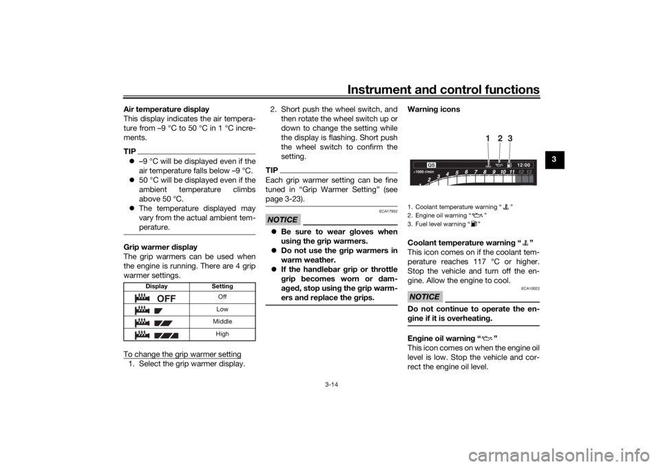
Warnin g icons
Coolant temperature warnin g“”
This icon comes on if the coolant tem-
perature reaches 117 °C or higher.
Stop the vehicle and turn off the en-
gine. Allow the engine to cool.NOTICE
ECA10022
Do not continue to operate the en-
g ine if it is overheatin g.En gine oil warnin g“”
This icon comes on when the engine oil
level is low. Stop the vehicle and cor-
rect the engine oil level.
Display Setting
Off
Low
Middle High
1. Coolant temperature warning “ ”
2. Engine oil warning “ ”
3. Fuel level warning “ ”1000 r/min
QS
12 :
00
2
3
1
UB1JE1E0.book Page 14 Thursday, October 11, 2018 10:43 AM
Page 30 of 120
Instrument and control functions
3-15
3 When the vehicle is turned on, this icon
will come on for a few seconds, and
then go off.
If a malfunction is detected, the oil level
warning icon will flash repeatedly.
Have a Yamaha dealer check the vehi-
cle.
NOTICE
ECA26400
Do not continue to operate the en-
g
ine if the oil level is low.Fuel level warnin g“”
This icon comes on when approxi-
mately 2.6 L (0.69 US gal, 0.57 Imp.gal)
of fuel remains in the tank.
If a malfunction is detected, the fuel
level warning icon will flash repeatedly.
Have a Yamaha dealer check the vehi-
cle.
EAU84311
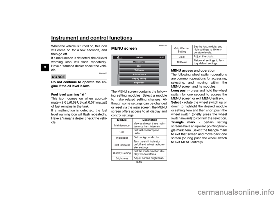
MENU screenThe MENU screen contains the follow-
ing setting modules. Select a module
to make related setting changes. Al-
though some settings can be changed
or reset via the main screen, the MENU
screen offers access to all display and
control settings. MENU access an
d operation
The following wheel switch operations
are common operations for accessing,
selecting, and moving within the
MENU screen and its modules.
Lon g push - press and hold the wheel
switch for one second to access the
MENU screen or exit MENU entirely.
Select - rotate the wheel switch up or
down to highlight the desired module
or setting item and then short push the
wheel switch (briefly press the wheel
switch inward) to confirm the selection.
Trian gle mark - certain setting
screens have an upward pointing trian-
gle mark item. Select the triangle mark
to exit that screen and move back one
screen (or long push the wheel switch
to exit MENU entirely).
Mo dule Description
View and reset three main-
tenance item intervals.
Set fuel consumption
units.
Set background color.
Turn the shift indicator
on/off and adjust tachom-
eter settings.
Set the multi-function dis-
play window items.
Adjust screen brightness.
12:
00
MENU
km/h
BrightnessDisplay SettingShift IndicatorWallpaperUnit
MaintenanceMaintenance
Maintenance
Unit
WallpaperShift IndicatorDisplay SettingBrightness
Set the low, middle, and
high settings to 10 tem-
perature levels.
Adjust the clock.
Return all settings to fac-
tory default settings.
Grip Warmer
Setting
ClockAll Reset
UB1JE1E0.book Page 15 Thursday, October 11, 2018 10:43 AM
Page 42 of 120
Instrument and control functions
3-27
3
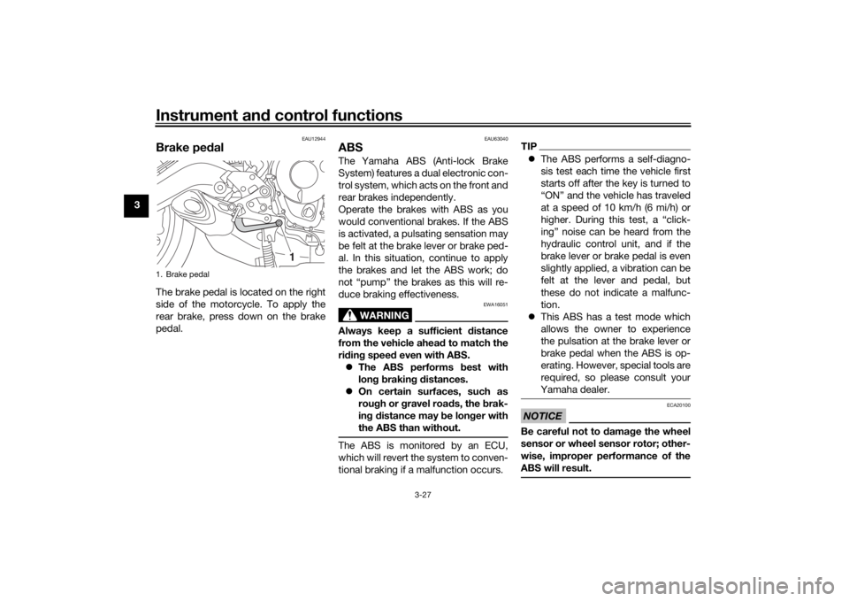
EAU12944
Brake ped alThe brake pedal is located on the right
side of the motorcycle. To apply the
rear brake, press down on the brake
pedal.
EAU63040
ABSThe Yamaha ABS (Anti-lock Brake
System) features a dual electronic con-
trol system, which acts on the front and
rear brakes independently.
Operate the brakes with ABS as you
would conventional brakes. If the ABS
is activated, a pulsating sensation may
be felt at the brake lever or brake ped-
al. In this situation, continue to apply
the brakes and let the ABS work; do
not “pump” the brakes as this will re-
duce braking effectiveness.
WARNING
EWA16051
Always keep a sufficient distance
from the vehicle ahea d to match the
ri din g spee d even with ABS.
The ABS performs best with
lon g b rakin g d istances.
On certain surfaces, such as
rou gh or g ravel roa ds, the b rak-
in g d istance may b e longer with
the ABS than without.The ABS is monitored by an ECU,
which will revert the system to conven-
tional braking if a malfunction occurs.
TIP The ABS performs a self-diagno-
sis test each time the vehicle first
starts off after the key is turned to
“ON” and the vehicle has traveled
at a speed of 10 km/h (6 mi/h) or
higher. During this test, a “click-
ing” noise can be heard from the
hydraulic control unit, and if the
brake lever or brake pedal is even
slightly applied, a vibration can be
felt at the lever and pedal, but
these do not indicate a malfunc-
tion.
This ABS has a test mode which
allows the owner to experience
the pulsation at the brake lever or
brake pedal when the ABS is op-
erating. However, special tools are
required, so please consult your
Yamaha dealer.NOTICE
ECA20100
Be careful not to d amage the wheel
sensor or wheel sensor rotor; other-
wise, improper performance of the
ABS will result.
1. Brake pedal
1
UB1JE1E0.book Page 27 Thursday, October 11, 2018 10:43 AM
Page 43 of 120
Instrument and control functions
3-28
3
EAU84342
Traction control systemThe traction control system (TCS)
helps maintain traction when acceler-
ating on slippery surfaces, such as un-
paved or wet roads. If sensors detect
that the rear wheel is starting to slip
(uncontrolled spinning), the traction
control system assists by regulating
engine power as needed until traction
is restored.
WARNING
EWA15433
The traction control system is not a
su bstitute for ri din g appropriately
for the con ditions. Traction control
cannot prevent loss of traction d ue
to excessive spee d when enterin g
turns, when acceleratin g har d at a
sharp lean an gle, or while brakin g,
an d cannot prevent front wheel slip-
pin g. As with any vehicle, approach
surfaces that may be slippery with
caution an d avoi d especially slip-
pery surfaces.
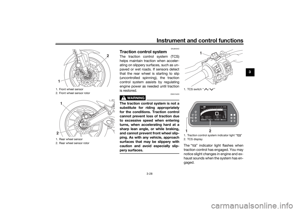
The “ ” indicator light flashes when
traction control has engaged. You may
notice slight changes in engine and ex-
haust sounds when the system has en-
gaged.
1. Front wheel sensor
2. Front wheel sensor rotor
1. Rear wheel sensor
2. Rear wheel sensor rotor1
2
1
2
1. TCS switch “ / ”
1. Traction control system indicator light “ ”
2. TCS display
1
km
TRIP-2 TRIP-1
1234.5 1234.5
km
1N2km/h
1000 r/minQS
12 :
00 EECOF2/1
MODE-STD
TCS 1
In °C 25
1
2
UB1JE1E0.book Page 28 Thursday, October 11, 2018 10:43 AM
Page 44 of 120
Instrument and control functions
3-29
3 The “ ” indicator light comes on
when traction control has been turned
off.
The TCS display indicates the current
TCS setting. There are three settings.
TCS “OFF”
: Turns the traction control
system off.
TCS “1” : Minimizes traction control
system assist.
TCS “2” : Maximizes traction control
assist; wheel spin is most strongly con-
trolled.
TIP When the vehicle is turned on,
traction control is turned on and
set to “1” or “2” (whichever was
last selected).
Turn the traction control system
off to help free the rear wheel if the
vehicle gets stuck in mud, sand, or
other soft surfaces.
NOTICE
ECA16801
Use only the specifie d tires. (See
pa ge 6-16.) Usin g different size d
tires will prevent the traction control
system from controllin g tire rotation
accurately.Setting the traction control system
WARNING
EWA15441
Be sure to stop the vehicle before
makin g any settin g chan ges to the
traction control system. Chan gin g
settin gs while ri din g can d istract the
operator an d increase the risk of an
acci dent.TCS settings can be changed only
when the vehicle is stopped and the
throttle closed.
Push the TCS switch “ ” to
change the TCS setting to TCS
“1” and push the TCS switch “ ”
to change the TCS setting to TCS
“2”.
Push the TCS switch “ ” for two
seconds to turn the traction con-
trol system off.
Push the TCS switch “ ” to turn
traction control back on (TCS will
return to the previous setting).
Resettin g the traction control sys-
tem
The traction control system will auto-
matically disable when: the front wheel or rear wheel
comes off the ground while riding.
excessive rear wheel spin is de-
tected while riding.
either wheel is rotated with the
main switch turned on (such as
when performing maintenance).
If the traction control system is dis-
abled, both the “ ” indicator light and
the “ ” warning light will come on.
UB1JE1E0.book Page 29 Thursday, October 11, 2018 10:43 AM
Page 45 of 120
Instrument and control functions
3-30
3
Should this occur, try resetting the sys-
tem as follows. 1. Stop the vehicle and turn the main switch off.
2. Wait a few seconds and then turn the main switch on.
3. The “ ” indicator light should turn off and the system be en-
abled.
TIPIf the “ ” indicator light remains on af-
ter resetting, the vehicle may still be
ridden; however, have a Yamaha deal-
er check the vehicle as soon as possi-
ble.
4. Have a Yamaha dealer check thevehicle and turn off the “ ”
warning light.
EAU13076
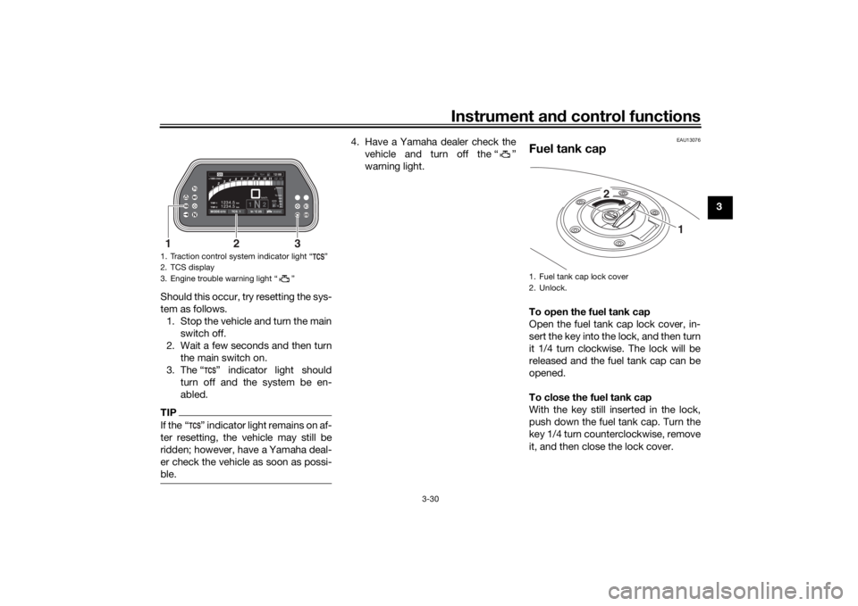
Fuel tank capTo open the fuel tank cap
Open the fuel tank cap lock cover, in-
sert the key into the lock, and then turn
it 1/4 turn clockwise. The lock will be
released and the fuel tank cap can be
opened.
To close the fuel tank cap
With the key still inserted in the lock,
push down the fuel tank cap. Turn the
key 1/4 turn counterclockwise, remove
it, and then close the lock cover.
1. Traction control system indicator light “ ”
2. TCS display
3. Engine trouble warning light “ ”
km
TRIP-2 TRIP-1
1234.5 1234.5
km
1N2km/h
1000 r/minQS
12:
00 EECOF2/1
MODE-STD
TCS 1
In °C 25
3
1
2
1. Fuel tank cap lock cover
2. Unlock.
1
2
UB1JE1E0.book Page 30 Thursday, October 11, 2018 10:43 AM
Page 46 of 120
Instrument and control functions
3-31
3
TIPThe fuel tank cap cannot be closed un-
less the key is in the lock. In addition,
the key cannot be removed if the cap is
not properly closed and locked.
WARNING
EWA11092
Make sure that the fuel tank cap is
properly close d after fillin g fuel.
Leakin g fuel is a fire hazar d.
EAU13222
FuelMake sure there is sufficient gasoline in
the tank.
WARNING
EWA10882
Gasoline an d g asoline vapors are
extremely flamma ble. To avoi d fires
an d explosions an d to re duce the
risk of injury when refuelin g, follow
these instructions.1. Before refueling, turn off the en- gine and be sure that no one is sit-
ting on the vehicle. Never refuel
while smoking, or while in the vi-
cinity of sparks, open flames, or
other sources of ignition such as
the pilot lights of water heaters
and clothes dryers.
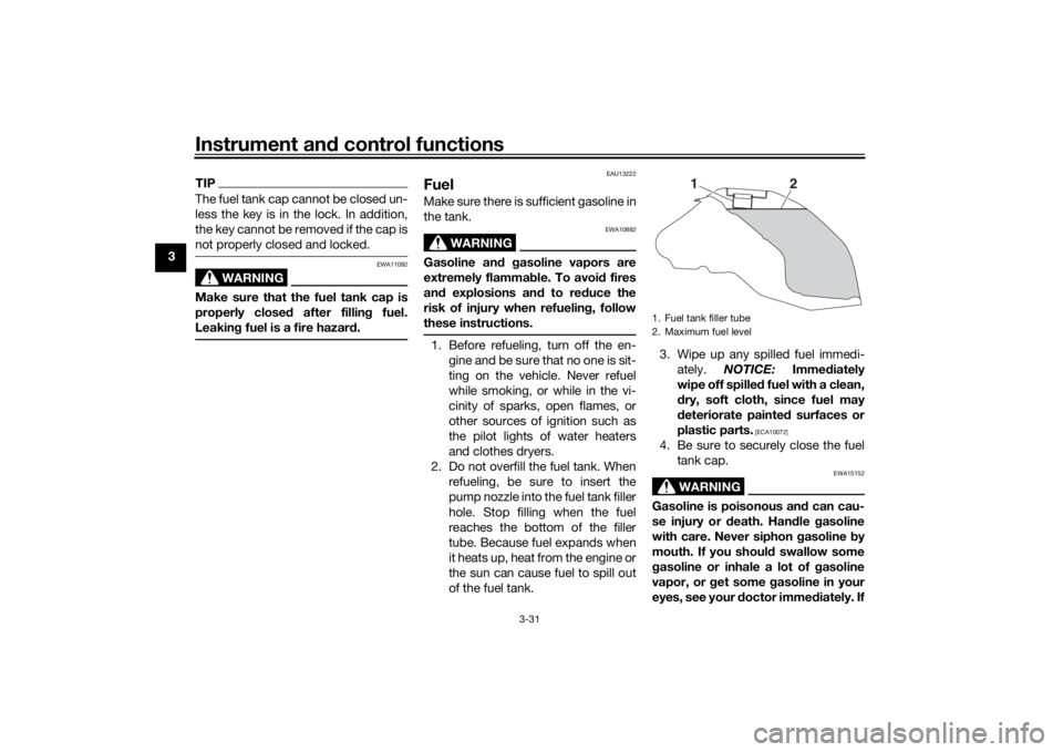
2. Do not overfill the fuel tank. When refueling, be sure to insert the
pump nozzle into the fuel tank filler
hole. Stop filling when the fuel
reaches the bottom of the filler
tube. Because fuel expands when
it heats up, heat from the engine or
the sun can cause fuel to spill out
of the fuel tank. 3. Wipe up any spilled fuel immedi-
ately. NOTICE: Immediately
wipe off spille d fuel with a clean,
d ry, soft cloth, since fuel may
d eteriorate painted surfaces or
plastic parts.
[ECA10072]
4. Be sure to securely close the fuel tank cap.
WARNING
EWA15152
Gasoline is poisonous an d can cau-
se injury or death. Han dle gasoline
with care. Never siphon gasoline by
mouth. If you shoul d swallow some
g asoline or inhale a lot of gasoline
vapor, or g et some gasoline in your
eyes, see your d octor immediately. If1. Fuel tank filler tube
2. Maximum fuel level
1
2
UB1JE1E0.book Page 31 Thursday, October 11, 2018 10:43 AM
Page 48 of 120
Instrument and control functions
3-33
3
EAU72972
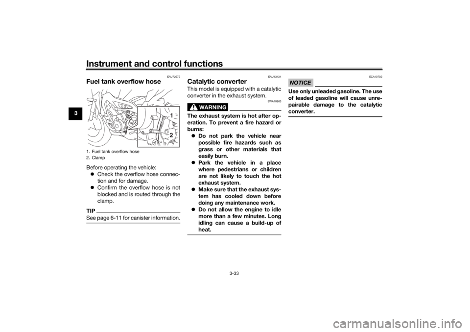
Fuel tank overflow hoseBefore operating the vehicle:
Check the overflow hose connec-
tion and for damage.
Confirm the overflow hose is not
blocked and is routed through the
clamp.TIPSee page 6-11 for canister information.
EAU13434
Catalytic converterThis model is equipped with a catalytic
converter in the exhaust system.
WARNING
EWA10863
The exhaust system is hot after op-
eration. To prevent a fire hazar d or
b urns:
Do not park the vehicle near
possi ble fire hazard s such as
g rass or other materials that
easily burn.
Park the vehicle in a place
where ped estrians or chil dren
are not likely to touch the hot
exhaust system.
Make sure that the exhaust sys-
tem has coole d down before
d oin g any maintenance work.
Do not allow the en gine to i dle
more than a few minutes. Lon g
i d lin g can cause a b uild-up of
heat.
NOTICE
ECA10702
Use only unlea ded g asoline. The use
of lead ed g asoline will cause unre-
pairab le damag e to the catalytic
converter.
1. Fuel tank overflow hose
2. Clamp
21
UB1JE1E0.book Page 33 Thursday, October 11, 2018 10:43 AM