brake fluid YAMAHA TRACER 900 GT 2020 Owners Manual
[x] Cancel search | Manufacturer: YAMAHA, Model Year: 2020, Model line: TRACER 900 GT, Model: YAMAHA TRACER 900 GT 2020Pages: 120, PDF Size: 9.78 MB
Page 6 of 120

Table of contentsSafety information ............................ 1-1
Description ....................................... 2-1
Left view ......................................... 2-1
Right view ....................................... 2-2
Controls and instruments ............... 2-3
Instrument an d control functions ... 3-1
Immobilizer system......................... 3-1
Main switch/steering lock............... 3-2
Handlebar switches ........................ 3-3
Indicator lights and warning lights............................................ 3-5
Cruise control system..................... 3-8
Display .......................................... 3-11
MENU screen ............................... 3-15
D-mode (drive mode).................... 3-25
Clutch lever .................................. 3-25
Shift pedal .................................... 3-26
Quick shift system ........................ 3-26
Brake lever.................................... 3-26
Brake pedal .................................. 3-27
ABS .............................................. 3-27
Traction control system ................ 3-28
Fuel tank cap ................................ 3-30
Fuel ............................................... 3-31
Fuel tank overflow hose ............... 3-33
Catalytic converter ....................... 3-33
Seats ............................................ 3-34
Adjusting the rider seat height...... 3-35
Helmet holder ............................... 3-37 Storage compartment ................... 3-38
Windshield ................................... 3-38
Adjusting the headlight beams ..... 3-38
Handlebar position ....................... 3-39
Adjusting the front fork ................. 3-39
Adjusting the shock absorber
assembly.................................... 3-41
Auxiliary DC jack ........................... 3-43
Auxiliary DC connector ................. 3-44
Sidestand ...................................... 3-44
Ignition circuit cut-off system ....... 3-45
For your safety – pre-operation
checks ............................................... 4-1
Operation an d important ri din g
points ................................................. 5-1
Starting the engine .......................... 5-1
Shifting ............................................ 5-2
Tips for reducing fuel consumption ................................ 5-4
Engine break-in ............................... 5-4
Parking ............................................ 5-5
Perio dic maintenance an d
a d justment ........................................ 6-1
Tool kit ............................................ 6-2
Periodic maintenance charts .......... 6-3
Periodic maintenance chart for the emission control system .............. 6-3 General maintenance and
lubrication chart .......................... 6-5
Removing and installing the panel............................................ 6-9
Checking the spark plugs ............. 6-10
Canister ........................................ 6-11
Engine oil ...................................... 6-11
Why Yamalube.............................. 6-13
Coolant ......................................... 6-14
Air filter element ............................ 6-15
Checking the engine idling
speed ........................................ 6-15
Checking the throttle grip free play ............................................ 6-16
Valve clearance............................. 6-16
Tires .............................................. 6-16
Cast wheels .................................. 6-19
Adjusting the clutch lever free play ............................................ 6-19
Checking the brake lever free
play ............................................ 6-20
Brake light switches ..................... 6-20
Checking the front and rear brake pads ................................ 6-21
Checking the brake fluid level ...... 6-21
Changing the brake fluid .............. 6-23
Drive chain slack........................... 6-23
Cleaning and lubricating the drive chain ................................. 6-25
Checking and lubricating the cables ........................................ 6-25UB1JE1E0.book Page 1 Thursday, October 11, 2018 10:43 AM
Page 14 of 120
Description
2-2
2
EAU10421
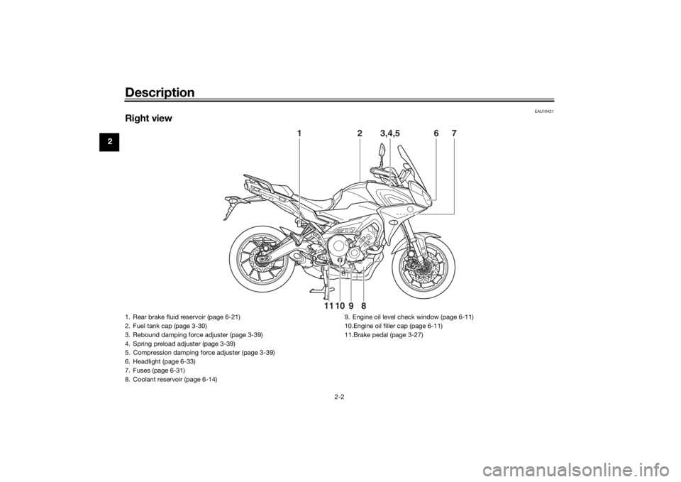
Right view
1
2
3,4,5
6
7
8
9
10
11
1. Rear brake fluid reservoir (page 6-21)
2. Fuel tank cap (page 3-30)
3. Rebound damping force adjuster (page 3-39)
4. Spring preload adjuster (page 3-39)
5. Compression damping force adjuster (page 3-39)
6. Headlight (page 6-33)
7. Fuses (page 6-31)
8. Coolant reservoir (page 6-14) 9. Engine oil level check window (page 6-11)
10.Engine oil filler cap (page 6-11)
11.Brake pedal (page 3-27)UB1JE1E0.book Page 2 Thursday, October 11, 2018 10:43 AM
Page 15 of 120
Description
2-3
2
EAU10431
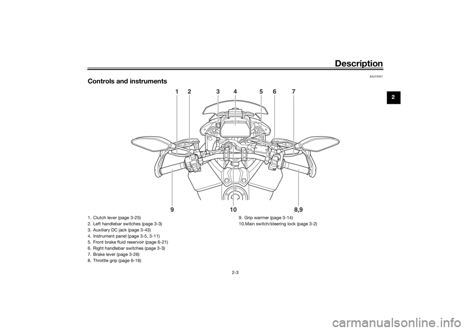
Controls and instruments
1
2
78,9
9
10
6
5
3
4
1. Clutch lever (page 3-25)
2. Left handlebar switches (page 3-3)
3. Auxiliary DC jack (page 3-43)
4. Instrument panel (page 3-5, 3-11)
5. Front brake fluid reservoir (page 6-21)
6. Right handlebar switches (page 3-3)
7. Brake lever (page 3-26)
8. Throttle grip (page 6-16) 9. Grip warmer (page 3-14)
10.Main switch/steering lock (page 3-2)
UB1JE1E0.book Page 3 Thursday, October 11, 2018 10:43 AM
Page 62 of 120
For your safety – pre-operation checks
4-1
4
EAU15599
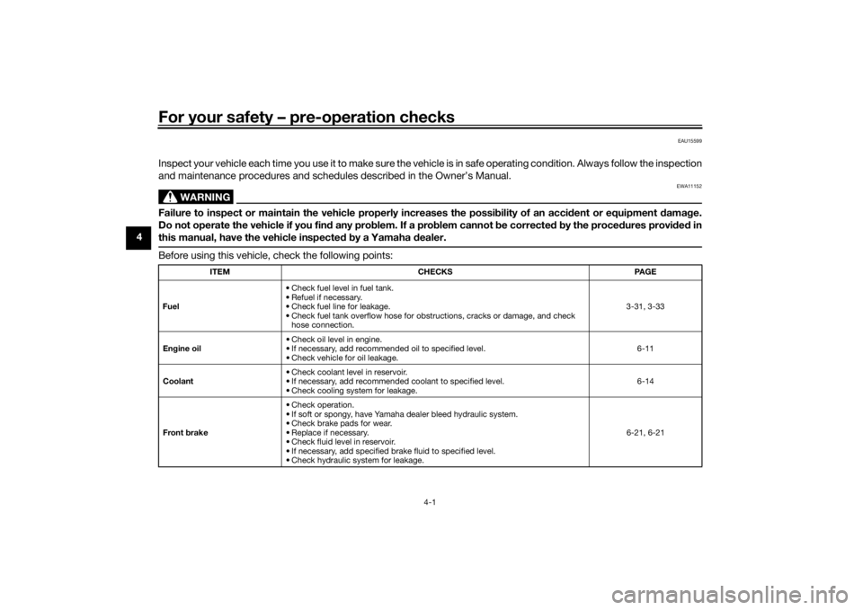
Inspect your vehicle each time you use it to make sure the vehicle is in safe operating condition. Always follow the inspection
and maintenance procedures and schedules described in the Owner’s Manual.
WARNING
EWA11152
Failure to inspect or maintain the vehicle properly increases the possibility of an acci dent or equipment damag e.
Do not operate the vehicle if you fin d any pro blem. If a pro blem cannot be corrected b y the proce dures provi ded in
this manual, have the vehicle inspecte d b y a Yamaha dealer.Before using this vehicle, check the following points:
ITEM CHECKS PAGE
Fuel • Check fuel level in fuel tank.
• Refuel if necessary.
• Check fuel line for leakage.
• Check fuel tank overflow hose for obstructions, cracks or damage, and check
hose connection. 3-31, 3-33
En gine oil • Check oil level in engine.
• If necessary, add recommended oil to specified level.
• Check vehicle for oil leakage. 6-11
Coolant • Check coolant level in reservoir.
• If necessary, add recommended coolant to specified level.
• Check cooling system for leakage. 6-14
Front brake • Check operation.
• If soft or spongy, have Yamaha dealer bleed hydraulic system.
• Check brake pads for wear.
• Replace if necessary.
• Check fluid level in reservoir.
• If necessary, add specified brake fluid to specified level.
• Check hydraulic system for leakage. 6-21, 6-21
UB1JE1E0.book Page 1 Thursday, October 11, 2018 10:43 AM
Page 63 of 120

For your safety – pre-operation checks
4-2
4
Rear brake • Check operation.
• If soft or spongy, have Yamaha dealer bleed hydraulic system.
• Check brake pads for wear.
• Replace if necessary.
• Check fluid level in reservoir.
• If necessary, add specified brake fluid to specified level.
• Check hydraulic system for leakage. 6-21, 6-21
Clutch • Check operation.
• Lubricate cable if necessary.
• Check lever free play.
• Adjust if necessary.
6-19
Throttle grip • Make sure that operation is smooth.
• Check throttle grip free play.
• If necessary, have Yamaha dealer adjust throttle grip free play and lubricate ca-
ble and grip housing. 6-16, 6-26
Control ca bles • Make sure that operation is smooth.
• Lubricate if necessary. 6-25
Drive chain • Check chain slack.
• Adjust if necessary.
• Check chain condition.
• Lubricate if necessary.
6-23, 6-25
Wheels an d tires • Check for damage.
• Check tire condition and tread depth.
• Check air pressure.
• Correct if necessary.
6-16, 6-19
Brake an d shift pe dals • Make sure that operation is smooth.
• Lubricate pedal pivoting points if necessary. 6-26
Brake an d clutch levers • Make sure that operation is smooth.
• Lubricate lever pivoting points if necessary.
6-27
Centerstan d, si destan d • Make sure that operation is smooth.
• Lubricate pivots if necessary.
6-27
ITEM CHECKS PAGE
UB1JE1E0.book Page 2 Thursday, October 11, 2018 10:43 AM
Page 74 of 120

Periodic maintenance an d a djustment
6-5
6
EAU71352
General maintenance an d lu brication chartNO. ITEM CHECK OR MAINTENANCE JOB ODOMETER READING
ANNUAL
CHECK
1000 km
(600 mi) 10000 km
(6000 mi) 20000 km
(12000 mi) 30000 km
(18000 mi) 40000 km
(24000 mi)
1 *Dia
gnostic system
check • Perform dynamic inspection us-
ing Yamaha diagnostic tool.
• Check the error codes. √√√√√√
2 *Air filter element • Replace. Every 40000 km (24000 mi)
3Clutch • Check operation.
•Adjust. √√√√√
4 *Front brake • Check operation, fluid level, and
for fluid leakage.
• Replace brake pads if necessary. √√√√√√
5 *Rear brake • Check operation, fluid level, and
for fluid leakage.
• Replace brake pads if necessary. √√√√√√
6 *Brake hoses • Check for cracks or damage.
√√√√√
• Replace. Every 4 years
7 *Brake flui d • Change. Every 2 years
8 *Wheels • Check runout and for damage.
• Replace if necessary. √√√√
9 *Tires • Check tread depth and for dam-
age.
• Replace if necessary.
• Check air pressure.
• Correct if necessary. √√√√√
10 *Wheel bearin gs • Check bearing for looseness or
damage. √√√√
UB1JE1E0.book Page 5 Thursday, October 11, 2018 10:43 AM
Page 77 of 120
Periodic maintenance an d a djustment
6-8
6
EAU72800
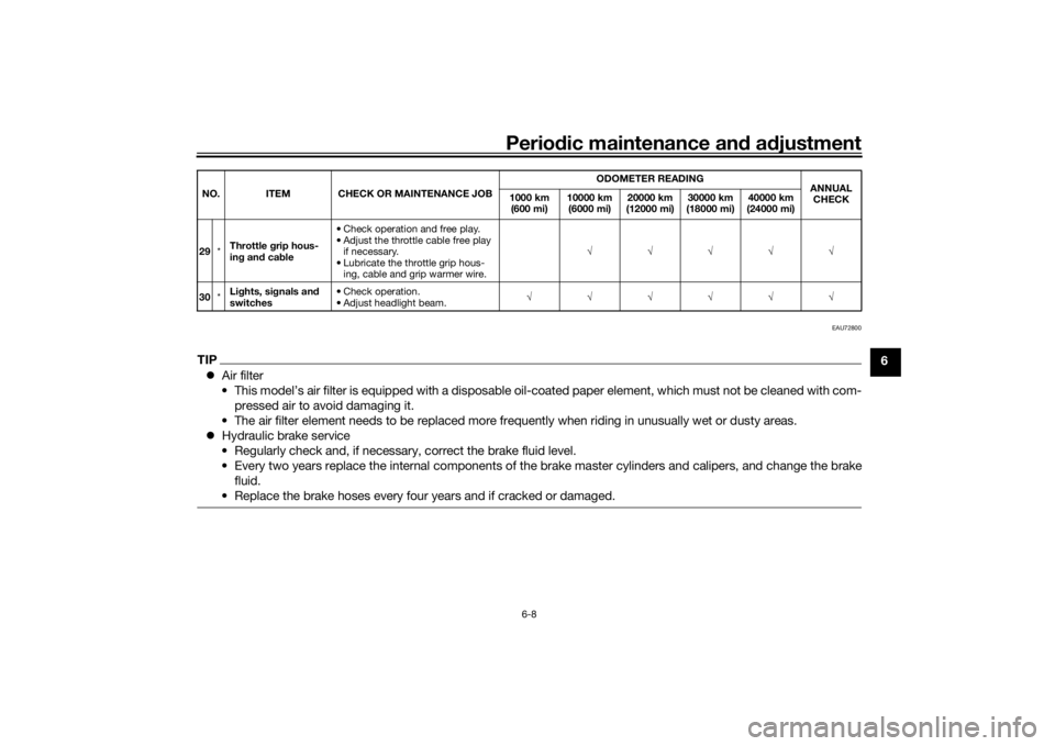
TIP Air filter
• This model’s air filter is equipped with a disposable oil-coated paper element, which must not be cleaned with com- pressed air to avoid damaging it.
• The air filter element needs to be replaced more frequently when riding in unusually wet or dusty areas.
Hydraulic brake service
• Regularly check and, if necessary, correct the brake fluid level.
• Every two years replace the internal components of the brake master cylinders and calipers, and change the brake fluid.
• Replace the brake hoses every four years and if cracked or damaged.29 *Throttle g
rip hous-
in g an d ca ble • Check operation and free play.
• Adjust the throttle cable free play
if necessary.
• Lubricate the throttle grip hous- ing, cable and grip warmer wire. √√√√√
30 *Li
ghts, si gnals an d
switches • Check operation.
• Adjust headlight beam.
√√√√√√
NO. ITEM CHECK OR MAINTENANCE JOB
ODOMETER READING
ANNUAL
CHECK
1000 km
(600 mi) 10000 km
(6000 mi) 20000 km
(12000 mi) 30000 km
(18000 mi) 40000 km
(24000 mi)
UB1JE1E0.book Page 8 Thursday, October 11, 2018 10:43 AM
Page 90 of 120
Periodic maintenance an d a djustment
6-21
6
EAU22393
Checkin g the front an d rear
b rake pa dsThe front and rear brake pads must be
checked for wear at the intervals spec-
ified in the periodic maintenance and
lubrication chart.
EAU36891
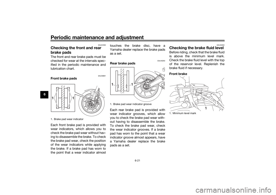
Front brake pa ds
Each front brake pad is provided with
wear indicators, which allows you to
check the brake pad wear without hav-
ing to disassemble the brake. To check
the brake pad wear, check the position
of the wear indicators while applying
the brake. If a brake pad has worn to
the point that a wear indicator almost touches the brake disc, have a
Yamaha dealer replace the brake pads as a set.
EAU46292
Rear brake pad s
Each rear brake pad is provided with
wear indicator grooves, which allow
you to check the brake pad wear with-
out having to disassemble the brake.
To check the brake pad wear, check
the wear indicator grooves. If a brake
pad has worn to the point that a wear
indicator groove almost appears, have
a Yamaha dealer replace the brake
pads as a set.
EAU40262
Checkin g the brake flui d levelBefore riding, check that the brake fluid
is above the minimum level mark.
Check the brake fluid level with the top
of the reservoir level. Replenish the
brake fluid if necessary.
Front brake
1. Brake pad wear indicator
1
1
1. Brake pad wear indicator groove
1
1
1. Minimum level mark
1
UB1JE1E0.book Page 21 Thursday, October 11, 2018 10:43 AM
Page 91 of 120
Periodic maintenance an d a djustment
6-22
6
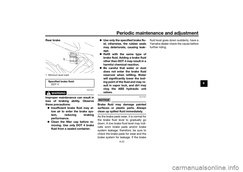
Rear
brake
WARNING
EWA16011
Improper maintenance can result in
loss of b raking a bility. O bserve
these precautions: Insufficient brake flui d may al-
low air to enter the brake sys-
tem, re ducin g brakin g
performance.
Clean the filler cap before re-
movin g. Use only DOT 4 brake
flui d from a seale d container.
Use only the specified b rake flu-
i d ; otherwise, the ru bber seals
may deteriorate, causin g leak-
a g e.
Refill with the same type of
brake flui d. A dding a brake fluid
other than DOT 4 may result in a
harmful chemical reaction.
Be careful that water or d ust
d oes not enter the brake flui d
reservoir when refillin g. Water
will si gnificantly lower the boil-
in g point of the flui d an d may re-
sult in vapor lock, an d d ir
t may
clo g the ABS hy draulic unit
valves.
NOTICE
ECA17641
Brake flui d may d amage painte d
surfaces or plastic parts. Always
clean up spilled fluid imme diately.As the brake pads wear, it is normal for
the brake fluid level to gradually go
down. A low brake fluid level may indi-
cate worn brake pads and/or brake
system leakage; therefore, be sure to
check the brake pads for wear and the
brake system for leakage. If the brake fluid level goes down suddenly, have a
Yamaha dealer check the cause before
further riding.
1. Minimum level markSpecifie
d b rake flui d:
DOT 4
1
UB1JE1E0.book Page 22 Thursday, October 11, 2018 10:43 AM
Page 92 of 120
Periodic maintenance an d a djustment
6-23
6
EAU22734
Chan gin g the brake flui dHave a Yamaha dealer change the
brake fluid every 2 years. In addition,
have the seals of the master cylinders
and brake calipers, as well as the brake
hoses replaced at the intervals listed
below or sooner if they are damaged or
leaking.
Brake seals: every 2 years
Brake hoses: every 4 years
EAU22762
Drive chain slackThe drive chain slack should be
checked before each ride and adjusted
if necessary.
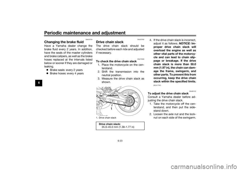
EAU73530
To check the drive chain slack
1. Place the motorcycle on the cen- terstand.
2. Shift the transmission into the neutral position.
3. Measure the drive chain slack as shown. 4. If the drive chain slack is incorrect,
adjust it as follows. NOTICE: Im-
proper drive chain slack will
overloa d the en gine as well as
other vital parts of the motorcy-
cle an d can lea d to chain slip-
pa ge or breakag e. If the drive
chain slack is more than 50.0
mm (1.97 in), the chain can dam-
a g e the frame, swin garm, an d
other parts. To prevent this from
occurrin g, keep the d rive chain
slack within the specified limits.
[ECA17791]
EAU63122
To adjust the drive chain slack
Consult a Yamaha dealer before ad-
justing the drive chain slack. 1. Take the motorcycle off the cen- terstand, and then put the side-
stand down.
2. Loosen the axle nut and the lock- nut on each side of the swingarm.
1. Drive chain slackDrive chain slack:35.0–45.0 mm (1.38–1.77 in)
1
UB1JE1E0.book Page 23 Thursday, October 11, 2018 10:43 AM