stop start YAMAHA TRACER 900 GT 2020 Owners Manual
[x] Cancel search | Manufacturer: YAMAHA, Model Year: 2020, Model line: TRACER 900 GT, Model: YAMAHA TRACER 900 GT 2020Pages: 120, PDF Size: 9.78 MB
Page 19 of 120
Instrument and control functions
3-4
3
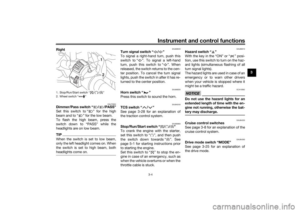
Ri
ght
EAU73924
Dimmer/Pass switch “ / /PASS”
Set this switch to “ ” for the high
beam and to “ ” for the low beam.
To flash the high beam, press the
switch down to “PASS” while the
headlights are on low beam.TIPWhen the switch is set to low beam,
only the left headlight comes on. When
the switch is set to high beam, both
headlights come on.
EAU66040
Turn si gnal switch “ / ”
To signal a right-hand turn, push this
switch to “ ”. To signal a left-hand
turn, push this switch to “ ”. When
released, the switch returns to the cen-
ter position. To cancel the turn signal
lights, push the switch in after it has re-
turned to the center position.
EAU66030
Horn switch “ ”
Press this switch to sound the horn.
EAU84240
TCS switch “ / ”
See page 3-28 for an explanation of
the traction control system.
EAU66060
Stop/Run/Start switch “ / / ”
To crank the engine with the starter,
set this switch to “ ”, and then push
the switch down towards “ ”. See
page 5-1 for starting instructions prior
to starting the engine.
Set this switch to “ ” to stop the en-
gine in case of an emergency, such as
when the vehicle overturns or when the
throttle cable is stuck.
EAU66010
Hazar d switch “ ”
With the key in the “ON” or “ ” posi-
tion, use this switch to turn on the haz-
ard lights (simultaneous flashing of all
turn signal lights).
The hazard lights are used in case of an
emergency or to warn other drivers
when your vehicle is stopped where it
might be a traffic hazard.NOTICE
ECA10062
Do not use the hazar d lig hts for an
exten ded len gth of time with the en-
g ine not runnin g, otherwise the bat-
tery may d ischarge.
EAU84250
Cruise control switches
See page 3-8 for an explanation of the
cruise control system.
EAU84260
Drive mo de switch “MODE”
See page 3-25 for an explanation of
the drive mode.
1. Stop/Run/Start switch “ / / ”
2. Wheel switch “ ”
1
2
UB1JE1E0.book Page 4 Thursday, October 11, 2018 10:43 AM
Page 22 of 120
Instrument and control functions
3-7
3
TIPWhen the vehicle is turned on, the light
should come on for a few seconds and
then go off. If the light does not come
on, or if the light remains on, have a
Yamaha dealer check vehicle.
EAU67432
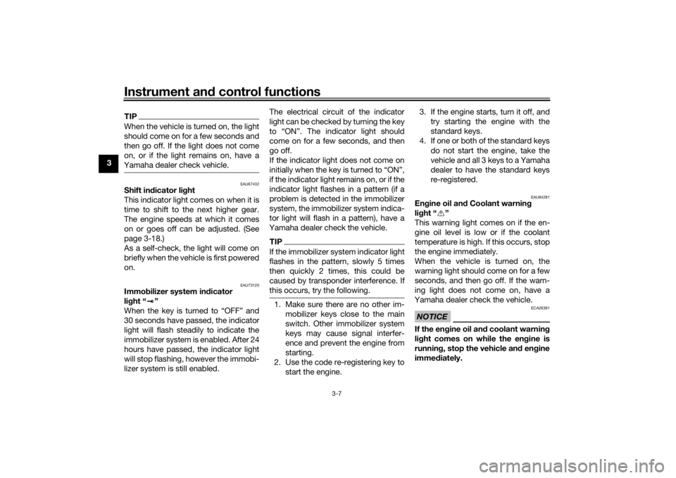
Shift in dicator li ght
This indicator light comes on when it is
time to shift to the next higher gear.
The engine speeds at which it comes
on or goes off can be adjusted. (See
page 3-18.)
As a self-check, the light will come on
briefly when the vehicle is first powered
on.
EAU73120
Immo bilizer system in dicator
li g ht “ ”
When the key is turned to “OFF” and
30 seconds have passed, the indicator
light will flash steadily to indicate the
immobilizer system is enabled. After 24
hours have passed, the indicator light
will stop flashing, however the immobi-
lizer system is still enabled. The electrical circuit of the indicator
light can be checked by turning the key
to “ON”. The indicator light should
come on for a few seconds, and then
go off.
If the indicator light does not come on
initially when the key is turned to “ON”,
if the indicator light remains on, or if the
indicator light flashes in a pattern (if a
problem is detected in the immobilizer
system, the immobilizer system indica-
tor light will flash in a pattern), have a
Yamaha dealer check the vehicle.
TIPIf the immobilizer system indicator light
flashes in the pattern, slowly 5 times
then quickly 2 times, this could be
caused by transponder interference. If
this occurs, try the following. 1. Make sure there are no other im- mobilizer keys close to the main
switch. Other immobilizer system
keys may cause signal interfer-
ence and prevent the engine from
starting.
2. Use the code re-registering key to start the engine. 3. If the engine starts, turn it off, and
try starting the engine with the
standard keys.
4. If one or both of the standard keys do not start the engine, take the
vehicle and all 3 keys to a Yamaha
dealer to have the standard keys
re-registered.
EAU84281
Engine oil an d Coolant warnin g
li g ht “ ”
This warning light comes on if the en-
gine oil level is low or if the coolant
temperature is high. If this occurs, stop
the engine immediately.
When the vehicle is turned on, the
warning light should come on for a few
seconds, and then go off. If the warn-
ing light does not come on, have a
Yamaha dealer check the vehicle.NOTICE
ECA26391
If the en gine oil an d coolant warnin g
li g ht comes on while the en gine is
running , stop the vehicle an d en gine
imme diately.
UB1JE1E0.book Page 7 Thursday, October 11, 2018 10:43 AM
Page 25 of 120

Instrument and control functions
3-10
3
Apply the front or rear brake.
Squeeze the clutch lever.
Use the shift pedal.
Push the power switch to turn off the
cruise control system. The “ ” indica-
tor light and the “SET” indicator light
will go off.
TIPTraveling speed decreases as soon as
the cruise control system is deactivat-
ed; unless the throttle grip is turned.Usin g the resume function
Push the “RES+” side of the cruise
control setting switch to reactivate the
cruise control system. The traveling
speed will return to the previously set
cruising speed. The “SET” indicator
light will come on.
WARNING
EWA16351
It is d angerous to use the resume
function when the previously set
cruisin g speed is too hi gh for current
con ditions.
TIPPushing the power switch while the
system is operating will turn the sys-
tem off completely and erase the previ-
ously set cruising speed. You will not
be able to use the resume function until
a new cruising speed has been set.Automatic deactivation of the cruisecontrol systemThe cruise control system for this mod-
el is electronically controlled and is
linked with the other control systems.
The cruise control system will auto-
matically become deactivated under
the following conditions:
The cruise control system is not
able to maintain the set cruising
speed.
Wheel slip or wheel spin is detect-
ed. (If the traction control system
has not been turned off, the trac-
tion control system will work.)
The start/engine stop switch is set
to the “ ” position.
The engine stalls.
The sidestand is lowered. When traveling with a set cruising
speed, if the cruise control system is
deactivated under the above condi-
tions, the “ ” indicator light will go off
and the “SET” indicator light will flash
for 4 seconds, and then go off.
When not traveling with a set cruising
speed, if the start/engine stop switch is
set to the “ ” position, the engine
stalls, or the sidestand is lowered, then
the “ ” indicator light will go off (the
“SET” indicator light will not flash).
If the cruise control system is automat-
ically deactivated, please stop and
confirm that your vehicle is in good op-
erating condition.
Before using the cruise control system
again, activate it using the power
switch.
TIPIn some cases, the cruise control sys-
tem may not be able to maintain the set
cruising speed when the vehicle is
traveling uphill or downhill.
When the vehicle is traveling up-
hill, the actual traveling speed may
become lower than the set cruis-
UB1JE1E0.book Page 10 Thursday, October 11, 2018 10:43 AM
Page 27 of 120
Instrument and control functions
3-12
3
WARNING
EWA18210
Stop the vehicle before makin g any
settin g chan ges. Chan gin g settin gs
while ri din g can distract the opera-
tor an d increase the risk of an acci-
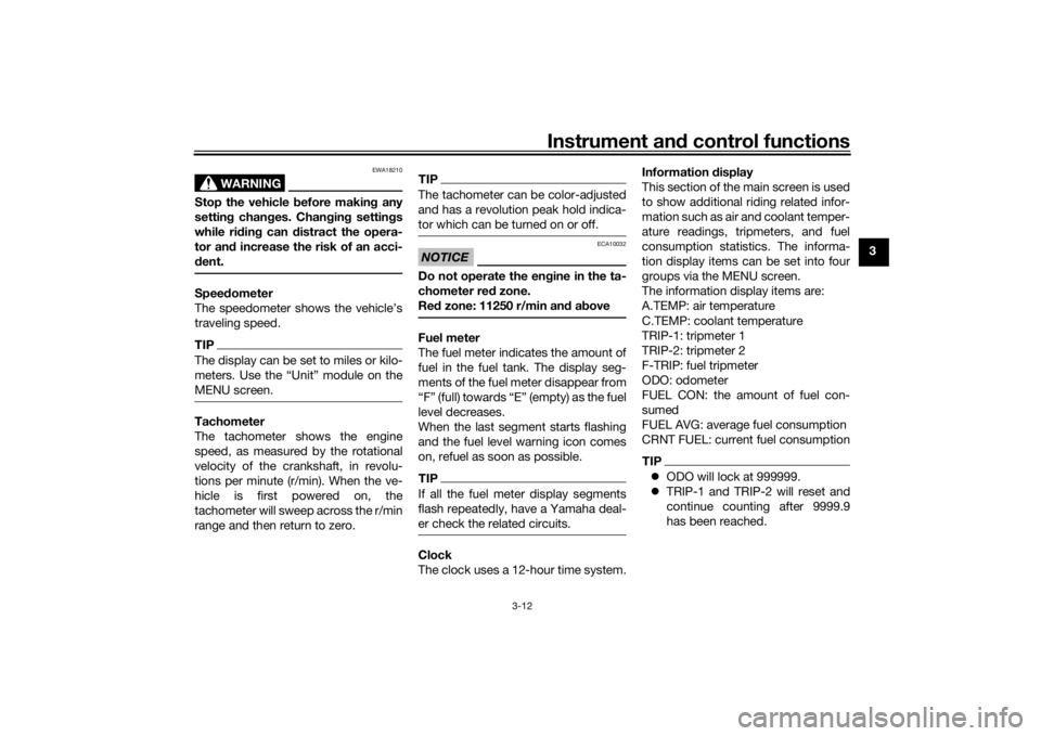
d ent.Spee dometer
The speedometer shows the vehicle’s
traveling speed.TIPThe display can be set to miles or kilo-
meters. Use the “Unit” module on the
MENU screen.Tachometer
The tachometer shows the engine
speed, as measured by the rotational
velocity of the crankshaft, in revolu-
tions per minute (r/min). When the ve-
hicle is first powered on, the
tachometer will sweep across the r/min
range and then return to zero.
TIPThe tachometer can be color-adjusted
and has a revolution peak hold indica-
tor which can be turned on or off.NOTICE
ECA10032
Do not operate the en gine in the ta-
chometer red zone.
Re d zone: 11250 r/min an d a boveFuel meter
The fuel meter indicates the amount of
fuel in the fuel tank. The display seg-
ments of the fuel meter disappear from
“F” (full) towards “E” (empty) as the fuel
level decreases.
When the last segment starts flashing
and the fuel level warning icon comes
on, refuel as soon as possible.TIPIf all the fuel meter display segments
flash repeatedly, have a Yamaha deal-
er check the related circuits.Clock
The clock uses a 12-hour time system. Information
display
This section of the main screen is used
to show additional riding related infor-
mation such as air and coolant temper-
ature readings, tripmeters, and fuel
consumption statistics. The informa-
tion display items can be set into four
groups via the MENU screen.
The information display items are:
A.TEMP: air temperature
C.TEMP: coolant temperature
TRIP-1: tripmeter 1
TRIP-2: tripmeter 2
F-TRIP: fuel tripmeter
ODO: odometer
FUEL CON: the amount of fuel con-
sumed
FUEL AVG: average fuel consumption
CRNT FUEL: current fuel consumption
TIP ODO will lock at 999999.
TRIP-1 and TRIP-2 will reset and
continue counting after 9999.9
has been reached.
UB1JE1E0.book Page 12 Thursday, October 11, 2018 10:43 AM
Page 33 of 120
Instrument and control functions
3-18
3
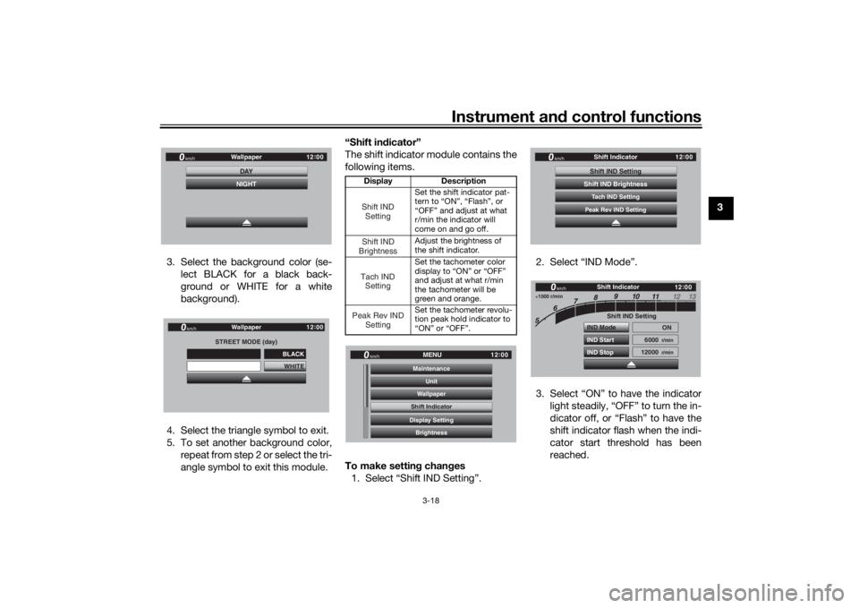
3. Select the background color (se- lect BLACK for a black back-
ground or WHITE for a white
background).
4. Select the triangle symbol to exit.
5. To set another background color, repeat from step 2 or select the tri-
angle symbol to exit this module. “Shift in
dicator”
The shift indicator module contains the
following items.
To make settin g chan ges
1. Select “Shift IND Setting”. 2. Select “IND Mode”.
3. Select “ON” to have the indicator
light steadily, “OFF” to turn the in-
dicator off, or “Flash” to have the
shift indicator flash when the indi-
cator start threshold has been
reached.
12:
00
Wallpaper
km/h
DAYNIGHT
STREET MODE (day)
WHITE
Wallpaper
km/h
GPS
12 :
00
BLACK
Display Description
Set the shift indicator pat-
tern to “ON”, “Flash”, or
“OFF” and adjust at what
r/min the indicator will
come on and go off.
Adjust the brightness of
the shift indicator.
Set the tachometer color
display to “ON” or “OFF”
and adjust at what r/min
the tachometer will be
green and orange.
Set the tachometer revolu-
tion peak hold indicator to
“ON” or “OFF”.Shift IND SettingShift IND
BrightnessTach IND SettingPeak Rev IND Setting
12:
00
MENU
km/h
BrightnessDisplay SettingShift IndicatorWallpaperUnit
MaintenanceShift Indicator
12 :
00
Shift Indicator
km/h
Tach IND SettingShift IND SettingPeak Rev IND SettingShift IND Brightness
1000 r/min
12 :
00
Shift IND Setting
IND Mode
IND Start
IND Stop ON
6000
r/min
12000
r/min
km/h
Shift Indicator
UB1JE1E0.book Page 18 Thursday, October 11, 2018 10:43 AM
Page 34 of 120
Instrument and control functions
3-19
3
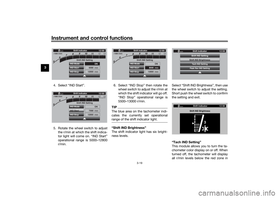
4. Select “IND Start”.
5. Rotate the wheel switch to adjustthe r/min at which the shift indica-
tor light will come on. “IND Start”
operational range is 5000–12800
r/min. 6. Select “IND Stop” then rotate the
wheel switch to adjust the r/min at
which the shift indicator will go off.
“IND Stop” operational range is
5500–13000 r/min.
TIPThe blue area on the tachometer indi-
cates the currently set operational
range of the shift indicator light.“Shift IND Bri ghtness”
The shift indicator light has six bright-
ness levels. Select “Shift IND Brightness”, then use
the wheel switch to adjust the setting.
Short push the wheel switch to confirm
the setting and exit.
“Tach IND Settin
g”
This module allows you to turn the ta-
chometer color display on or off. When
turned off, the tachometer will display
all r/min levels below the red zone in
1000 r/min
12 :
00
Shift IND Setting
IND Mode
IND Start
IND Stop ON
6000
r/min
12000
r/min
km/h
Shift Indicator
1000 r/min
12 :
00
Shift IND Setting
IND Mode
IND Start
IND Stop ON
7000
r/min
12000
r/min
km/h
Shift Indicator
1000 r/min
12 :
00
Shift IND Setting
IND Mode
IND Start
IND Stop ON
8000
r/min
13000
r/min
km/h
Shift Indicator
12 :
00
Shift Indicator
km/h
Tach IND SettingShift IND SettingPeak Rev IND SettingShift IND Brightness
12 :
00
Shift Indicator
km/h
Shift IND Bri ghtness
3
UB1JE1E0.book Page 19 Thursday, October 11, 2018 10:43 AM
Page 60 of 120

Instrument and control functions
3-45
3
EAU57952
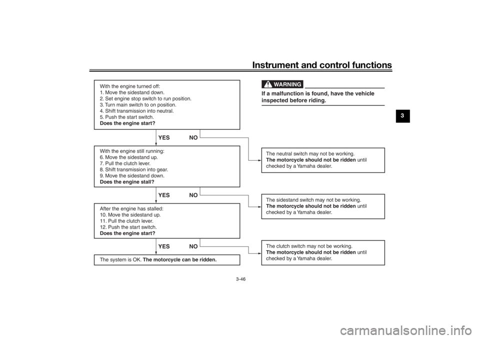
Ig nition circuit cut-off systemThis system prevents in-gear engine
starts unless the clutch lever is pulled
and the sidestand is up. Also, it will
stop the running engine should the
sidestand be lowered while the trans-
mission is in gear.
Periodically check this system via the
following procedure.TIP This check is most reliable if per-
formed with a warmed-up engine.
See pages 3-2 and 3-3 for switch
operation information.
UB1JE1E0.book Page 45 Thursday, October 11, 2018 10:43 AM
Page 61 of 120
Instrument and control functions
3-46
3
With the engine turned off:
1. Move the sidestand down.
2. Set engine stop switch to run position.
3. Turn main switch to on position.
4. Shift transmission into neutral.
5. Push the start switch.
Does the engine start?
With the engine still running:
6. Move the sidestand up.
7. Pull the clutch lever.
8. Shift transmission into gear.
9. Move the sidestand down.
Does the engine stall?
After the engine has stalled:
10. Move the sidestand up.
11. Pull the clutch lever.
12. Push the start switch.
Does the engine start?
The system is OK. The motorcycle can be ridden.
YES NO YES NO YES NO
The neutral switch may not be working.
The motorcycle should not be ridden until
checked by a Yamaha dealer.
The clutch switch may not be working.
The motorcycle should not be ridden until
checked by a Yamaha dealer.The sidestand switch may not be working.
The motorcycle should not be ridden until
checked by a Yamaha dealer.If a malfunction is found, have the vehicle
inspected before riding.
WARNING
UB1JE1E0.book Page 46 Thursday, October 11, 2018 10:43 AM
Page 65 of 120

Operation and important ri din g points
5-1
5
EAU15952
Read the Owner’s Manual carefully to
become familiar with all controls. If
there is a control or function you do not
understand, ask your Yamaha dealer.
WARNING
EWA10272
Failure to familiarize yourself with
the controls can lead to loss of con-
trol, which coul d cause an acci dent
or injury.
EAUM3632
TIPThis model is equipped with: a lean angle sensor. This sensor
stops the engine in case of a vehi-
cle turnover. If this happens, the
engine trouble warning light will
come on, but this is not a malfunc-
tion. Turn the vehicle power off
and then back on again to cancel
the warning light. Failing to do so
will prevent the engine from start-
ing even though the engine will
crank when pushing the start
switch.
an engine auto-stop system. The
engine stops automatically if left
idling for 20 minutes. If the engine
stops, simply push the start
switch to restart the engine.
EAU84361
Startin g the en gineUnder normal conditions, shift the
transmission into neutral before start-
ing the engine. To start the engine with
the transmission in gear, the sidestand
must be up and the clutch lever pulled.
To start the engine1. Turn the main switch to “ON”, and
set the engine stop switch to “ ”.
2. Confirm the following lights per- form a circuit check. Engine trouble warning light
ABS warning light
Traction control system indi-
cator light
Cruise control indicator lights
Shift indicator light
Engine oil and Coolant warn-
ing light
Immobilizer system indicator
lightTIP The ABS warning light should go
off after reaching a speed of 10
km/h (6 mi/h) or higher.
UB1JE1E0.book Page 1 Thursday, October 11, 2018 10:43 AM
Page 67 of 120
Operation and important ri din g points
5-3
5
2. Shift the transmission into first
gear. The neutral indicator light
should go out.
3. Open the throttle gradually, and at the same time, release the clutch
lever slowly.
4. After starting out, close the throt- tle, and at the same time, quickly
pull the clutch lever in.
5. Shift the transmission into second gear. (Make sure not to shift the
transmission into the neutral posi-
tion.)
6. Open the throttle part way and gradually release the clutch lever.
7. Follow the same procedure when shifting to the next higher gear.
EAU85380
To decelerate
1. Release the throttle and apply both the front and the rear brakes
smoothly to slow the motorcycle.
2. As the vehicle decelerates, shift to a lower gear. 3. When the engine is about to stall
or runs roughly, pull the clutch le-
ver in, use the brakes to slow the
motorcycle, and continue to
downshift as necessary.
4. Once the motorcycle has stopped, the transmission can be
shifted into the neutral position.
The neutral indicator light should
come on and then the clutch lever
can be released.
WARNING
EWA17380
Improper brakin g can cause
loss of control or traction. Al-
ways use b oth brakes an d apply
them smoothly.
Make sure that the motorcycle
and the en gine have sufficiently
slowe d b efore shiftin g to a low-
er gear. En gag in g a lower gear
when the vehicle or en gine
spee d is too hi gh coul d make
the rear wheel lose traction or
the en gine to over-rev. This
coul d cause loss of control, an acci
dent an d injury. It coul d also
cause en gine or d rive train dam-
a g e.
UB1JE1E0.book Page 3 Thursday, October 11, 2018 10:43 AM