torque YAMAHA TT-R110E 2020 Owners Manual
[x] Cancel search | Manufacturer: YAMAHA, Model Year: 2020, Model line: TT-R110E, Model: YAMAHA TT-R110E 2020Pages: 88, PDF Size: 2.26 MB
Page 44 of 88

Periodic maintenance an d a djustment
7-2
7
EAU17303
Emission controls not only function to
ensure cleaner air, but are also vital to
proper engine operation and maximum
performance. In the following periodic
maintenance charts, the services relat-
ed to emissions control are grouped
separately. These services require
specialized data, knowledge, and
equipment. Maintenance, replace-
ment, or repair of the emission control
devices and systems may be per-
formed by any repair establishment or
individual that is certified (if applicable).
Yamaha dealers are trained and equipped to perform these particular
services.
EAU17312
Owner’s tool kit
The service information included in this
manual and the tools provided in the
owner’s tool kit are intended to assist
you in the performance of preventive
maintenance and minor repairs. How-
ever, additional tools such as a torque
wrench may be necessary to perform
certain maintenance work correctly.
TIP
If you do not have the tools or experi-
ence required for a particular job, have
a Yamaha dealer perform it for you.
UB5185E0.book Page 2 Monday, June 17, 2019 9:04 AM
Page 50 of 88
Periodic maintenance an d a djustment
7-8
7 To install the spark plu
g
1. Clean the surface of the spark plug gasket and its mating surfa-
ce, and then wipe off any grime
from the spark plug threads.
2. Install the spark plug with the spark plug wrench, and then tight-
en it to the specified torque.
TIP
If a torque wrench is not available
when installing a spark plug, a good
estimate of the correct torque is 1/4–
1/2 turn past finger tight. However, the
spark plug should be tightened to the
specified torque as soon as possible.
3. Install the spark plug cap.
EAU39848
Engine oil
The engine oil level should be checked
before each ride. In addition, the oil
must be changed at the intervals spec-
ified in the periodic maintenance and
lubrication chart.
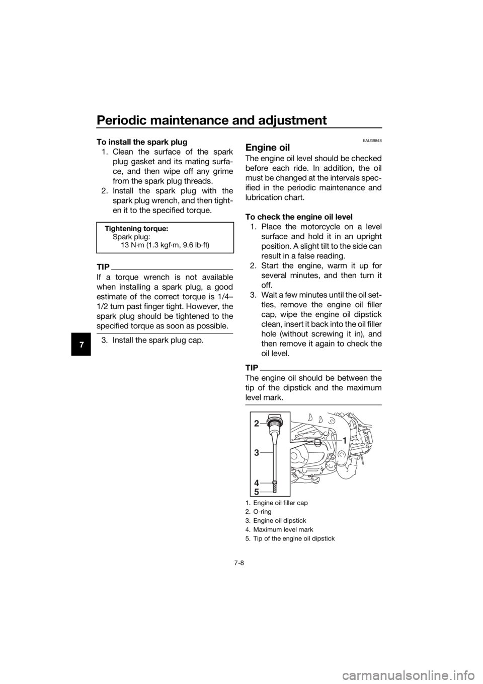
To check the en gine oil level
1. Place the motorcycle on a level surface and hold it in an upright
position. A slight tilt to the side can
result in a false reading.
2. Start the engine, warm it up for several minutes, and then turn it
off.
3. Wait a few minutes until the oil set- tles, remove the engine oil filler
cap, wipe the engine oil dipstick
clean, insert it back into the oil filler
hole (without screwing it in), and
then remove it again to check the
oil level.
TIP
The engine oil should be between the
tip of the dipstick and the maximum
level mark.
Tightenin g torque:
Spark plug: 13 N·m (1.3 kgf·m, 9.6 lb·ft)
1. Engine oil filler cap
2. O-ring
3. Engine oil dipstick
4. Maximum level mark
5. Tip of the engine oil dipstick
1
4
5
3
2
UB5185E0.book Page 8 Monday, June 17, 2019 9:04 AM
Page 51 of 88
Periodic maintenance an d a djustment
7-9
7
4. If the engine oil is not between the
tip of the dipstick and the maxi-
mum level mark, add sufficient oil
of the recommended type to raise
it to the correct level.
5. Check the O-ring for damage, and replace it if necessary.
6. Insert the dipstick into the oil filler hole, and then tighten the oil filler
cap.
To chan ge the en gine oil
1. Start the engine, warm it up for several minutes, and then turn it
off.
2. Place an oil pan under the engine to collect the used oil.
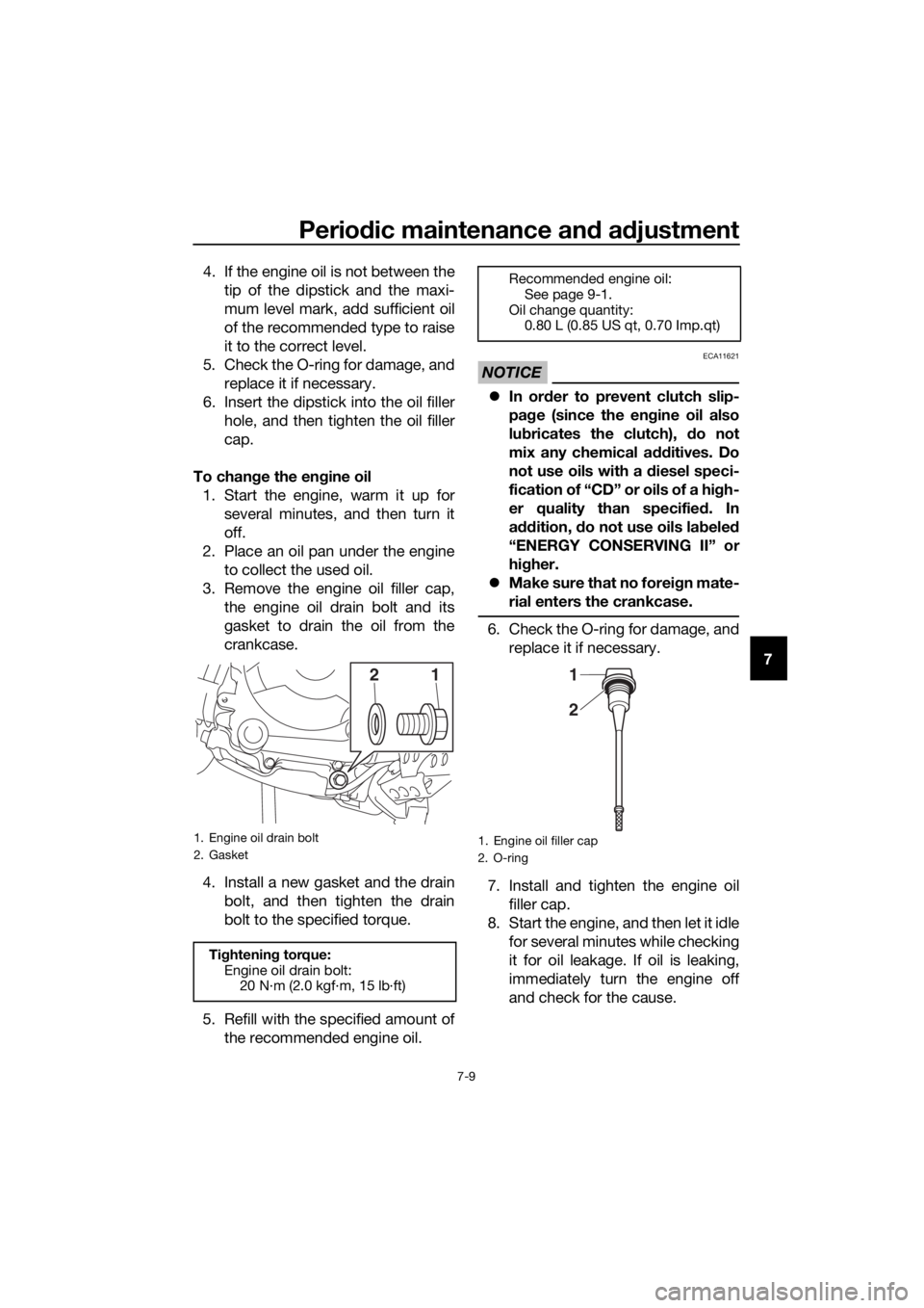
3. Remove the engine oil filler cap, the engine oil drain bolt and its
gasket to drain the oil from the
crankcase.
4. Install a new gasket and the drain bolt, and then tighten the drain
bolt to the specified torque.
5. Refill with the specified amount of the recommended engine oil.
NOTICE
ECA11621
In or der to prevent clutch slip-
pa ge (since the en gine oil also
lu bricates the clutch), do not
mix any chemical additives. Do
not use oils with a diesel speci-
fication of “CD” or oils of a hi gh-
er quality than specified . In
a dd ition, do not use oils la bele d
“ENERGY CONSERVING II” or
hi gher.
Make sure that no forei gn mate-
rial enters the crankcase.
6. Check the O-ring for damage, and replace it if necessary.
7. Install and tighten the engine oil filler cap.
8. Start the engine, and then let it idle for several minutes while checking
it for oil leakage. If oil is leaking,
immediately turn the engine off
and check for the cause.
1. Engine oil drain bolt
2. Gasket
Tightening torque:
Engine oil drain bolt: 20 N·m (2.0 kgf·m, 15 lb·ft)
12
Recommended engine oil:
See page 9-1.
Oil change quantity: 0.80 L (0.85 US qt, 0.70 Imp.qt)
1. Engine oil filler cap
2. O-ring
2
1
UB5185E0.book Page 9 Monday, June 17, 2019 9:04 AM
Page 55 of 88
Periodic maintenance an d a djustment
7-13
7
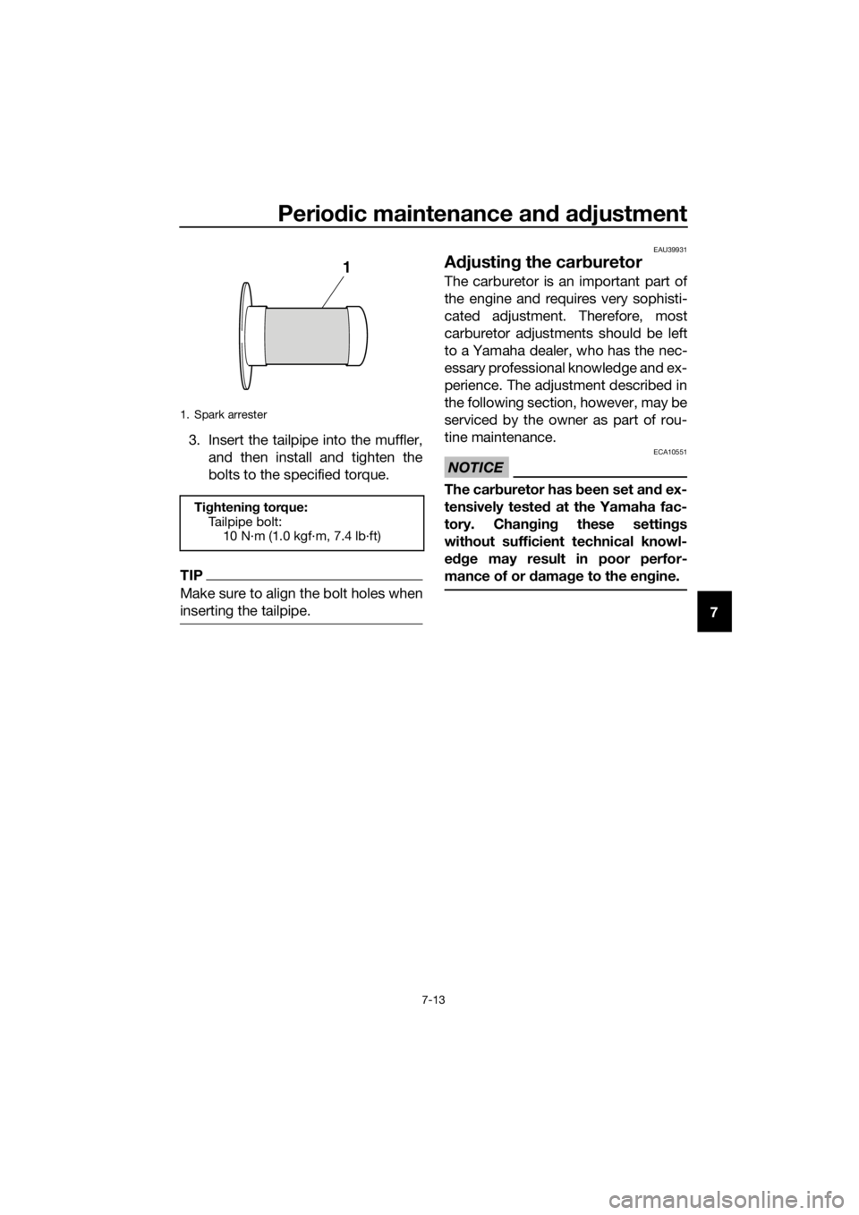
3. Insert the tailpipe into the muffler,
and then install and tighten the
bolts to the specified torque.
TIP
Make sure to align the bolt holes when
inserting the tailpipe.
EAU39931
Adjustin g the car buretor
The carburetor is an important part of
the engine and requires very sophisti-
cated adjustment. Therefore, most
carburetor adjustments should be left
to a Yamaha dealer, who has the nec-
essary professional knowledge and ex-
perience. The adjustment described in
the following section, however, may be
serviced by the owner as part of rou-
tine maintenance.
NOTICE
ECA10551
The car buretor has b een set and ex-
tensively teste d at the Yamaha fac-
tory. Chan gin g these settin gs
without sufficient technical knowl-
e dge may result in poor perfor-
mance of or d amage to the en gine.
1. Spark arrester
Ti ghtening torque:
Tailpipe bolt: 10 N·m (1.0 kgf·m, 7.4 lb·ft)
1
UB5185E0.book Page 13 Monday, June 17, 2019 9:04 AM
Page 60 of 88
Periodic maintenance an d a djustment
7-18
7
EAU44664
A djustin g the clutch free play
The clutch free play must be checked
and, if necessary, adjusted as follows
at the intervals specified in the periodic
maintenance and lubrication chart.
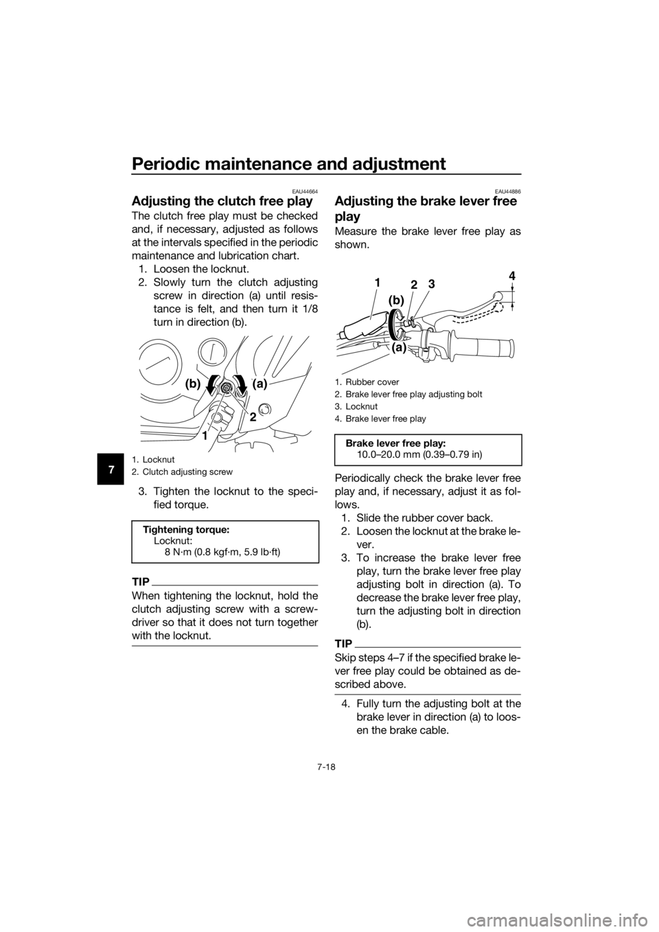
1. Loosen the locknut.
2. Slowly turn the clutch adjusting screw in direction (a) until resis-
tance is felt, and then turn it 1/8
turn in direction (b).
3. Tighten the locknut to the speci- fied torque.
TIP
When tightening the locknut, hold the
clutch adjusting screw with a screw-
driver so that it does not turn together
with the locknut.
EAU44886
Adjustin g the brake lever free
play
Measure the brake lever free play as
shown.
Periodically check the brake lever free
play and, if necessary, adjust it as fol-
lows.
1. Slide the rubber cover back.
2. Loosen the locknut at the brake le- ver.
3. To increase the brake lever free play, turn the brake lever free play
adjusting bolt in direction (a). To
decrease the brake lever free play,
turn the adjusting bolt in direction
(b).
TIP
Skip steps 4–7 if the specified brake le-
ver free play could be obtained as de-
scribed above.
4. Fully turn the adjusting bolt at thebrake lever in direction (a) to loos-
en the brake cable.
1. Locknut
2. Clutch adjusting screw
Tightenin g torque:
Locknut:
8 N·m (0.8 kgf·m, 5.9 lb·ft)
1 2
(a)(b)1. Rubber cover
2. Brake lever free play adjusting bolt
3. Locknut
4. Brake lever free play
Brake lever free play:
10.0–20.0 mm (0.39–0.79 in)
3
21
(b)
(a) 4
UB5185E0.book Page 18 Monday, June 17, 2019 9:04 AM
Page 64 of 88
Periodic maintenance an d a djustment
7-22
7
TIP
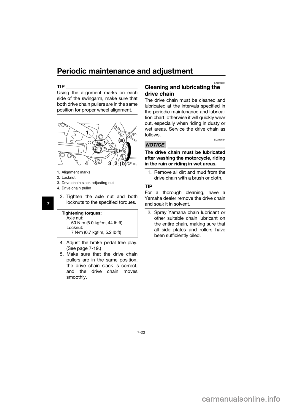
Using the alignment marks on each
side of the swingarm, make sure that
both drive chain pullers are in the same
position for proper wheel alignment.
3. Tighten the axle nut and both
locknuts to the specified torques.
4. Adjust the brake pedal free play. (See page 7-19.)
5. Make sure that the drive chain pullers are in the same position,
the drive chain slack is correct,
and the drive chain moves
smoothly.
EAU23018
Cleanin g an d lu bricatin g the
d rive chain
The drive chain must be cleaned and
lubricated at the intervals specified in
the periodic maintenance and lubrica-
tion chart, otherwise it will quickly wear
out, especially when riding in dusty or
wet areas. Service the drive chain as
follows.
NOTICE
ECA10584
The drive chain must be lu bricate d
after washin g the motorcycle, ri din g
in the rain or ri din g in wet areas.
1. Remove all dirt and mud from the
drive chain with a brush or cloth.
TIP
For a thorough cleaning, have a
Yamaha dealer remove the drive chain and soak it in solvent.
2. Spray Yamaha chain lubricant or other suitable chain lubricant on
the entire chain, making sure that
all side plates and rollers have
been sufficiently oiled.
1. Alignment marks
2. Locknut
3. Drive chain slack adjusting nut
4. Drive chain puller
Tightenin g torques:
Axle nut:
60 N·m (6.0 kgf·m, 44 lb·ft)
Locknut: 7 N·m (0.7 kgf·m, 5.2 lb·ft)
(a)
(b)
432 1
UB5185E0.book Page 22 Monday, June 17, 2019 9:04 AM
Page 73 of 88
Periodic maintenance an d a djustment
7-31
7
3. Insert the wheel axle from the right
side, and then install the washer
and the axle nut.
4. Lower the front wheel so that it is on the ground, and then put the
sidestand down.
5. Tighten the axle nut to the speci- fied torque.
6. Adjust the brake lever free play. (See page 7-18.)
7. While applying the front brake, push down hard on the handlebar
several times to check for proper
fork operation.
EAU25081
Rear wheel
EAU56801
To remove the rear wheel
WARNING
EWA10822
To avoi d injury, securely support the
vehicle so there is no dan ger of it
fallin g over.
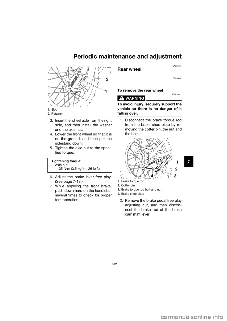
1. Disconnect the brake torque rod
from the brake shoe plate by re-
moving the cotter pin, the nut and
the bolt.
2. Remove the brake pedal free play adjusting nut, and then discon-
nect the brake rod at the brake
camshaft lever.
1. Slot
2. Retainer
Tightening torque:
Axle nut: 35 N·m (3.5 kgf·m, 26 lb·ft)
2
1
1. Brake torque rod
2. Cotter pin
3. Brake torque rod bolt and nut
4. Brake shoe plate
UB5185E0.book Page 31 Monday, June 17, 2019 9:04 AM
Page 74 of 88
Periodic maintenance an d a djustment
7-32
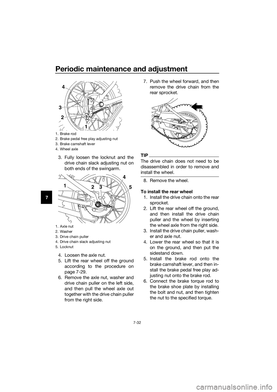
7 3. Fully loosen the locknut and the
drive chain slack adjusting nut on
both ends of the swingarm.
4. Loosen the axle nut.
5. Lift the rear wheel off the ground according to the procedure on
page 7-29.
6. Remove the axle nut, washer and drive chain puller on the left side,
and then pull the wheel axle out
together with the drive chain puller
from the right side. 7. Push the wheel forward, and then
remove the drive chain from the
rear sprocket.
TIP
The drive chain does not need to be
disassembled in order to remove and
install the wheel.
8. Remove the wheel.
To install the rear wheel 1. Install the drive chain onto the rear sprocket.
2. Lift the rear wheel off the ground, and then install the drive chain
puller and the wheel by inserting
the wheel axle from the right side.
3. Install the drive chain puller, wash- er and axle nut.
4. Lower the rear wheel so that it is on the ground, and then put the
sidestand down.
5. Install the brake rod onto the brake camshaft lever, and then in-
stall the brake pedal free play ad-
justing nut onto the brake rod.
6. Connect the brake torque rod to the brake shoe plate by installing
the bolt and nut, and then tighten
the nut to the specified torque.
1. Brake rod
2. Brake pedal free play adjusting nut
3. Brake camshaft lever
4. Wheel axle
1. Axle nut
2. Washer
3. Drive chain puller
4. Drive chain slack adjusting nut
5. Locknut
1 23 5
4
UB5185E0.book Page 32 Monday, June 17, 2019 9:04 AM
Page 75 of 88
Periodic maintenance an d a djustment
7-33
7
7. Insert a new cotter pin.
8. Adjust the drive chain slack. (See
page 7-21.)
9. Tighten the axle nut and both locknuts to the specified torque.
10. Adjust the brake pedal free play. (See page 7-19.)
EAU25853
Trou bleshootin g
Although Yamaha motorcycles receive
a thorough inspection before shipment
from the factory, trouble may occur
during operation. Any problem in the
fuel, compression, or ignition systems,
for example, can cause poor starting
and loss of power.
The following troubleshooting chart
represents a quick and easy procedure
for checking these vital systems your-
self. However, should your motorcycle
require any repair, take it to a Yamaha
dealer, whose skilled technicians have
the necessary tools, experience, and
know-how to service the motorcycle
properly.
Use only genuine Yamaha replace-
ment parts. Imitation parts may look
like Yamaha parts, but they are often
inferior, have a shorter service life and
can lead to expensive repair bills.
WARNING
EWA15142
When checkin g the fuel system, do
not smoke, an d make sure there are
no open flames or sparks in the ar-
ea, inclu din g pilot li ghts from water
heaters or furnaces. Gasoline or
g asoline vapors can i gnite or ex-
plo de, causin g severe injury or prop-
erty damag e.
Tightening torque:
Brake torque rod nut: 26 N·m (2.6 kgf·m, 19 lb·ft)
Ti ghtening torque:
Axle nut: 60 N·m (6.0 kgf·m, 44 lb·ft)
Locknut: 7 N·m (0.7 kgf·m, 5.2 lb·ft)
UB5185E0.book Page 33 Monday, June 17, 2019 9:04 AM