seat adjustment YAMAHA TTR110 2010 Owners Manual
[x] Cancel search | Manufacturer: YAMAHA, Model Year: 2010, Model line: TTR110, Model: YAMAHA TTR110 2010Pages: 84, PDF Size: 2.59 MB
Page 9 of 84

TABLE OF CONTENTS
LOCATION OF IMPORTANT
LABELS ............................................1-1
SAFETY INFORMATION .................. 2-1
DESCRIPTION .................................. 3-1
Left view .......................................... 3-1
Right view ........................................ 3-2
Controls and instruments ................3-3
INSTRUMENT AND CONTROL
FUNCTIONS....................................... 4-1
Main switch ..................................... 4-1
Handlebar switches ........................ 4-1
Shift pedal ......................................4-2
Brake lever ..................................... 4-2
Brake pedal .................................... 4-3
Fuel tank cap .................................. 4-3
Fuel ................................................ 4-3
Fuel tank breather hose ................. 4-5
Fuel cock ........................................ 4-5
Starter (choke) lever ....................... 4-6
Kickstarter ......................................4-7
Seat ................................................ 4-7
Shock absorber assembly .............. 4-8
Sidestand ....................................... 4-8
Starting circuit cut-off system ......... 4-8FOR YOUR SAFETY –
PRE-OPERATION CHECKS............. 5-1
OPERATION AND IMPORTANT
RIDING POINTS................................ 6-1
Starting and warming up
a cold engine .............................. 6-1
Starting a warm engine .................. 6-2
Shifting ........................................... 6-2
Engine break-in .............................. 6-3
Parking ........................................... 6-4
PERIODIC MAINTENANCE AND
ADJUSTMENT................................... 7-1
Owner’s tool kit .............................. 7-2
Periodic maintenance chart for
the emission control system ....... 7-3
General maintenance and
lubrication chart .......................... 7-4
Removing and installing panels ..... 7-7
Checking the spark plug ................ 7-8
Engine oil ....................................... 7-9
Cleaning the air filter element ...... 7-11
Cleaning the spark arrester ......... 7-13
Adjusting the carburetor ............... 7-14
Adjusting the engine idling
speed ........................................ 7-14
Checking the throttle cable
free play .................................... 7-15
Valve clearance ........................... 7-15
Tires ............................................. 7-15Spoke wheels ............................... 7-17
Adjusting the clutch free play ....... 7-17
Adjusting the brake lever free
play ........................................... 7-18
Adjusting the brake pedal free
play ........................................... 7-19
Checking the shift pedal ............... 7-20
Checking the front and
rear brake shoes ....................... 7-20
Drive chain slack .......................... 7-21
Cleaning and lubricating
the drive chain .......................... 7-22
Checking and lubricating
the cables ................................. 7-23
Checking and lubricating
the throttle grip and cable ......... 7-23
Checking and lubricating
the brake lever .......................... 7-23
Checking and lubricating
the brake pedal ......................... 7-24
Checking and lubricating
the sidestand ............................ 7-24
Lubricating the swingarm pivots ... 7-24
Checking the front fork ................. 7-25
Checking the steering .................. 7-25
Checking the wheel bearings ....... 7-26
Battery .......................................... 7-26
Replacing the fuse ....................... 7-27
Supporting the motorcycle ........... 7-28
Front wheel .................................. 7-29
Rear wheel ................................... 7-30
U5B682E0.book Page 1 Tuesday, June 9, 2009 2:04 PM
Page 47 of 84

PERIODIC MAINTENANCE AND ADJUSTMENT
7-7
7
EAU18771
Removing and installing pan-
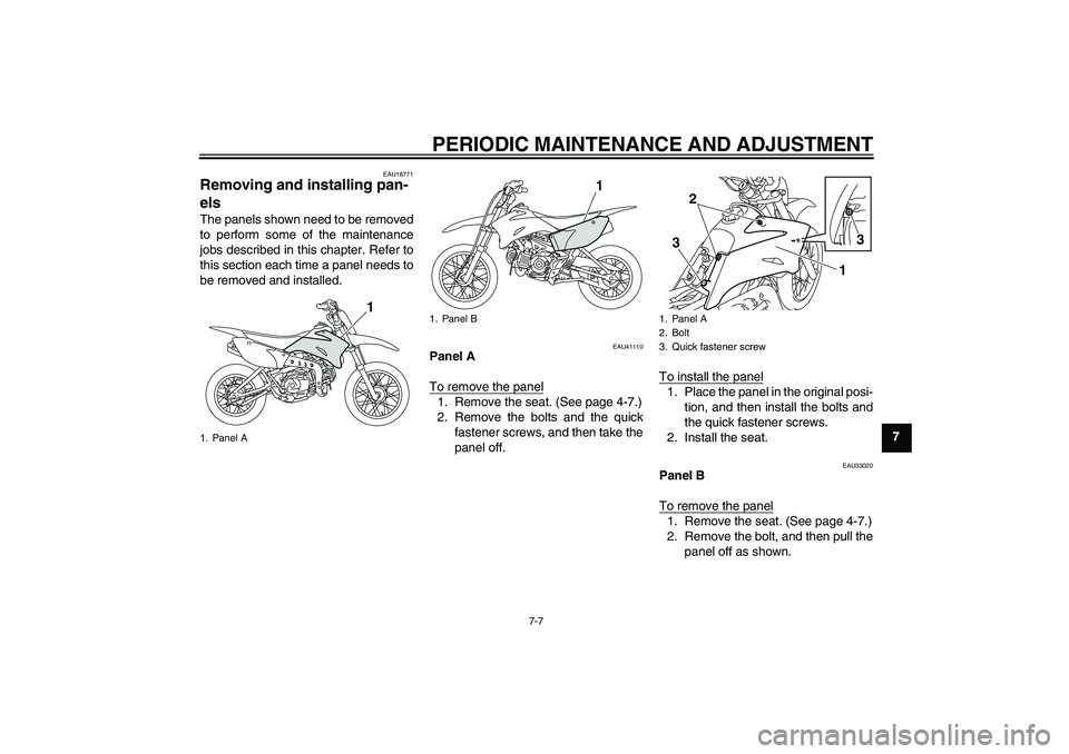
els The panels shown need to be removed
to perform some of the maintenance
jobs described in this chapter. Refer to
this section each time a panel needs to
be removed and installed.
EAU41110
Panel A
To remove the panel1. Remove the seat. (See page 4-7.)
2. Remove the bolts and the quick
fastener screws, and then take the
panel off.To install the panel
1. Place the panel in the original posi-
tion, and then install the bolts and
the quick fastener screws.
2. Install the seat.
EAU33020
Panel B
To remove the panel1. Remove the seat. (See page 4-7.)
2. Remove the bolt, and then pull the
panel off as shown.
1. Panel A
1
1. Panel B
1
1. Panel A
2. Bolt
3. Quick fastener screw
3
1 2
3
U5B682E0.book Page 7 Tuesday, June 9, 2009 2:04 PM
Page 48 of 84

PERIODIC MAINTENANCE AND ADJUSTMENT
7-8
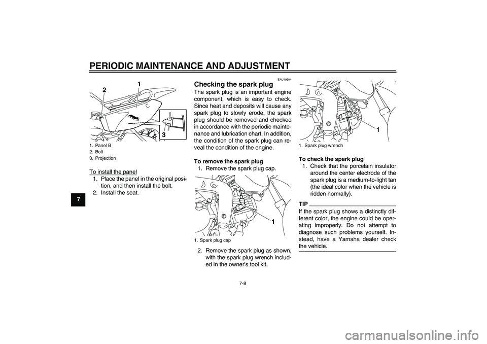
7To install the panel
1. Place the panel in the original posi-
tion, and then install the bolt.
2. Install the seat.
EAU19604
Checking the spark plug The spark plug is an important engine
component, which is easy to check.
Since heat and deposits will cause any
spark plug to slowly erode, the spark
plug should be removed and checked
in accordance with the periodic mainte-
nance and lubrication chart. In addition,
the condition of the spark plug can re-
veal the condition of the engine.
To remove the spark plug
1. Remove the spark plug cap.
2. Remove the spark plug as shown,
with the spark plug wrench includ-
ed in the owner’s tool kit.To check the spark plug
1. Check that the porcelain insulator
around the center electrode of the
spark plug is a medium-to-light tan
(the ideal color when the vehicle is
ridden normally).
TIPIf the spark plug shows a distinctly dif-
ferent color, the engine could be oper-
ating improperly. Do not attempt to
diagnose such problems yourself. In-
stead, have a Yamaha dealer check
the vehicle.
1. Panel B
2. Bolt
3. Projection
3
1
2
1. Spark plug cap
1
1. Spark plug wrench
1
U5B682E0.book Page 8 Tuesday, June 9, 2009 2:04 PM
Page 51 of 84

PERIODIC MAINTENANCE AND ADJUSTMENT
7-11
7
EAU41636
Cleaning the air filter element The air filter element should be cleaned
or replaced at the intervals specified in
the periodic maintenance and lubrica-
tion chart. Clean or, if necessary, re-
place the air filter element more
frequently if you are riding in unusually
wet or dusty areas.
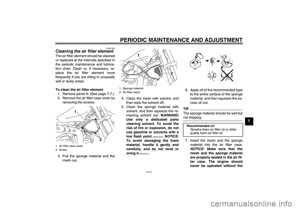
To clean the air filter element
1. Remove panel A. (See page 7-7.)
2. Remove the air filter case cover by
removing the screws.
3. Pull the sponge material and the
mesh out.4. Clean the mesh with solvent, and
then wipe the solvent off.
5. Clean the sponge material with
solvent, and then squeeze the re-
maining solvent out. WARNING!
Use only a dedicated parts
cleaning solvent. To avoid the
risk of fire or explosion, do not
use gasoline or solvents with a
low flash point.
[EWA10431]
NOTICE:
To avoid damaging the foam
material, handle it gently and
carefully, and do not twist or
wring it.
[ECA10511]
6. Apply oil of the recommended type
to the entire surface of the sponge
material, and then squeeze the ex-
cess oil out.TIPThe sponge material should be wet but
not dripping.7. Insert the mesh and the sponge
material into the air filter case.
NOTICE: Make sure that the
mesh and the sponge material
are properly seated in the air fil-
ter case. The engine should
never be operated without the
1. Air filter case cover
2. Screw
2 1
1. Sponge material
2. Air filter mesh
1
2
Recommended oil:
Yamaha foam air filter oil or other
quality foam air filter oil
U5B682E0.book Page 11 Tuesday, June 9, 2009 2:04 PM