timing YAMAHA TTR125 2000 Betriebsanleitungen (in German)
[x] Cancel search | Manufacturer: YAMAHA, Model Year: 2000, Model line: TTR125, Model: YAMAHA TTR125 2000Pages: 442, PDF-Größe: 26.34 MB
Page 77 of 442
SPEC
2 - 10
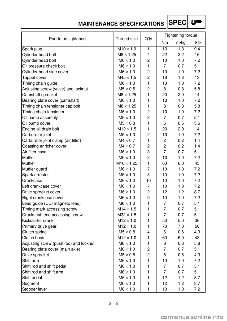
MAINTENANCE SPECIFICATIONS
Part to be tightened Thread size Q’tyTightening torque
Nm m•kg ft•lb
Spark plug M10
´
1.0 1 13 1.3 9.4
Cylinder head bolt M8
´
1.25 4 22 2.2 16
Cylinder head bolt M6
´
1.0 2 10 1.0 7.2
Oil pressure check bolt M6
´
1.0 1 7 0.7 5.1
Cylinder head side cover M6
´
1.0 2 10 1.0 7.2
Tappet cover M45
´
1.5 2 18 1.8 13
Timing chain guide M6
´
1.0 1 10 1.0 7.2
Adjusting screw (valve) and locknut M5
´
0.5 2 8 0.8 5.8
Camshaft sprocket M8
´
1.25 1 20 2.0 14
Bearing plate cover (camshaft) M6
´
1.0 1 10 1.0 7.2
Timing chain tensioner cap bolt M8
´
1.25 1 8 0.8 5.8
Timing chain tensioner M6
´
1.0 2 10 1.0 7.2
Oil pump assembly M6
´
1.0 2 7 0.7 5.1
Oil pump cover M5
´
0.8 1 5 0.5 3.6
Engine oil drain bolt M12
´
1.5 1 20 2.0 14
Carburetor joint M6
´
1.0 2 10 1.0 7.2
Carburetor joint clamp (air filter) M4
´
0.7 1 2 0.2 1.4
Coasting enricher cover M4
´
0.7 2 2 0.2 1.4
Air filter case M6
´
1.0 3 7 0.7 5.1
Muffler M6
´
1.0 2 10 1.0 7.2
Muffler M10
´
1.25 1 60 6.0 43
Muffler guard M6
´
1.0 7 10 1.0 7.2
Spark arrester M6
´
1.0 3 10 1.0 7.2
Crankcase M6
´
1.0 10 10 1.0 7.2
Left crankcase cover M6
´
1.0 7 10 1.0 7.2
Drive sprocket cover M6
´
1.0 2 12 1.2 8.7
Right crankcase cover M6
´
1.0 9 10 1.0 7.2
Lead guide (CDI magneto lead) M6
´
1.0 1 7 0.7 5.1
Timing mark accessing screw M14
´
1.5 1 7 0.7 5.1
Crankshaft end accessing screw M32
´
1.5 1 7 0.7 5.1
Kickstarter crank M12
´
1.0 1 50 5.0 36
Primary drive gear M12
´
1.0 1 70 7.0 50
Clutch spring M5
´
0.8 4 6 0.6 4.3
Clutch boss M12
´
1.0 1 60 6.0 43
Adjusting screw (push rod) and locknut M6
´
1.0 1 8 0.8 5.8
Bearing plate cover (main axle) M6
´
1.0 2 7 0.7 5.1
Drive sprocket M5
´
0.8 2 6 0.6 4.3
Shift arm M6
´
1.0 1 10 1.0 7.2
Shift rod and shift pedal M6
´
1.0 1 7 0.7 5.1
Shift rod and shift arm M6
´
1.0 1 7 0.7 5.1
Shift pedal M6
´
1.0 1 12 1.2 8.7
Segment M6
´
1.0 1 12 1.2 8.7
Stopper lever M6
´
1.0 1 10 1.0 7.2
Page 150 of 442
3 - 11
INSP
ADJ
VALVE CLEARANCE INSPECTION AND ADJUSTMENT
VALVE CLEARANCE INSPECTION AND
ADJUSTMENT
NOTE:
lThe valve clearance should be adjusted
when the engine is cool to the touch.
lThe piston must be at Top Dead Center
(T.D.C.) on compression stroke to check or
adjust the valve clearance.
1. Remove:
lSeat
lFuel tank
Refer to “SEAT, FUEL TANK AND SIDE
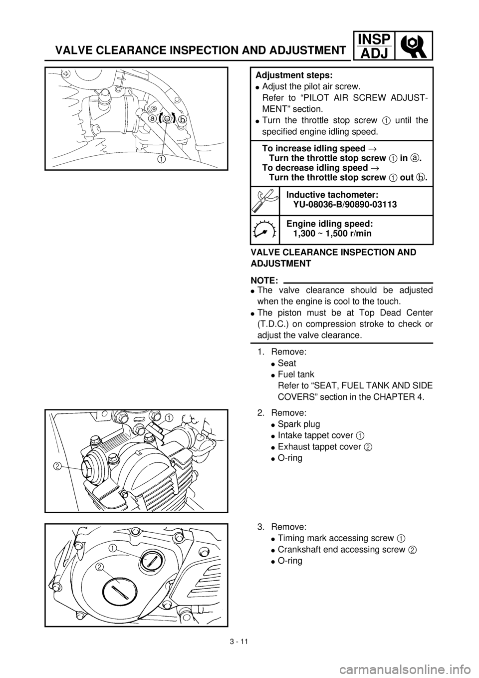
COVERS” section in the CHAPTER 4. Adjustment steps:
lAdjust the pilot air screw.
Refer to “PILOT AIR SCREW ADJUST-
MENT” section.
lTurn the throttle stop screw 1 until the
specified engine idling speed.
To increase idling speed ®
Turn the throttle stop screw 1 in a.
To decrease idling speed ®
Turn the throttle stop screw 1 out b.
Inductive tachometer:
YU-08036-B/90890-03113
Engine idling speed:
1,300 ~ 1,500 r/min
2. Remove:
lSpark plug
lIntake tappet cover 1
lExhaust tappet cover 2
lO-ring
3. Remove:
lTiming mark accessing screw 1
lCrankshaft end accessing screw 2
lO-ring
Page 154 of 442
3 - 13
INSP
ADJ
VALVE CLEARANCE INSPECTION AND ADJUSTMENT
lMeasure the valve clearance.
lIf the clearance is incorrect, repeat above
steps until specified clearance is obtained.
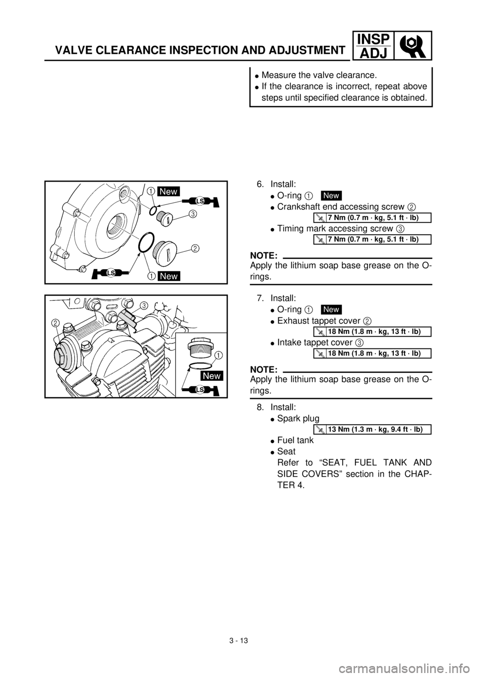
6. Install:
lO-ring 1
lCrankshaft end accessing screw 2
lTiming mark accessing screw 3
NOTE:
Apply the lithium soap base grease on the O-
rings.
New
T R..7 Nm (0.7 m · kg, 5.1 ft · lb)
T R..7 Nm (0.7 m · kg, 5.1 ft · lb)
7. Install:
lO-ring 1
lExhaust tappet cover 2
lIntake tappet cover 3
NOTE:
Apply the lithium soap base grease on the O-
rings.
8. Install:
lSpark plug
lFuel tank
lSeat
Refer to “SEAT, FUEL TANK AND
SIDE COVERS” section in the CHAP-
TER 4.
New
T R..18 Nm (1.8 m · kg, 13 ft · lb)
T R..18 Nm (1.8 m · kg, 13 ft · lb)
T R..13 Nm (1.3 m · kg, 9.4 ft · lb)
Page 202 of 442
4 - 12
ENGCYLINDER HEAD
CYLINDER HEAD
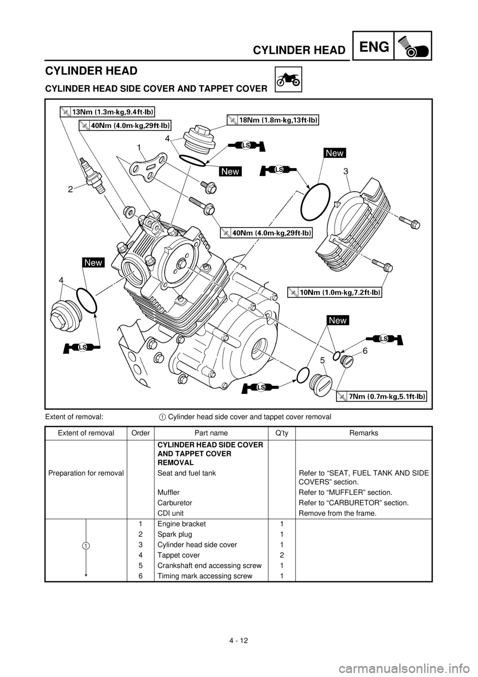
CYLINDER HEAD SIDE COVER AND TAPPET COVER
Extent of removal:1 Cylinder head side cover and tappet cover removal
Extent of removal Order Part name Q’ty Remarks
CYLINDER HEAD SIDE COVER
AND TAPPET COVER
REMOVAL
Preparation for removal Seat and fuel tank Refer to “SEAT, FUEL TANK AND SIDE
COVERS” section.
Muffler Refer to “MUFFLER” section.
Carburetor Refer to “CARBURETOR” section.
CDI unit Remove from the frame.
1 Engine bracket 1
2 Spark plug 1
3 Cylinder head side cover 1
4 Tappet cover 2
5 Crankshaft end accessing screw 1
6 Timing mark accessing screw 1
1
Page 204 of 442
4 - 13
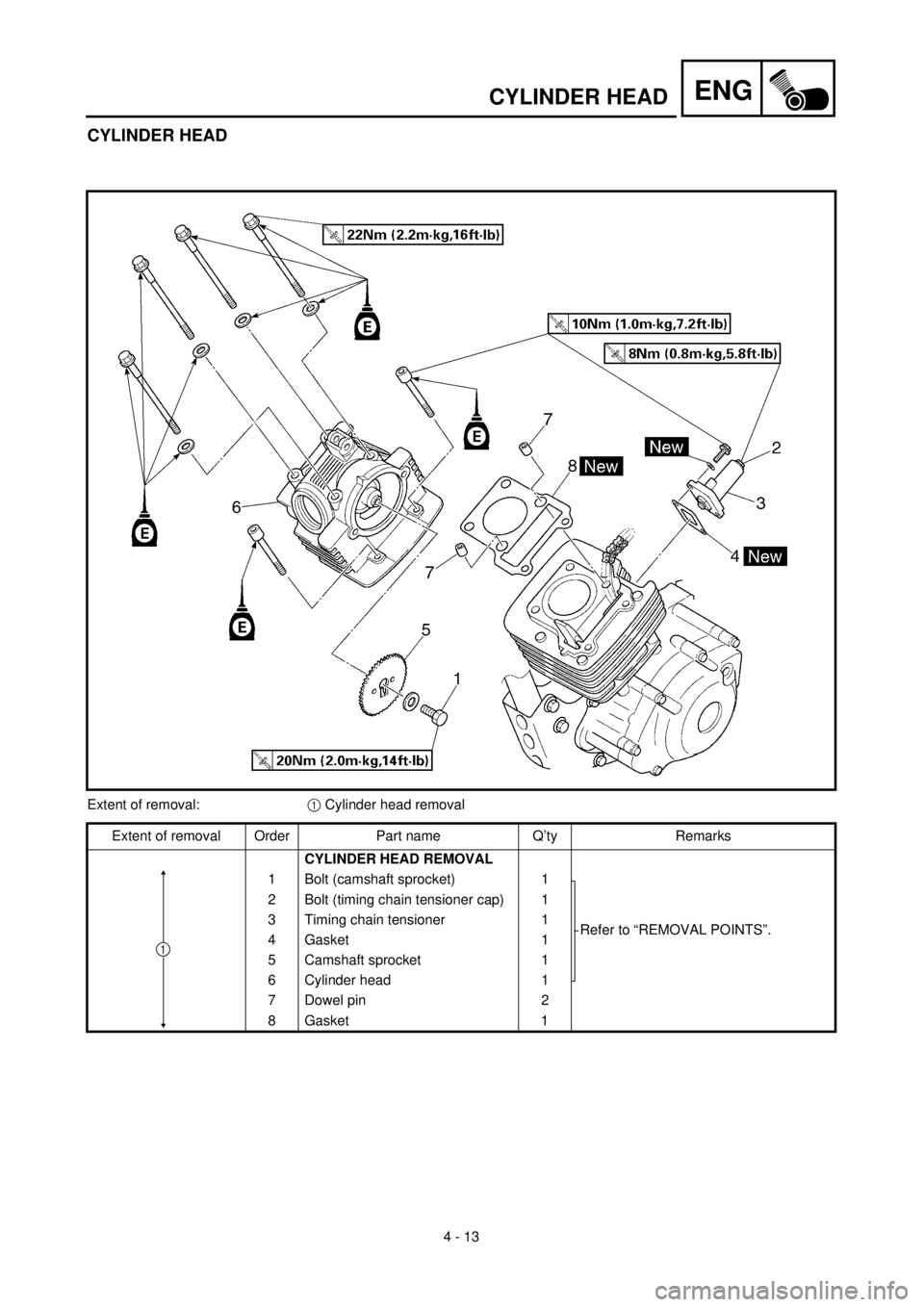
ENGCYLINDER HEAD
CYLINDER HEAD
Extent of removal:1 Cylinder head removal
Extent of removal Order Part name Q’ty Remarks
CYLINDER HEAD REMOVAL
1 Bolt (camshaft sprocket) 1
Refer to “REMOVAL POINTS”. 2 Bolt (timing chain tensioner cap) 1
3 Timing chain tensioner 1
4 Gasket 1
5 Camshaft sprocket 1
6 Cylinder head 1
7 Dowel pin 2
8Gasket
1
1
Page 206 of 442
4 - 14
ENGCYLINDER HEAD
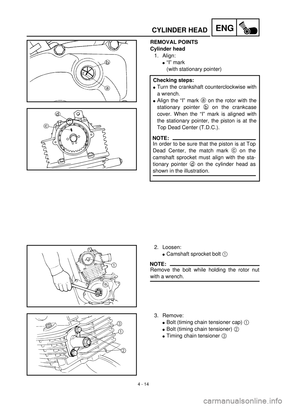
REMOVAL POINTS
Cylinder head
1. Align:
l“I” mark
(with stationary pointer)
Checking steps:
lTurn the crankshaft counterclockwise with
a wrench.
lAlign the “I” mark a on the rotor with the
stationary pointer b on the crankcase
cover. When the “I” mark is aligned with
the stationary pointer, the piston is at the
Top Dead Center (T.D.C.).
NOTE:
In order to be sure that the piston is at Top
Dead Center, the match mark c on the
camshaft sprocket must align with the sta-
tionary pointer d on the cylinder head as
shown in the illustration.
2. Loosen:
lCamshaft sprocket bolt 1
NOTE:
Remove the bolt while holding the rotor nut
with a wrench.
3. Remove:
lBolt (timing chain tensioner cap) 1
lBolt (timing chain tensioner) 2
lTiming chain tensioner 3
Page 208 of 442
4 - 15
ENGCYLINDER HEAD
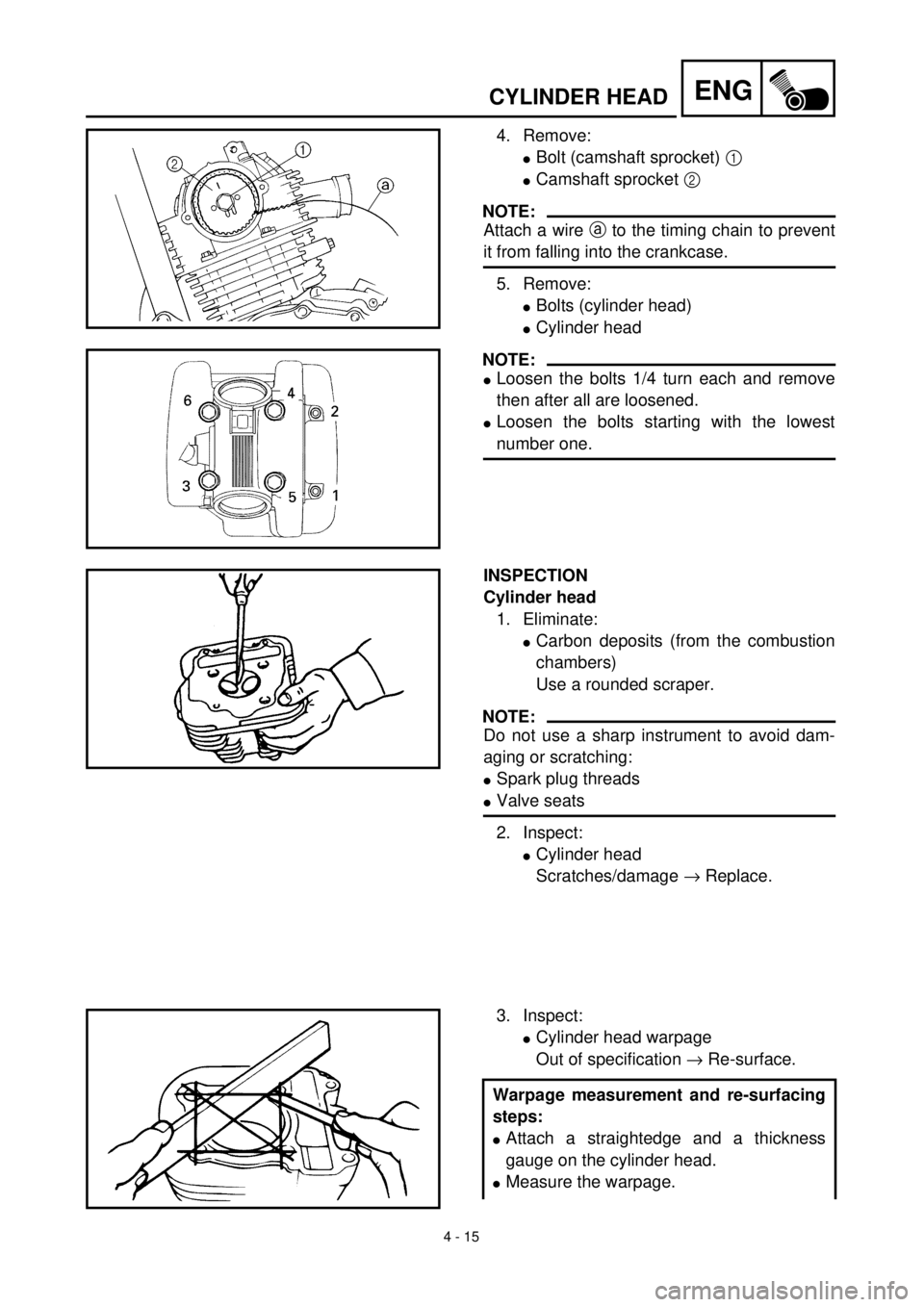
4. Remove:
lBolt (camshaft sprocket) 1
lCamshaft sprocket 2
NOTE:
Attach a wire a to the timing chain to prevent
it from falling into the crankcase.
5. Remove:
lBolts (cylinder head)
lCylinder head
NOTE:
lLoosen the bolts 1/4 turn each and remove
then after all are loosened.
lLoosen the bolts starting with the lowest
number one.
INSPECTION
Cylinder head
1. Eliminate:
lCarbon deposits (from the combustion
chambers)
Use a rounded scraper.
NOTE:
Do not use a sharp instrument to avoid dam-
aging or scratching:
lSpark plug threads
lValve seats
2. Inspect:
lCylinder head
Scratches/damage ® Replace.
3. Inspect:
lCylinder head warpage
Out of specification ® Re-surface.
Warpage measurement and re-surfacing
steps:
lAttach a straightedge and a thickness
gauge on the cylinder head.
lMeasure the warpage.
Page 212 of 442
4 - 17
ENGCYLINDER HEAD
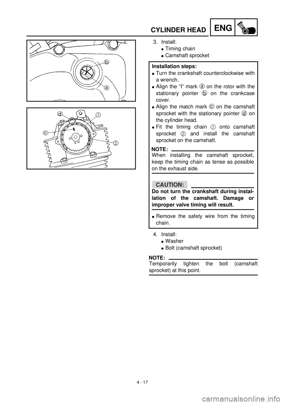
3. Install:
lTiming chain
lCamshaft sprocket
4. Install:
lWasher
lBolt (camshaft sprocket)
NOTE:
Temporarily tighten the bolt (camshaft
sprocket) at this point. Installation steps:
lTurn the crankshaft counterclockwise with
a wrench.
lAlign the “I” mark a on the rotor with the
stationary pointer b on the crankcase
cover.
lAlign the match mark c on the camshaft
sprocket with the stationary pointer d on
the cylinder head.
lFit the timing chain 1 onto camshaft
sprocket 2 and install the camshaft
sprocket on the camshaft.
lRemove the safety wire from the timing
chain.
NOTE:
When installing the camshaft sprocket,
keep the timing chain as tense as possible
on the exhaust side.
CAUTION:
Do not turn the crankshaft during instal-
lation of the camshaft. Damage or
improper valve timing will result.
Page 214 of 442
4 - 18
ENGCYLINDER HEAD
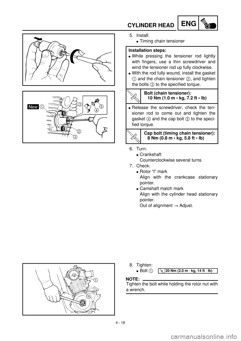
5. Install:
lTiming chain tensioner
6. Turn:
lCrankshaft
Counterclockwise several turns
7. Check:
lRotor “I” mark
Align with the crankcase stationary
pointer.
lCamshaft match mark
Align with the cylinder head stationary
pointer.
Out of alignment ® Adjust. Installation steps:
lWhile pressing the tensioner rod lightly
with fingers, use a thin screwdriver and
wind the tensioner rod up fully clockwise.
lWith the rod fully wound, install the gasket
1 and the chain tensioner 2, and tighten
the bolts 3 to the specified torque.
T R..
Bolt (chain tensioner):
10 Nm (1.0 m • kg, 7.2 ft • lb)
lRelease the screwdriver, check the ten-
sioner rod to come out and tighten the
gasket 4 and the cap bolt 5 to the speci-
fied torque.
T R..
Cap bolt (timing chain tensioner):
8 Nm (0.8 m • kg, 5.8 ft • lb)
8. Tighten:
lBolt 1
NOTE:
Tighten the bolt while holding the rotor nut with
a wrench.
T R..20 Nm (2.0 m · kg, 14 ft · lb)
Page 216 of 442
4 - 19
ENGCYLINDER HEAD
9. Check:
lValve clearance
Out of specification ® Adjust.
Refer to “VALVE CLEARANCE
INSPECTION AND ADJUSTMENT”
section in CHAPTER 3.
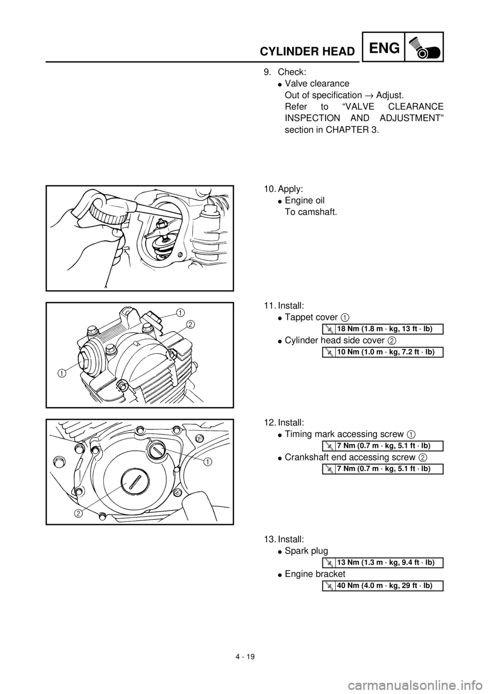
10. Apply:
lEngine oil
To camshaft.
11. Install:
lTappet cover 1
lCylinder head side cover 2
T R..18 Nm (1.8 m · kg, 13 ft · lb)
T R..10 Nm (1.0 m · kg, 7.2 ft · lb)
12. Install:
lTiming mark accessing screw 1
lCrankshaft end accessing screw 2
T R..7 Nm (0.7 m · kg, 5.1 ft · lb)
T R..7 Nm (0.7 m · kg, 5.1 ft · lb)
13. Install:
lSpark plug
lEngine bracket
T R..13 Nm (1.3 m · kg, 9.4 ft · lb)
T R..40 Nm (4.0 m · kg, 29 ft · lb)