ignition YAMAHA TTR125 2000 Notices Demploi (in French)
[x] Cancel search | Manufacturer: YAMAHA, Model Year: 2000, Model line: TTR125, Model: YAMAHA TTR125 2000Pages: 442, PDF Size: 26.34 MB
Page 26 of 442

CHAPTER 4
ENGINE
SEAT, FUEL TANK
AND SIDE COVERS
................................. 4-1
MUFFLER
................................................. 4-2
CARBURETOR
......................................... 4-3
CYLINDER HEAD
................................... 4-12
CAMSHAFT AND ROCKER ARMS
....... 4-20
VALVES AND VALVE SPRINGS
........... 4-24
CYLINDER AND PISTON
....................... 4-32
CLUTCH AND PRIMARY
DRIVEN GEAR
........................................ 4-40
OIL PUMP
............................................... 4-49
KICK AXLE AND SHIFT SHAFT
............ 4-53
CDI MAGNETO
....................................... 4-58
ENGINE REMOVAL
................................ 4-61
CRANKCASE, CRANKSHAFT
AND BALANCER
.................................... 4-65
TRANSMISSION, SHIFT CAM
AND SHIFT FORK
.................................. 4-73
CHAPTER 5
CHASSIS
FRONT WHEEL AND FRONT BRAKE
.... 5-1
REAR WHEEL AND REAR BRAKE
......... 5-8
FRONT FORK
......................................... 5-16
HANDLEBAR
.......................................... 5-25
STEERING
.............................................. 5-31
SWINGARM
............................................ 5-37
REAR SHOCK ABSORBER
................... 5-44
CHAPTER 6
ELECTRICAL
ELECTRICAL COMPONENTS
AND WIRING DIAGRAM
.......................... 6-1
IGNITION SYSTEM
................................... 6-2
Page 40 of 442
GEN
INFO
1 - 8
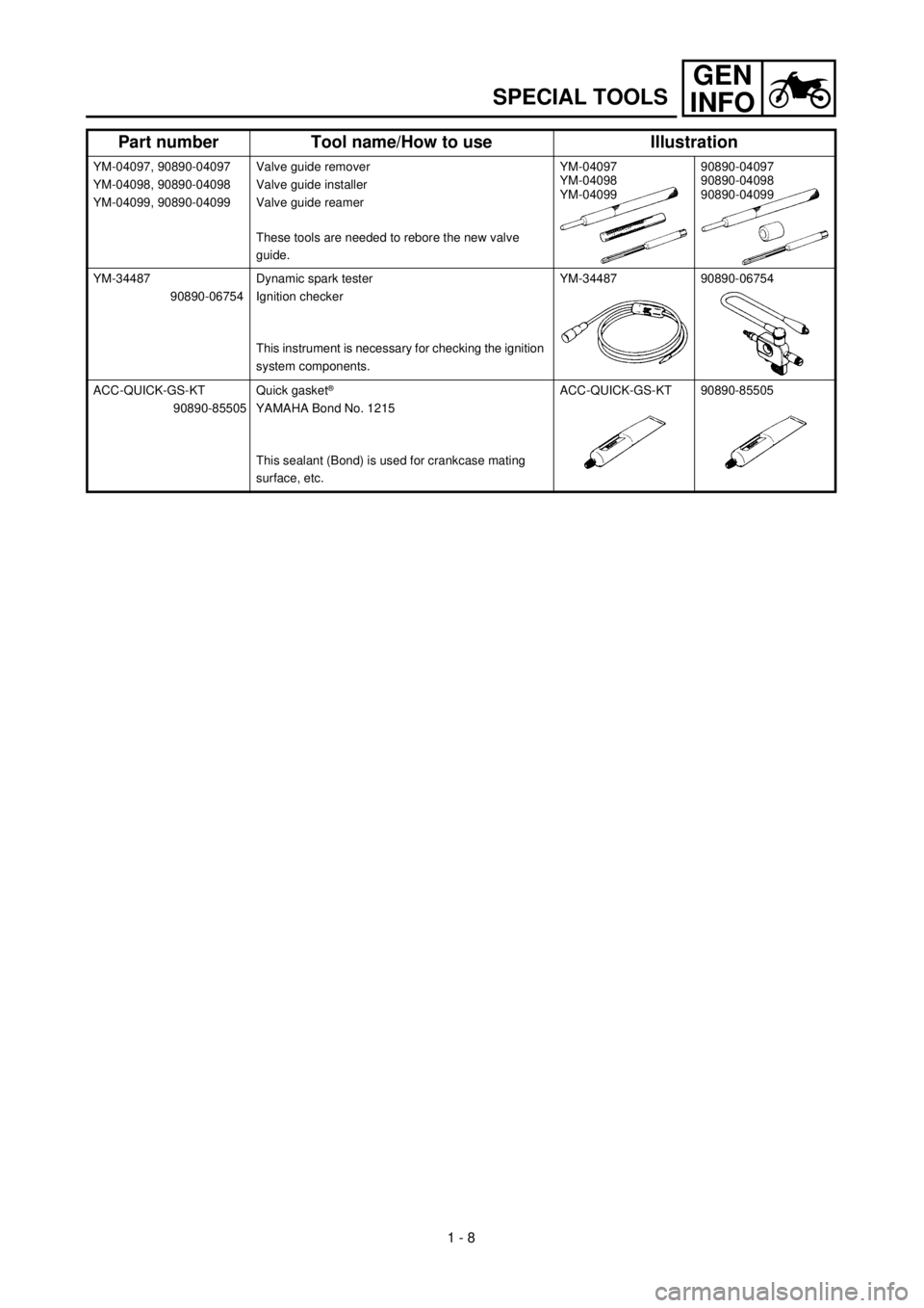
SPECIAL TOOLS
YM-04097, 90890-04097
YM-04098, 90890-04098
YM-04099, 90890-04099Valve guide remover
Valve guide installer
Valve guide reamer
These tools are needed to rebore the new valve
guide.YM-04097
YM-04098
YM-0409990890-04097
90890-04098
90890-04099
YM-34487
90890-06754Dynamic spark tester
Ignition checker
This instrument is necessary for checking the ignition
system components.YM-34487 90890-06754
ACC-QUICK-GS-KT
90890-85505Quick gasket
®
YAMAHA Bond No. 1215
This sealant (Bond) is used for crankcase mating
surface, etc.ACC-QUICK-GS-KT 90890-85505
Part number Tool name/How to use Illustration
Page 70 of 442

SPEC
2 - 3
GENERAL SPECIFICATIONS
Brake:
Front brake type Drum brake
Operation Right hand operation
Rear brake type Drum brake
Operation Right foot operation
Suspension:
Front suspension Telescopic fork
Rear suspension Swingarm (link type monocross suspension)
Shock absorber:
Front shock absorber Coil spring/oil damper
Rear shock absorber Coil spring/gas, oil damper
Wheel travel:
Front wheel travel 180 mm (7.09 in)
Rear wheel travel 160 mm (6.30 in)
Electrical:
Ignition system CDI magneto
Page 83 of 442

SPEC
2 - 16
MAINTENANCE SPECIFICATIONS
EC212300
ELECTRICAL
Item Standard Limit
CDI:
Magneto-model/manufacturer 5HP-00/YAMAHA ----
Charging coil resistance (color) 688 ~ 1,032 W at 20 ˚C (68 ˚F)
(Green-Brown)----
Pickup coil resistance (color) 248 ~ 372 W at 20 ˚C (68 ˚F)
(White/Red)----
CDI unit-model/manufacturer 5HP-00/YAMAHA ----
Ignition coil:
Model/manufacturer 4KJ-10/YAMAHA ----
Minimum spark gap 6 mm (0.24 in) ----
Primary coil resistance 0.18 ~ 0.28 W at 20 ˚C (68 ˚F) ----
Secondary coil resistance 6.3 ~ 9.5 kW at 20 ˚C (68 ˚F) ----
Part to be tightened Thread size Q’tyTightening torque
Nm m•kg ft•lb
Pickup coil M6 ´ 1.0 2 10 1.0 7.2
Blind plug (neutral switch) M10 ´ 1.25 1 20 2.0 14
Stator M6 ´ 1.0 3 10 1.0 7.2
RotorM12 ´ 1.25 1 80 8.0 58
Ignition coil M6 ´ 1.0 2 7 0.7 5.1
Page 120 of 442
2 - 18
SPEC
CABLE ROUTING DIAGRAM
EC240000
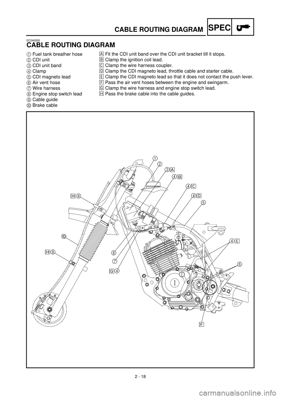
CABLE ROUTING DIAGRAM
1
Fuel tank breather hose
2
CDI unit
3
CDI unit band
4
Clamp
5
CDI magneto lead
6
Air vent hose
7
Wire harness
8
Engine stop switch lead
9
Cable guide
0
Brake cable
Fit the CDI unit band over the CDI unit bracket till it stops.
õ
Clamp the ignition coil lead.
‚
Clamp the wire harness coupler.
ë
Clamp the CDI magneto lead, throttle cable and starter cable.
ä
Clamp the CDI magneto lead so that it does not contact the push lever.
ì
Pass the air vent hoses between the engine and swingarm.
í
Clamp the wire harness and engine stop switch lead.
î
Pass the brake cable into the cable guides.
Page 122 of 442
2 - 19
SPEC
CABLE ROUTING DIAGRAM
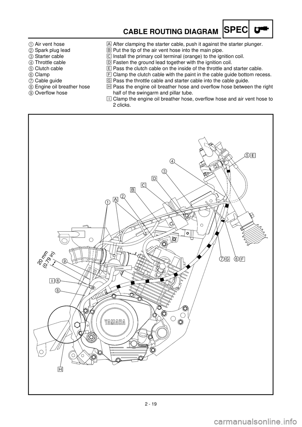
1
Air vent hose
2
Spark plug lead
3
Starter cable
4
Throttle cable
5
Clutch cable
6
Clamp
7
Cable guide
8
Engine oil breather hose
9
Overflow hose
After clamping the starter cable, push it against the starter plunger.
õ
Put the tip of the air vent hose into the main pipe.
‚
Install the primary coil terminal (orange) to the ignition coil.
ë
Fasten the ground lead together with the ignition coil.
ä
Pass the clutch cable on the inside of the throttle and starter cable.
ì
Clamp the clutch cable with the paint in the cable guide bottom recess.
í
Pass the throttle cable and starter cable into the cable guide.
î
Pass the engine oil breather hose and overflow hose between the right
half of the swingarm and pillar tube.
é
Clamp the engine oil breather hose, overflow hose and air vent hose to
2 clicks.
Page 132 of 442

3 - 3
INSP
ADJ
PRE-OPERATION INSPECTION AND MAINTENANCE
PRE-OPERATION INSPECTION AND MAINTENANCE
Before riding for break-in operation or practice, make sure the machine is in good operating condi-
tion.
Before using this machine, check the following points.
GENERAL INSPECTION AND MAINTENANCE
Item Routine Page
FuelCheck that a fresh gasoline is filled in the fuel tank. Check the
fuel line for leakage.P.1-12
Engine oilCheck that the oil level is correct. Check the crankcase for leak-
age.P.3-7 ~ 10
Gear shifter and clutchCheck that gears can be shifted correctly in order and that the
clutch operates smoothly.P.3-4
Throttle grip/housingCheck that the throttle grip operation and free play are correctly
adjusted. Lubricate the throttle grip and housing, if necessary.P.3-4 ~ 5
BrakesCheck the play of front and rear brake and effect of front and
rear brake.P.3-15 ~ 16
Drive chainCheck chain slack and alignment. Check that the chain is lubri-
cated properly.P.3-17 ~ 18
WheelsCheck for excessive wear and tire pressure. Check for loose
spokes and have no excessive play.P.3-20 ~ 21
SteeringCheck that the handlebar can be turned smoothly and have no
excessive play.P.3-21 ~ 23
Front forks and rear shock
absorber assemblyCheck that they operate smoothly and there is no oil leakage. P.3-19 ~ 20
Cables (wires)Check that the clutch and throttle cables move smoothly. Check
that they are not caught when the handlebars are turned or
when the front forks travel up and down.—
Muffler Check that the muffler is tightly mounted and has no cracks. P.4-2
Sprocket Check that the driven sprocket tightening nut is not loose. P.3-16
Lubrication Check for smooth operation. Lubricate if necessary. P.3-24
Bolts and nuts Check the chassis and engine for loose bolts and nuts. —
Lead connectorsCheck that the CDI magneto, CDI unit, and ignition coil are con-
nected tightly.P.1-5
Page 430 of 442
6 - 1
–+ELEC
ELECTRICAL COMPONENTS AND WIRING DIAGRAM
EC600000
ELECTRICAL
EC610000
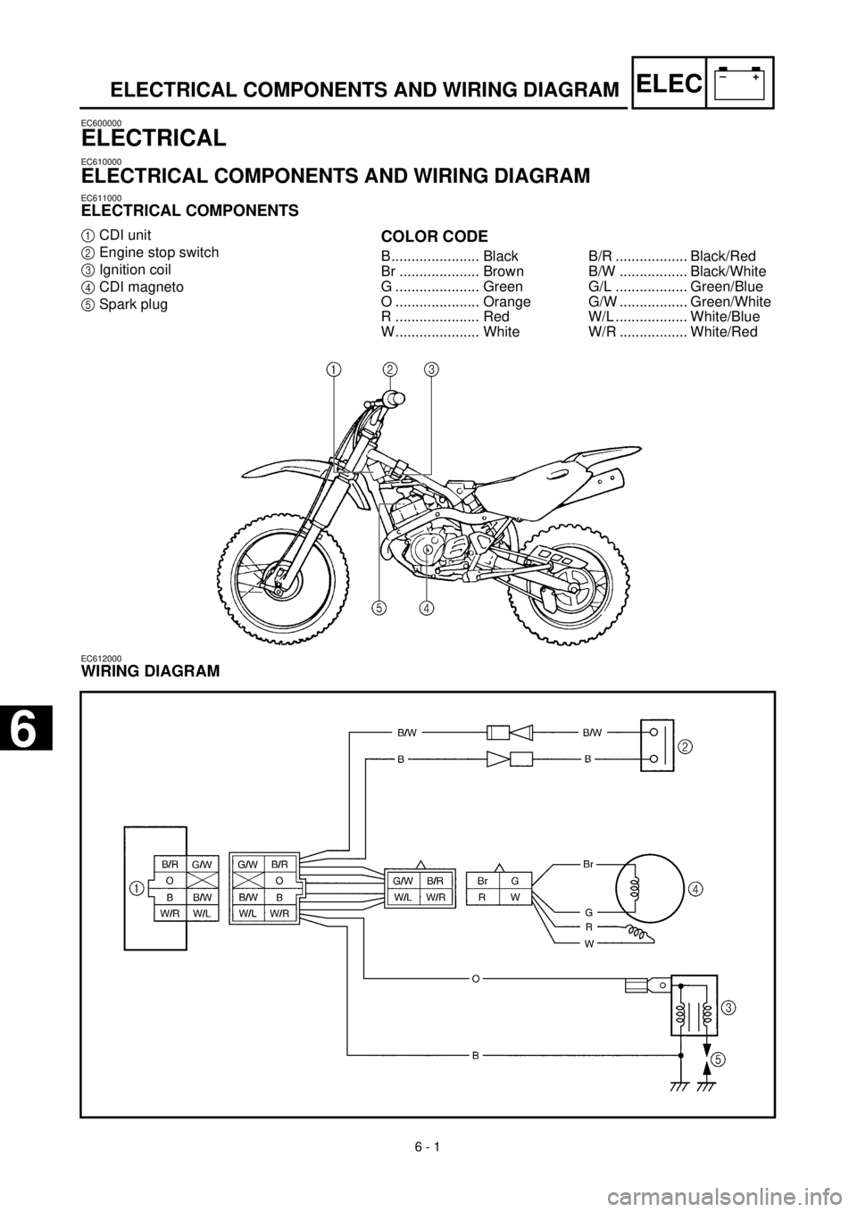
ELECTRICAL COMPONENTS AND WIRING DIAGRAM
EC611000
ELECTRICAL COMPONENTS
1
CDI unit
2
Engine stop switch
3
Ignition coil
4
CDI magneto
5
Spark plug
COLOR CODE
B...................... Black
Br .................... Brown
G ..................... Green
O ..................... Orange
R ..................... Red
W..................... WhiteB/R .................. Black/Red
B/W ................. Black/White
G/L .................. Green/Blue
G/W ................. Green/White
W/L .................. White/Blue
W/R ................. White/Red
EC612000
WIRING DIAGRAM
6
Page 432 of 442
6 - 2
–+ELEC
IGNITION SYSTEM
EC620000
IGNITION SYSTEM
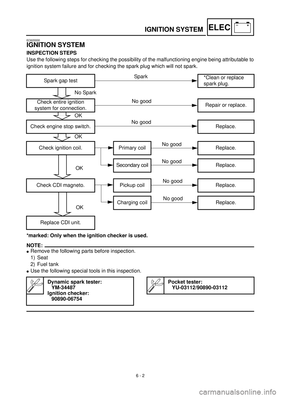
INSPECTION STEPS
Use the following steps for checking the possibility of the malfunctioning engine being attributable to
ignition system failure and for checking the spark plug which will not spark.
*marked: Only when the ignition checker is used.
NOTE:
l
Remove the following parts before inspection.
1) Seat
2) Fuel tank
l
Use the following special tools in this inspection.
Spark gap test*Clean or replace
spark plug.
Check entire ignition
system for connection.Repair or replace.
Check engine stop switch. Replace.
Check ignition coil. Primary coil Replace.
Secondary coilReplace.
Check CDI magneto. Pickup coil Replace.
Charging coil Replace.
Replace CDI unit.
Dynamic spark tester:
YM-34487
Ignition checker:
90890-06754
Pocket tester:
YU-03112/90890-03112
No Spark
OK
OK
OK
OK
Spark
No good
No good
No good
No good
No good
No good
Page 436 of 442
6 - 3
–+ELEC
IGNITION SYSTEM
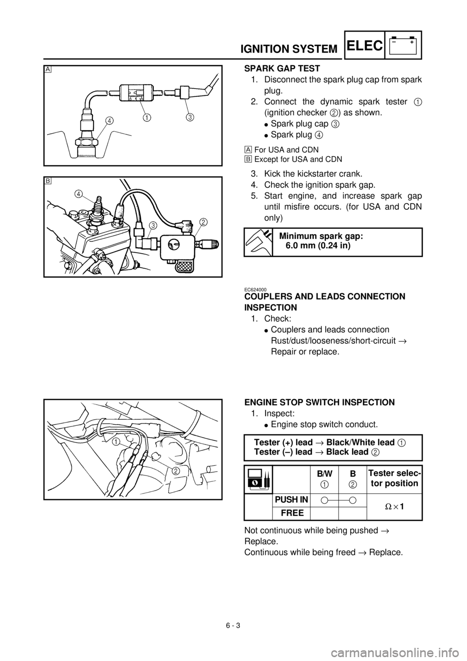
SPARK GAP TEST
1. Disconnect the spark plug cap from spark
plug.
2. Connect the dynamic spark tester
1
(ignition checker
2
) as shown.
l
Spark plug cap
3
l
Spark plug
4
For USA and CDN
õ
Except for USA and CDN
3. Kick the kickstarter crank.
4. Check the ignition spark gap.
5. Start engine, and increase spark gap
until misfire occurs. (for USA and CDN
only)
Minimum spark gap:
6.0 mm (0.24 in)
õ
EC624000
COUPLERS AND LEADS CONNECTION
INSPECTION
1. Check:
l
Couplers and leads connection
Rust/dust/looseness/short-circuit
®
Repair or replace.
ENGINE STOP SWITCH INSPECTION
1. Inspect:
l
Engine stop switch conduct.
Not continuous while being pushed
®
Replace.
Continuous while being freed
®
Replace.
Tester (+) lead
®
Black/White lead
1
Tester (–) lead
®
Black lead
2
B/W
1
B
2
Tester selec-
tor position
PUSH IN
W
´
1
FREE