stop start YAMAHA TTR125 2000 Notices Demploi (in French)
[x] Cancel search | Manufacturer: YAMAHA, Model Year: 2000, Model line: TTR125, Model: YAMAHA TTR125 2000Pages: 442, PDF Size: 26.34 MB
Page 28 of 442
GEN
INFO
1 - 1
DESCRIPTION
EC100000
GENERAL INFORMATION
EC110000
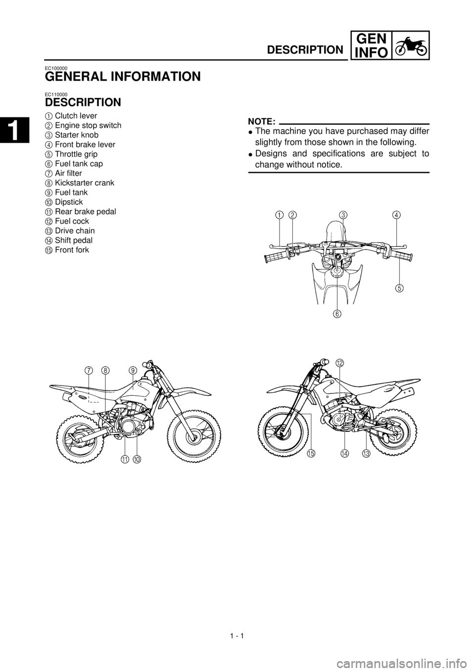
DESCRIPTION
1
Clutch lever
2
Engine stop switch
3
Starter knob
4
Front brake lever
5
Throttle grip
6
Fuel tank cap
7
Air filter
8
Kickstarter crank
9
Fuel tank
0
Dipstick
A
Rear brake pedal
B
Fuel cock
C
Drive chain
D
Shift pedal
E
Front fork
NOTE:
l
The machine you have purchased may differ
slightly from those shown in the following.
l
Designs and specifications are subject to
change without notice.
1
1
Page 29 of 442
GEN
INFO
DESCRIPTION
FAHRZEUGBESCHREIBUNG
ALLGEMEINE ANGABEN
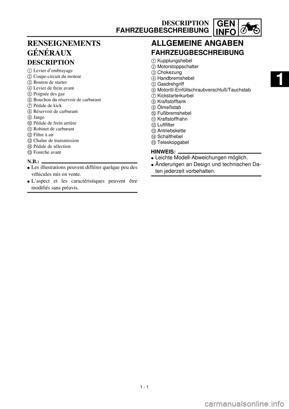
FAHRZEUGBESCHREIBUNG
1
Kupplungshebel
2
Motorstoppschalter
3
Chokezung
4
Handbremshebel
5
Gasdrehgriff
6
Motoröl-Einfüllschraubverschluß/Tauchstab
7
Kickstarterkurbel
8
Kraftstofftank
9
Ölmeßstab
0
Fußbremshebel
A
Kraftstoffhahn
B
Luftfilter
C
Antriebskette
D
Schalthebel
E
Teleskopgabel
HINWEIS:
l
Leichte Modell-Abweichungen möglich.
l
Änderungen an Design und technischen Da-
ten jederzeit vorbehalten.
RENSEIGNEMENTS
GÉNÉRAUX
DESCRIPTION
1
Levier d’embrayage
2
Coupe-circuit du moteur
3
Bouton de starter
4
Levier de frein avant
5
Poignée des gaz
6
Bouchon du réservoir de carburant
7
Pédale de kick
8
Réservoir de carburant
9
Jauge
0
Pédale de frein arrière
A
Robinet de carburant
B
Filtre à air
C
Chaîne de transmission
D
Pédale de sélection
E
Fourche avant
N.B.:
l
Les illustrations peuvent différer quelque peu des
véhicules mis en vente.
l
L’aspect et les caractéristiques peuvent être
modifiés sans préavis.
1 - 1
1
Page 48 of 442
1 - 9
GEN
INFO
CONTROL FUNCTIONS
EC150000
CONTROL FUNCTIONS
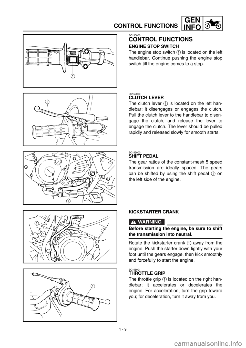
ENGINE STOP SWITCH
The engine stop switch 1 is located on the left
handlebar. Continue pushing the engine stop
switch till the engine comes to a stop.
EC152000
CLUTCH LEVER
The clutch lever 1 is located on the left han-
dlebar; it disengages or engages the clutch.
Pull the clutch lever to the handlebar to disen-
gage the clutch, and release the lever to
engage the clutch. The lever should be pulled
rapidly and released slowly for smooth starts.
EC153000
SHIFT PEDAL
The gear ratios of the constant-mesh 5 speed
transmission are ideally spaced. The gears
can be shifted by using the shift pedal 1 on
the left side of the engine.
KICKSTARTER CRANK
WARNING
Before starting the engine, be sure to shift
the transmission into neutral.
Rotate the kickstarter crank 1 away from the
engine. Push the starter down lightly with your
foot until the gears engage, then kick smoothly
and forcefully to start the engine.
EC155001
THROTTLE GRIP
The throttle grip 1 is located on the right han-
dlebar; it accelerates or decelerates the
engine. For acceleration, turn the grip toward
you; for deceleration, turn it away from you.
Page 49 of 442
GEN
INFOFONCTIONS DES COMMANDES
ARMATUREN UND DEREN FUNKTION
ARMATUREN UND DEREN FUNK-
TION
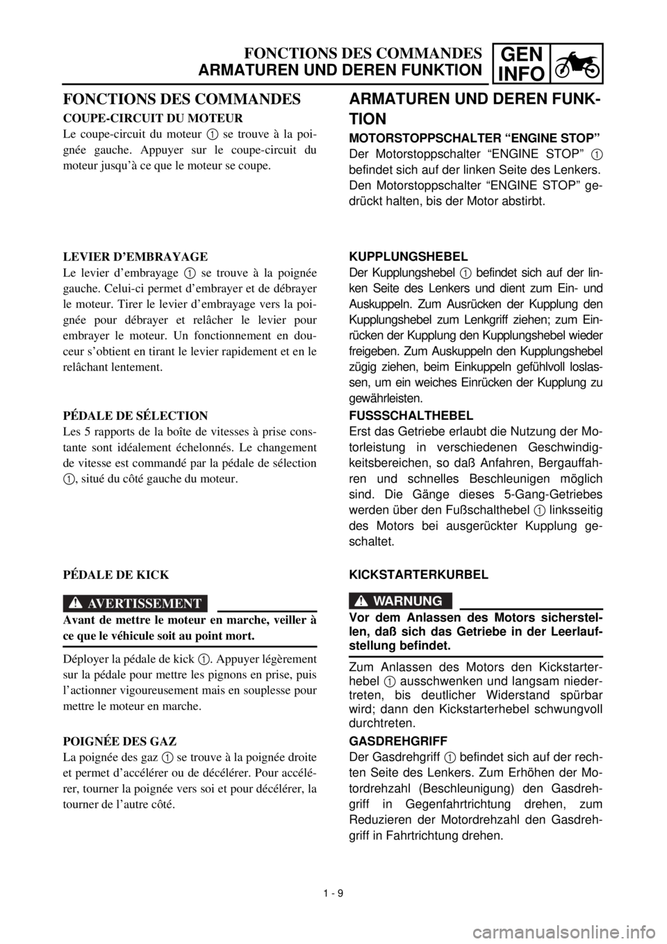
MOTORSTOPPSCHALTER “ENGINE STOP”
Der Motorstoppschalter “ENGINE STOP” 1
befindet sich auf der linken Seite des Lenkers.
Den Motorstoppschalter “ENGINE STOP” ge-
drückt halten, bis der Motor abstirbt.
KUPPLUNGSHEBEL
Der Kupplungshebel 1 befindet sich auf der lin-
ken Seite des Lenkers und dient zum Ein- und
Auskuppeln. Zum Ausrücken der Kupplung den
Kupplungshebel zum Lenkgriff ziehen; zum Ein-
rücken der Kupplung den Kupplungshebel wieder
freigeben. Zum Auskuppeln den Kupplungshebel
zügig ziehen, beim Einkuppeln gefühlvoll loslas-
sen, um ein weiches Einrücken der Kupplung zu
gewährleisten.
FUSSSCHALTHEBEL
Erst das Getriebe erlaubt die Nutzung der Mo-
torleistung in verschiedenen Geschwindig-
keitsbereichen, so daß Anfahren, Bergauffah-
ren und schnelles Beschleunigen möglich
sind. Die Gänge dieses 5-Gang-Getriebes
werden über den Fußschalthebel 1 linksseitig
des Motors bei ausgerückter Kupplung ge-
schaltet.
KICKSTARTERKURBEL
WARNUNG
Vor dem Anlassen des Motors sicherstel-
len, daß sich das Getriebe in der Leerlauf-
stellung befindet.
Zum Anlassen des Motors den Kickstarter-
hebel 1 ausschwenken und langsam nieder-
treten, bis deutlicher Widerstand spürbar
wird; dann den Kickstarterhebel schwungvoll
durchtreten.
GASDREHGRIFF
Der Gasdrehgriff 1 befindet sich auf der rech-
ten Seite des Lenkers. Zum Erhöhen der Mo-
tordrehzahl (Beschleunigung) den Gasdreh-
griff in Gegenfahrtrichtung drehen, zum
Reduzieren der Motordrehzahl den Gasdreh-
griff in Fahrtrichtung drehen.
FONCTIONS DES COMMANDES
COUPE-CIRCUIT DU MOTEUR
Le coupe-circuit du moteur 1 se trouve à la poi-
gnée gauche. Appuyer sur le coupe-circuit du
moteur jusqu’à ce que le moteur se coupe.
LEVIER D’EMBRAYAGE
Le levier d’embrayage 1 se trouve à la poignée
gauche. Celui-ci permet d’embrayer et de débrayer
le moteur. Tirer le levier d’embrayage vers la poi-
gnée pour débrayer et relâcher le levier pour
embrayer le moteur. Un fonctionnement en dou-
ceur s’obtient en tirant le levier rapidement et en le
relâchant lentement.
PÉDALE DE SÉLECTION
Les 5 rapports de la boîte de vitesses à prise cons-
tante sont idéalement échelonnés. Le changement
de vitesse est commandé par la pédale de sélection
1, situé du côté gauche du moteur.
PÉDALE DE KICK
AVERTISSEMENT
Avant de mettre le moteur en marche, veiller à
ce que le véhicule soit au point mort.
Déployer la pédale de kick 1. Appuyer légèrement
sur la pédale pour mettre les pignons en prise, puis
l’actionner vigoureusement mais en souplesse pour
mettre le moteur en marche.
POIGNÉE DES GAZ
La poignée des gaz 1 se trouve à la poignée droite
et permet d’accélérer ou de décélérer. Pour accélé-
rer, tourner la poignée vers soi et pour décélérer, la
tourner de l’autre côté.
1 - 9
Page 58 of 442
1 - 14
GEN
INFO
STARTING AND BREAK-IN
BREAK-IN
Break-in is important to better fit the moving
and sliding parts as well as the installed parts.
It is also important to accustom the rider to the
machine better.
Avoid full-throttle run on a new machine for the
first 5 hours.
After the trial run, check for loose parts, oil
leakage and other problems.
Make full inspection and adjustment especially
of slack cables and drive chain and loose
spokes.
CAUTION:
After the break-in or before each ride, you
must check the entire machine for loose fit-
tings and fasteners as per “TORQUE-
CHECK POINTS”.
Tighten all such fasteners as required.
BREAKING IN AFTER REPLACEMENT
After a part is replaced with a new one, it is
necessary to break it in as in a new machine.
This is required especially when the following
engine-related parts are replaced.
lCylinder
lPiston
lPiston ring
lValve
lCamshaft
lCrankshaft
lClutch
lTransmission gear
lShift fork
* For warming up and inspection during
break-in, refer to “GENERAL INSPECTION
AND MAINTENANCE” and if there is any
problem, stop the engine immediately and
check.
Page 67 of 442
GEN
INFO
STILLEGUNG
Vor einer mehr als zweimonatigen Stillegung
sollten einige Schutzvorkehrungen getroffen
werden, um Schäden zu verhindern. Das
Fahrzeug zuerst gründlich reinigen und dann
folgendermaßen zur Stillegung vorbereiten:
1. Kraftstofftank, Kraftstoffleitungen und
Vergaser-Schwimmerkammer entleeren.
2. Die Zündkerze herausschrauben, unge-
fähr einen Teelöffel Motoröl in die Ker-
zenbohrung geben und die Zündkerze
wieder hineinschrauben. Bei gedrücktem
Motorstoppschalter den Kickstarter mehr-
mals durchtreten, um das Öl in der Zylin-
derlaufbuchse zu verteilen.
3. Die Antriebskette lösen, gründlich reini-
gen und dann schmieren. Die Kette wie-
der montieren oder in einem am Rahmen
befestigten Plastikbeutel aufbewahren.
4. Alle Seilzüge ölen.
5. Das Fahrzeug ganz aufbocken, um beide
Räder vom Boden abzuheben.
6. Eine Plastiktüte über die Schalldämpfer-
öffnung stülpen, um Eindringen von
Feuchtigkeit zu verhindern.
7. Bei Lagerung in extrem feuchter oder
salzhaltiger Luft auf alle Metalloberflä-
chen einen dünnen Ölfilm auftragen.
Jedoch niemals Gummiteile oder den
Sitzbankbezug einölen.
HINWEIS:
Anfallende Reparaturen vor der Stillegung
ausführen.
NETTOYAGE ET REMISAGE
REINIGUNG UND STILLEGUNG
REMISAGE
Si la motocyclette doit être remisée pendant 60
jours ou plus, certaines précautions devront être
observées pour la maintenir en parfait état. Après
un nettoyage complet de la motocyclette, la prépa-
rer comme suit pour le remisage:
1. Vidanger le réservoir de carburant, les canali-
sations de carburant et la cuve à niveau cons-
tant du carburateur.
2. Retirer la bougie, verser environ une cuillerée
à soupe d’huile de moteur SAE 10W-30 dans
le trou de bougie, puis remonter la bougie.
Enfoncer le coupe-circuit du moteur et lancer
quelques fois le moteur en actionnant le kick
afin de répartir l’huile sur la paroi des cylin-
dres.
3. Déposer la chaîne de transmission, la nettoyer
soigneusement dans un dissolvant, puis la
graisser. Remettre en place la chaîne ou la
conserver dans un sachet en plastique (atta-
ché au cadre pour éviter de l’égarer).
4. Lubrifier tous les câbles de commande.
5. Placer un support sous le cadre afin de suréle-
ver les deux roues.
6. Couvrir la sortie du tuyau d’échappement
d’un sachet en plastique pour empêcher la
pénétration d’humidité.
7. Si le véhicule est remisé dans un lieu très
humide ou exposé à l’air marin, enduire tou-
tes les surfaces métalliques extérieures d’une
fine couche d’huile. Ne pas enduire d’huile
les parties en caoutchouc et la housse de selle.
N.B.:
Effectuer toutes les réparations nécessaires avant
de remiser le véhicule.
1 - 17
Page 77 of 442

SPEC
2 - 10
MAINTENANCE SPECIFICATIONS
Part to be tightened Thread size Q’tyTightening torque
Nm m•kg ft•lb
Spark plug M10
´
1.0 1 13 1.3 9.4
Cylinder head bolt M8
´
1.25 4 22 2.2 16
Cylinder head bolt M6
´
1.0 2 10 1.0 7.2
Oil pressure check bolt M6
´
1.0 1 7 0.7 5.1
Cylinder head side cover M6
´
1.0 2 10 1.0 7.2
Tappet cover M45
´
1.5 2 18 1.8 13
Timing chain guide M6
´
1.0 1 10 1.0 7.2
Adjusting screw (valve) and locknut M5
´
0.5 2 8 0.8 5.8
Camshaft sprocket M8
´
1.25 1 20 2.0 14
Bearing plate cover (camshaft) M6
´
1.0 1 10 1.0 7.2
Timing chain tensioner cap bolt M8
´
1.25 1 8 0.8 5.8
Timing chain tensioner M6
´
1.0 2 10 1.0 7.2
Oil pump assembly M6
´
1.0 2 7 0.7 5.1
Oil pump cover M5
´
0.8 1 5 0.5 3.6
Engine oil drain bolt M12
´
1.5 1 20 2.0 14
Carburetor joint M6
´
1.0 2 10 1.0 7.2
Carburetor joint clamp (air filter) M4
´
0.7 1 2 0.2 1.4
Coasting enricher cover M4
´
0.7 2 2 0.2 1.4
Air filter case M6
´
1.0 3 7 0.7 5.1
Muffler M6
´
1.0 2 10 1.0 7.2
Muffler M10
´
1.25 1 60 6.0 43
Muffler guard M6
´
1.0 7 10 1.0 7.2
Spark arrester M6
´
1.0 3 10 1.0 7.2
Crankcase M6
´
1.0 10 10 1.0 7.2
Left crankcase cover M6
´
1.0 7 10 1.0 7.2
Drive sprocket cover M6
´
1.0 2 12 1.2 8.7
Right crankcase cover M6
´
1.0 9 10 1.0 7.2
Lead guide (CDI magneto lead) M6
´
1.0 1 7 0.7 5.1
Timing mark accessing screw M14
´
1.5 1 7 0.7 5.1
Crankshaft end accessing screw M32
´
1.5 1 7 0.7 5.1
Kickstarter crank M12
´
1.0 1 50 5.0 36
Primary drive gear M12
´
1.0 1 70 7.0 50
Clutch spring M5
´
0.8 4 6 0.6 4.3
Clutch boss M12
´
1.0 1 60 6.0 43
Adjusting screw (push rod) and locknut M6
´
1.0 1 8 0.8 5.8
Bearing plate cover (main axle) M6
´
1.0 2 7 0.7 5.1
Drive sprocket M5
´
0.8 2 6 0.6 4.3
Shift arm M6
´
1.0 1 10 1.0 7.2
Shift rod and shift pedal M6
´
1.0 1 7 0.7 5.1
Shift rod and shift arm M6
´
1.0 1 7 0.7 5.1
Shift pedal M6
´
1.0 1 12 1.2 8.7
Segment M6
´
1.0 1 12 1.2 8.7
Stopper lever M6
´
1.0 1 10 1.0 7.2
Page 120 of 442

2 - 18
SPEC
CABLE ROUTING DIAGRAM
EC240000
CABLE ROUTING DIAGRAM
1
Fuel tank breather hose
2
CDI unit
3
CDI unit band
4
Clamp
5
CDI magneto lead
6
Air vent hose
7
Wire harness
8
Engine stop switch lead
9
Cable guide
0
Brake cable
Fit the CDI unit band over the CDI unit bracket till it stops.
õ
Clamp the ignition coil lead.
‚
Clamp the wire harness coupler.
ë
Clamp the CDI magneto lead, throttle cable and starter cable.
ä
Clamp the CDI magneto lead so that it does not contact the push lever.
ì
Pass the air vent hoses between the engine and swingarm.
í
Clamp the wire harness and engine stop switch lead.
î
Pass the brake cable into the cable guides.
Page 121 of 442

SPEC
CHEMINEMENT DES CÂBLES
KABELFÜHRUNG
KABELFÜHRUNG
1
Kraftstofftank-Entlüftungsschlauch
2
C.D.I.-Einheit
3
Halteband C.D.I.-Einheit
4
Klemmschelle
5
Lichtmaschinenrotor-Kabel
6
Entlüftungsschlauch
7
Kabelbaum
8
Motorstoppschalter-Kabel
9
Kabelführung
0
Bremszug
Halteband der C.D.I.-Einheit bis zum Anschlag
über die Halterung der C.D.I.-Einheit schieben.
õ
Zündspulenkabel befestigen.
‚
Kabelbaum-Steckverbinder befestigen.
ë
Lichtmaschinenrotor-Kabel, Gaszug und Choke-
zug befestigen.
ä
Lichtmaschinenrotor-Kabel so befestigen, daß
es den Kupplungs-Druckhebel nicht berührt.
ì
Entlüftungsschläuche zwischen Motor und
Schwinge verlegen.
í
Kabelbaum und Motorstoppschalter-Kabel befe-
stigen.
î
Bremszug durch die Führungen leiten.
CHEMINEMENT DES CÂBLES
1
Reniflard de réservoir de carburant
2
Bloc CDI
3
Sangle du bloc CDI
4
Bride
5
Fil de magnéto CDI
6
Reniflard
7
Faisceau de fils
8
Fil de coupe-circuit du moteur
9
Guide de câble
0
Câble de frein
Faire passer la sangle du bloc CDI le plus loin possi-
ble par-dessus le support du bloc CDI.
õ
Brider le fil de bobine d’allumage.
‚
Brider le coupleur du faisceau de fils.
ë
Brider le fil de magnéto CDI, le câble d’accélération
et le câble de starter.
ä
Brider le fil de magnéto CDI en veillant à ce quil ne
touche pas le levier de poussée.
ì
Faire passer les flexibles de ventilation entre le
moteur et le bras oscillant.
í
Brider le faisceau de fils et le fil du coupe-circuit
d’allumage.
î
Faire passer le câble de frein par les guides de câble.
2 - 18
Page 124 of 442
2 - 20
SPEC
CABLE ROUTING DIAGRAM
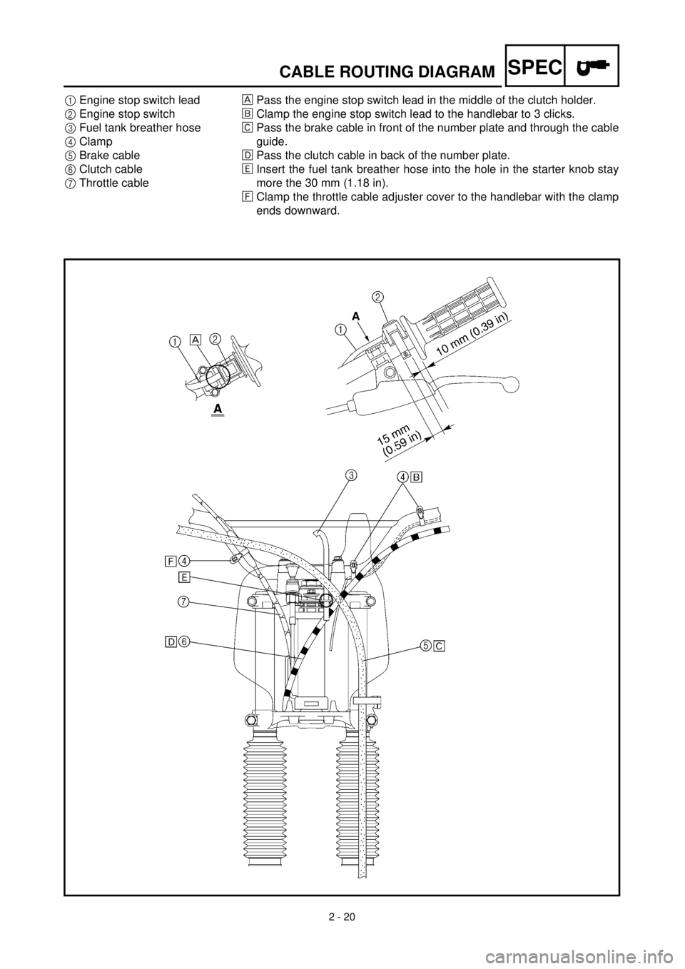
1
Engine stop switch lead
2
Engine stop switch
3
Fuel tank breather hose
4
Clamp
5
Brake cable
6
Clutch cable
7
Throttle cable
Pass the engine stop switch lead in the middle of the clutch holder.
õ
Clamp the engine stop switch lead to the handlebar to 3 clicks.
‚Pass the brake cable in front of the number plate and through the cable
guide.
ëPass the clutch cable in back of the number plate.
äInsert the fuel tank breather hose into the hole in the starter knob stay
more the 30 mm (1.18 in).
ìClamp the throttle cable adjuster cover to the handlebar with the clamp
ends downward.