oil YAMAHA TTR125 2001 Notices Demploi (in French)
[x] Cancel search | Manufacturer: YAMAHA, Model Year: 2001, Model line: TTR125, Model: YAMAHA TTR125 2001Pages: 508, PDF Size: 16.81 MB
Page 490 of 508
5 - 63
CHASREAR SHOCK ABSORBER ASSEMBLY
HANDLING NOTE
WARNING
This rear shock absorber contains high-
pressure nitrogen gas. To prevent the dan-
ger of explosion, read and understand the
following information before handling the
shock absorber.
The manufacturer can not be held responsi-
ble for property damage or personal injury
that may result from improper handling.
1. Never tamper or attempt to open the
rear shock absorber.
2. Never throw the rear shock absorber
into an open flame or other high heat.
The rear shock absorber may explode
as a result of nitrogen gas expansion
and/or damage to the hose.
3. Be careful not to damage any part of
the rear shock absorber. A damaged
rear shock absorber will impair the
damping performance or cause a mal-
function.
4. Take care not to scratch the contact
surface of the piston rod with the cyl-
inder; or oil could leak out.
5. When scrapping the rear shock
absorber, follow the instruction on
disposal.
NOTES ON DISPOSAL (YAMAHA DEALERS
ONLY)
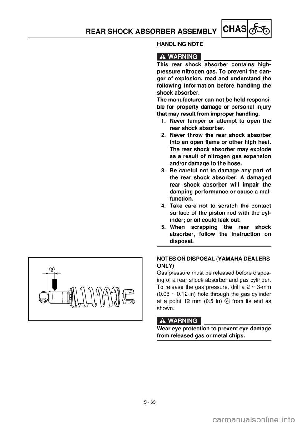
Gas pressure must be released before dispos-
ing of a rear shock absorber and gas cylinder.
To release the gas pressure, drill a 2 ~ 3-mm
(0.08 ~ 0.12-in) hole through the gas cylinder
at a point 12 mm (0.5 in) a from its end as
shown.
WARNING
Wear eye protection to prevent eye damage
from released gas or metal chips.
Page 492 of 508
5 - 64
CHAS
EC583000
REMOVAL POINTS
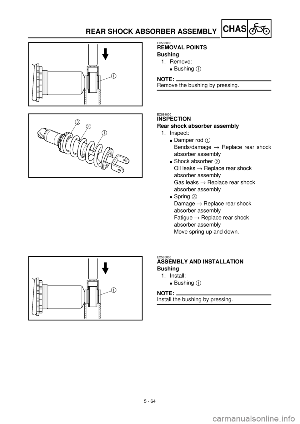
Bushing
1. Remove:
lBushing 1
NOTE:
Remove the bushing by pressing.
EC584000
INSPECTION
Rear shock absorber assembly
1. Inspect:
lDamper rod 1
Bends/damage ® Replace rear shock
absorber assembly
lShock absorber 2
Oil leaks ® Replace rear shock
absorber assembly
Gas leaks ® Replace rear shock
absorber assembly
lSpring 3
Damage ® Replace rear shock
absorber assembly
Fatigue ® Replace rear shock
absorber assembly
Move spring up and down.
EC585000
ASSEMBLY AND INSTALLATION
Bushing
1. Install:
lBushing 1
NOTE:
Install the bushing by pressing.
REAR SHOCK ABSORBER ASSEMBLY
Page 496 of 508
6 - 1
–+ELEC
* The illustration shows the TT-R125LW
ELECTRICAL COMPONENTS AND WIRING DIAGRAM
EC600000
ELECTRICAL
EC610000
ELECTRICAL COMPONENTS AND WIRING DIAGRAM
EC611000
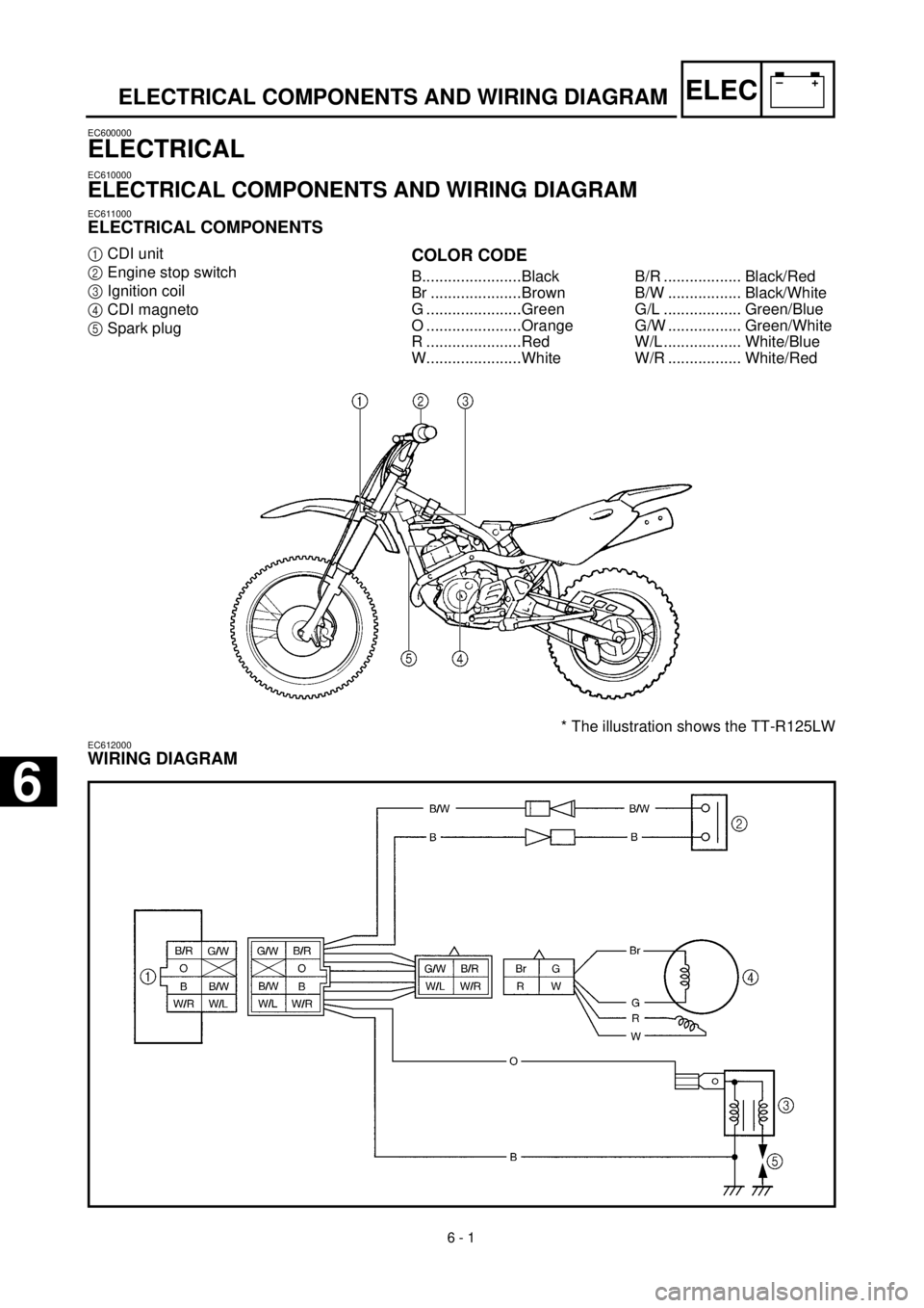
ELECTRICAL COMPONENTS
1
CDI unit
2
Engine stop switch
3
Ignition coil
4
CDI magneto
5
Spark plug
COLOR CODE
B.......................Black
Br .....................Brown
G ......................Green
O ......................Orange
R ......................Red
W......................WhiteB/R .................. Black/Red
B/W ................. Black/White
G/L .................. Green/Blue
G/W ................. Green/White
W/L .................. White/Blue
W/R ................. White/Red
EC612000
WIRING DIAGRAM
6
Page 498 of 508
6 - 2
–+ELEC
IGNITION SYSTEM
EC620000
IGNITION SYSTEM
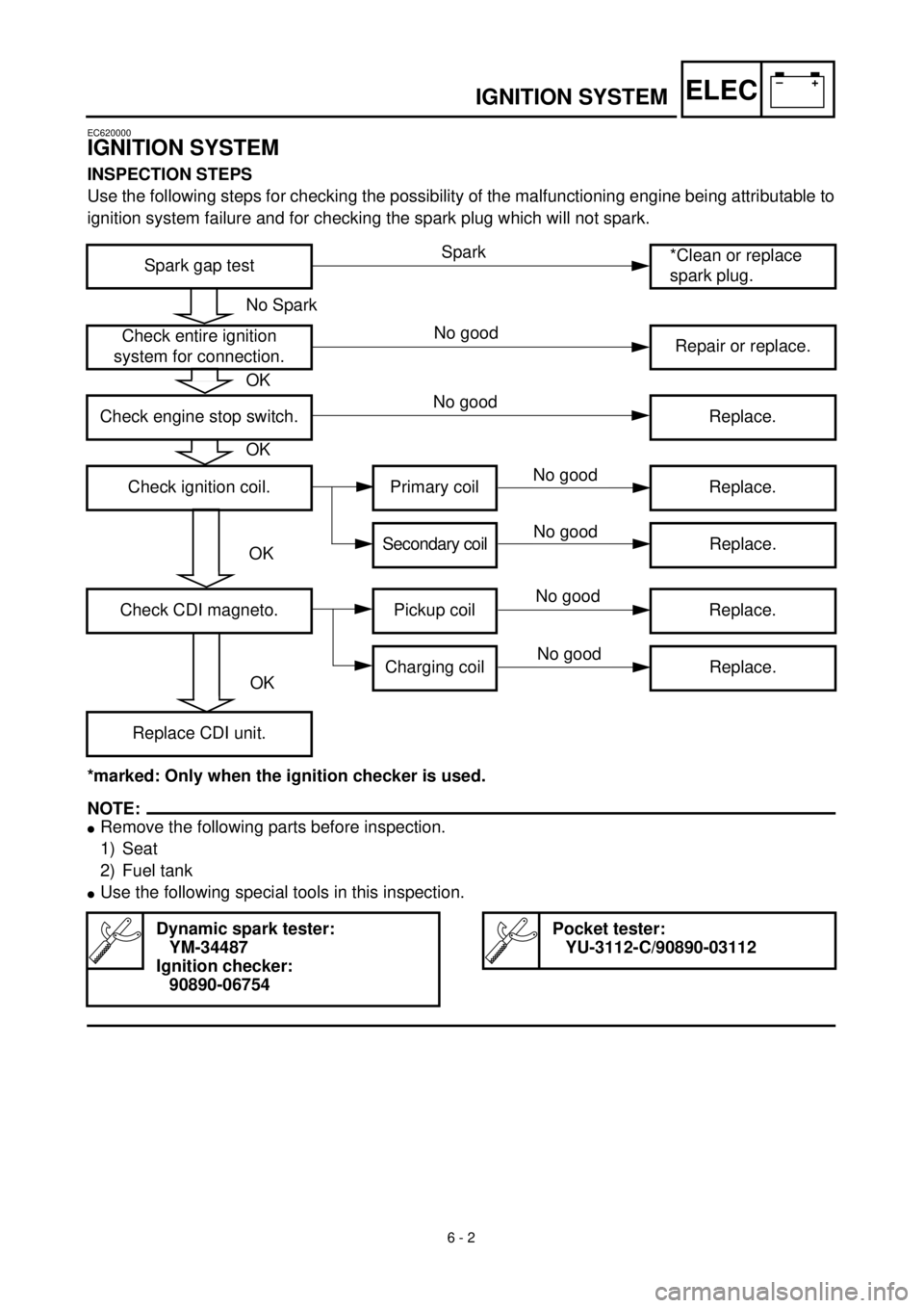
INSPECTION STEPS
Use the following steps for checking the possibility of the malfunctioning engine being attributable to
ignition system failure and for checking the spark plug which will not spark.
*marked: Only when the ignition checker is used.
NOTE:
l
Remove the following parts before inspection.
1) Seat
2) Fuel tank
l
Use the following special tools in this inspection.
Spark gap test*Clean or replace
spark plug.
Check entire ignition
system for connection.Repair or replace.
Check engine stop switch. Replace.
Check ignition coil. Primary coil Replace.
Secondary coilReplace.
Check CDI magneto. Pickup coil Replace.
Charging coil Replace.
Replace CDI unit.
Dynamic spark tester:
YM-34487
Ignition checker:
90890-06754
Pocket tester:
YU-3112-C/90890-03112
No Spark
OK
OK
OK
OK
Spark
No good
No good
No good
No good
No good
No good
Page 504 of 508
6 - 4
–+ELEC
IGNITION SYSTEM
EC626002
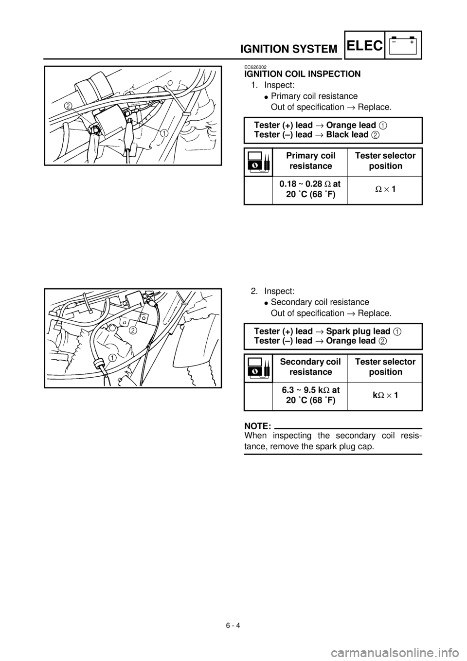
IGNITION COIL INSPECTION
1. Inspect:
l
Primary coil resistance
Out of specification
®
Replace.
Tester (+) lead
®
Orange lead
1
Tester (–) lead
®
Black lead
2
Primary coil
resistanceTester selector
position
0.18 ~ 0.28
W
at
20 ˚C (68 ˚F)
W
´
1
2. Inspect:
l
Secondary coil resistance
Out of specification
®
Replace.
NOTE:
When inspecting the secondary coil resis-
tance, remove the spark plug cap.
Tester (+) lead
®
Spark plug lead
1
Tester (–) lead
®
Orange lead
2
Secondary coil
resistanceTester selector
position
6.3 ~ 9.5 k
W
at
20 ˚C (68 ˚F)k
W
´
1
Page 506 of 508
6 - 5
–+ELEC
IGNITION SYSTEM
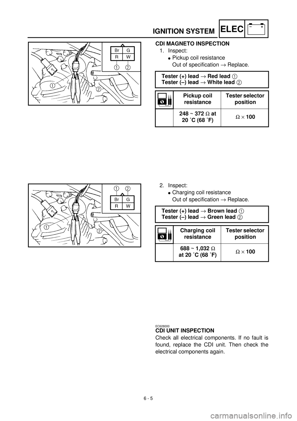
CDI MAGNETO INSPECTION
1. Inspect:
l
Pickup coil resistance
Out of specification ® Replace.
Tester (+) lead ® Red lead 1
Tester (–) lead ® White lead 2
Pickup coil
resistanceTester selector
position
248 ~ 372 W at
20 ˚C (68 ˚F)W ´ 100
2. Inspect:
lCharging coil resistance
Out of specification ® Replace.
Tester (+) lead ® Brown lead 1
Tester (–) lead ® Green lead 2
Charging coil
resistanceTester selector
position
688 ~ 1,032 W
at 20 ˚C (68 ˚F)W ´ 100
EC628000
CDI UNIT INSPECTION
Check all electrical components. If no fault is
found, replace the CDI unit. Then check the
electrical components again.