ECU YAMAHA TTR125 2002 Betriebsanleitungen (in German)
[x] Cancel search | Manufacturer: YAMAHA, Model Year: 2002, Model line: TTR125, Model: YAMAHA TTR125 2002Pages: 509, PDF-Größe: 16.83 MB
Page 7 of 509
WICHTIGER HINWEIS
Dieses Fahrzeug ist ausschließlich für den Ge-
brauch abseits öffentlicher Straßen durch jun-
ge Fahrer unter Beaufsichtigung von Erwach-
senen vorgesehen. Der Einsatz dieses
Fahrzeugs auf öffentlichen Straßen, Wegen
oder Schnellstraßen ist nicht gestattet.
Der Einsatz abseits der Straßen auf öffentli-
chem Gelände kann verboten sein. Bitte vor
Fahrtantritt die örtlichen Bestimmungen prü-
fen.
1. Kraftstoff ist leicht entzündlich.
Daher:
* Motor beim Auftanken immer abstel-
len.
* Beim Auftanken darauf achten, daß
kein Kraftstoff auf Motor, Krümmer
oder Schalldämpfer verschüttet
wird.
* Beim Auftanken darauf achten, daß
nicht geraucht wird und sich keine
offenen Flammen in der Nähe befin-
den.
2. Falls Kraftstoff geschluckt wurde,
große Mengen an Kraftstoffdampf ein-
geatmet wurden oder Kraftstoff in die
Augen gelangt ist, muß unverzüglich
ein Arzt aufgesucht werden. Falls
Kraftstoff auf Haut oder Kleidung
gelangt, sofort mit Wasser und Seife
abwaschen und die Kleidung wech-
seln.
3. Den Motor immer abstellen, wenn das
Fahrzeug unbeaufsichtigt ist. Beim
Parken des Fahrzeuges folgende
Punkte beachten:
* Motor und Auspuffanlage werden
sehr heiß. Darum so parken, daß
Fußgänger oder Kinder die heißen
Teile nicht versehentlich berühren
können.
* Das Fahrzeug nicht auf abschüssi-
gem oder weichem Untergrund
abstellen, damit es nicht umfallen
kann.
SICHERHEITSINFORMATION
REMARQUE IMPORTANTE
Ce véhicule est conçu uniquement pour une utilisa-
tion tout-terrain par des pilotes très jeunes roulant
sous la surveillance d’un adulte, après avoir reçu
les instructions nécessaires par un adulte. L’utilisa-
tion de cette machine sur la voie publique (rue,
route, autoroute, etc.) est interdite.
L’utilisation de ce véhicule sur des terrains publics
peut être illégale. Avant utilisation, prendre con-
naissance des réglementations locales.
1. L’ESSENCE EST UN PRODUIT TRÈS
INFLAMMABLE:
* Toujours couper le moteur avant de
faire le plein.
* Bien veiller à ne pas renverser
d’essence sur le moteur ou le tuyau et
pot d’échappement en faisant le plein.
* Ne pas faire le plein en fumant ou à
proximité d’une flamme.
2. En cas d’ingestion d’essence, d’inhalation
importante de vapeur d’essence ou d’écla-
boussure dans les yeux, consulter immé-
diatement un médecin. En cas
d’éclaboussure d’essence sur la peau ou
les vêtements, se laver immédiatement à
l’eau et au savon et changer de vêtements.
3. Toujours couper le moteur avant de lais-
ser le véhicule sans surveillance. Au
moment de se garer, être attentif aux
points suivants:
* Le moteur ainsi que les éléments du sys-
tème d’échappement risquent d’être
chauds. Garer le véhicule à un endroit
où les piétons et particulièrement les
enfants ne risquent pas de le toucher.
* Ne pas stationner dans une pente ou sur
un sol meuble où la machine pourrait se
renverser.
INFORMATION DE SECURITE
Page 11 of 509

SICHERHEITSINFORMATION
1. Das Fahrzeug nicht auf der Straße fahren.
2. Den Motor nicht in geschlossenen Räumen
starten.
3. Dieses Fahrzeug ist nur für eine Person
zugelassen. Zweipersonen-Betrieb ist nicht
gestattet.
4. Sicheres Fahren kann man lernen. Im
Zweifelsfall die Eltern fragen.
5. Beim Fahren immer einen Helm tragen.
1
Helm
2
Schutzbrille
3
Mundschutz
4
Motorrad-Handschuhe
5
Motorradstiefel
6
Motocross-Hose
7
Langärmeliges Trainingshemd
8
Brustschutz
INFORMATION DE SECURITE
1. Ne pas rouler sur la route.
2. Ne pas faire tourner le moteur dans un bâti-
ment.
3. Il s’agit d’une moto à une seule place. Ne
jamais transporter de passager.
4. Il est important d’apprendre à conduire correc-
tement. Ne pas hésiter à poser des questions à
l’instructeur.
5. Toujours porter un casque ainsi qu’une tenue
de moto adéquate pour rouler.
1
Casque
2
Lunettes
3
Protection pour la bouche
4
Gants
5
Bottes
6
Pantalon de motard
7
Veste à longue manches
8
Protection
Page 17 of 509
COMMENT UTILISER CE
MANUEL
INFORMATIONS IMPORTANTES
Le symbole de danger incite à ÊTRE VIGILANT
AFIN DE GARANTIR SA SÉCURITÉ!
Le non-respect des instructions AVERTISSE-
MENT peut entraîner de sérieuses blessures ou la
mort du pilote de la machine, d’un passant ou d’une
personne inspectant ou réparant la machine.
Un ATTENTION indique les précautions particu-
lières à prendre pour éviter d’endommager le véhi-
cule.
N.B.:
Un N.B. fournit les renseignements nécessaires à la
clarification et la simplification des diverses opéra-
tions.
TROUVER LA PAGE RECHERCHÉE
1. Ce manuel comprend six chapitres: “Rensei-
gnements généraux”, “Caractéristiques”,
“Contrôles et réglages courants”, “Moteur”,
“Partie cycle” et “Partie électrique”.
2. La table des matières se trouve au début du
manuel. Lire la table des matières et la sec-
tion “Format du manuel” avant de rechercher
un chapitre et un point particulier.
Arquer le manuel à son bord, comme illustré,
pour trouver le symbole du chapitre recher-
ché, puis aller à la page du thème recherché.
AVERTISSEMENT
ATTENTION:
BENUTZERHINWEISE
KENNZEICHNUNG
WICHTIGER HINWEISE
Das Ausrufezeichen bedeutet: “GEFAHR!
Achten Sie auf Ihre Sicherheit!”
Ein Mißachten dieser Warnhinweise bringt
Fahrer, Mechaniker und andere Personen in
Verletzungs- oder Lebensgefahr.
Hierunter sind Vorsichtsmaßnahmen zum
Schutz des Fahrzeugs vor Schäden aufge-
führt.
HINWEIS:
Ein HINWEIS gibt Zusatzinformationen und
Tips, um bestimmte Vorgänge oder Arbeiten
zu vereinfachen.
INFORMATION AUFFINDEN
1. Diese Anleitung umfaßt sechs Kapitel: 1.
Allgemeine Angaben – 2. Technische
Daten – 3. Regelmäßige Inspektionen
und Einstellarbeiten – 4. Motor – 5. Fahr-
werk – 6. Elektrische Anlage.
2. Dem ersten Kapitel geht ein Inhaltver-
zeichnis voran. Machen Sie sich mit dem
Inhalt und Aufbau der Anleitung vertraut,
bevor Sie nach bestimmten Angaben su-
chen. Halten Sie das Buch wie in der Ab-
bildung gezeigt, um das Auffinden der
einzelnen Kapitel zu erleichtern.
WARNUNG
ACHTUNG:
Page 39 of 509
1 - 7
GEN
INFO
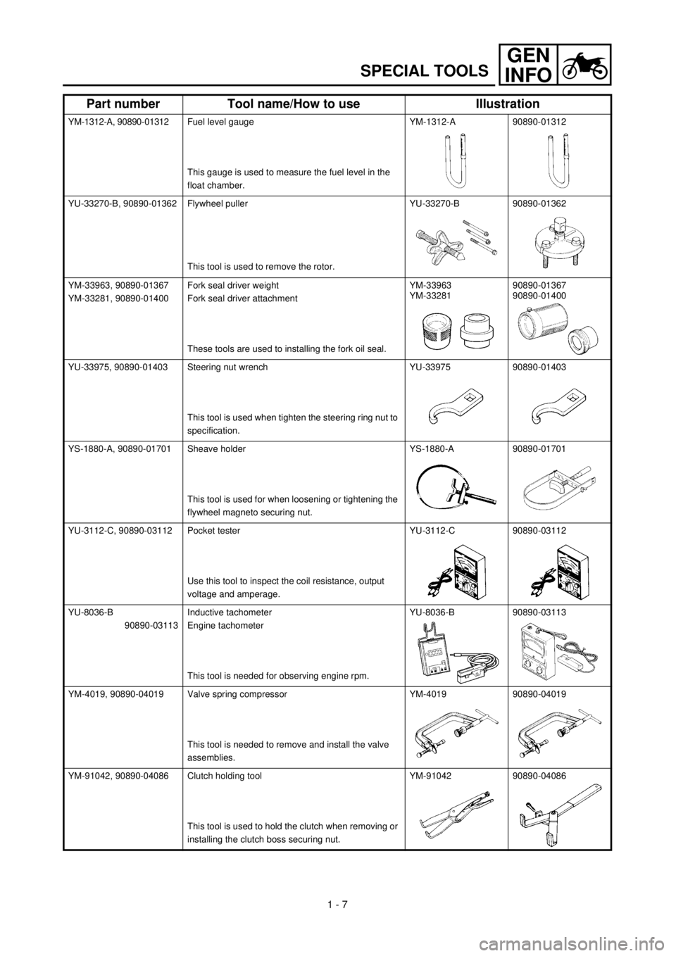
SPECIAL TOOLS
YM-1312-A, 90890-01312Fuel level gauge
This gauge is used to measure the fuel level in the
float chamber.YM-1312-A 90890-01312
YU-33270-B, 90890-01362 Flywheel puller
This tool is used to remove the rotor.YU-33270-B 90890-01362
YM-33963, 90890-01367
YM-33281, 90890-01400Fork seal driver weight
Fork seal driver attachment
These tools are used to installing the fork oil seal.YM-33963
YM-3328190890-01367
90890-01400
YU-33975, 90890-01403 Steering nut wrench
This tool is used when tighten the steering ring nut to
specification.YU-33975 90890-01403
YS-1880-A, 90890-01701 Sheave holder
This tool is used for when loosening or tightening the
flywheel magneto securing nut.YS-1880-A 90890-01701
YU-3112-C, 90890-03112 Pocket tester
Use this tool to inspect the coil resistance, output
voltage and amperage.YU-3112-C 90890-03112
YU-8036-B
90890-03113Inductive tachometer
Engine tachometer
This tool is needed for observing engine rpm.YU-8036-B 90890-03113
YM-4019, 90890-04019 Valve spring compressor
This tool is needed to remove and install the valve
assemblies.YM-4019 90890-04019
YM-91042, 90890-04086 Clutch holding tool
This tool is used to hold the clutch when removing or
installing the clutch boss securing nut.YM-91042 90890-04086
Part number Tool name/How to use Illustration
Page 66 of 509
1 - 17
GEN
INFO
CLEANING AND STORAGE
EC1B0000
CLEANING AND STORAGE
EC1B1000
CLEANING
Frequent cleaning of your machine will
enhance its appearance, maintain good over-
all performance, and extend the life of many
components.
1. Before washing the machine, block off
the end of the exhaust pipe to prevent
water from entering. A plastic bag
secured with a rubber band may be used
for this purpose.
2. If the engine is excessively greasy, apply
some degreaser to it with a paint brush.
Do not apply degreaser to the chain,
sprockets, or wheel axles.
3. Rinse the dirt and degreaser off with a
garden hose; use only enough pressure
to do the job.
CAUTION:
Excessive hose pressure may cause water
seepage and contamination of wheel bear-
ings, front forks, brakes and transmission
seals. Many expensive repair bills have
resulted from improper high pressure
detergent applications such as those avail-
able in coin-operated car washers.
4. After the majority of the dirt has been
hosed off, wash all surfaces with warm
water and a mild detergent. Use an old
toothbrush to clean hard-to-reach places.
5. Rinse the machine off immediately with
clean water, and dry all surfaces with a
soft towel or cloth.
6. Immediately after washing, remove
excess water from the chain with a paper
towel and lubricate the chain to prevent
rust.
7. Clean the seat with a vinyl upholstery
cleaner to keep the cover pliable and
glossy.
8. Automotive wax may be applied to all
painted or chromed surfaces. Avoid com-
bination cleaner-waxes, as they may con-
tain abrasives.
9. After completing the above, start the
engine and allow it to idle for several min-
utes.
Page 270 of 509
4 - 31
ENGVALVES AND VALVE SPRINGS
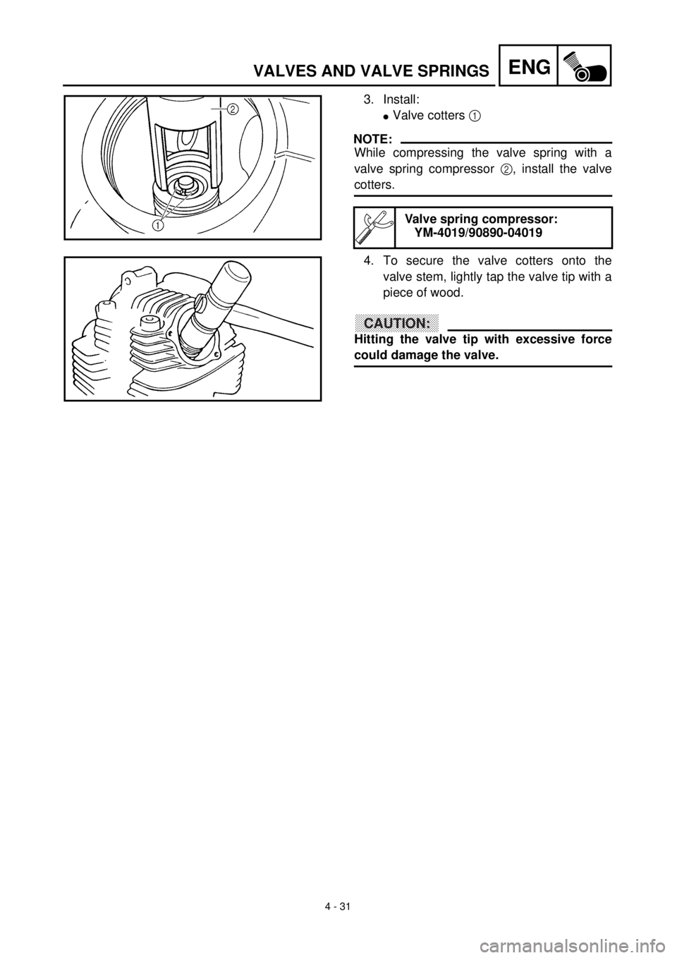
3. Install:
lValve cotters 1
NOTE:
While compressing the valve spring with a
valve spring compressor 2, install the valve
cotters.
Valve spring compressor:
YM-4019/90890-04019
4. To secure the valve cotters onto the
valve stem, lightly tap the valve tip with a
piece of wood.
CAUTION:
Hitting the valve tip with excessive force
could damage the valve.
Page 345 of 509
4 - 68
ENG
CARTER-MOTEUR, VILEBREQUIN ET BALANCIER
KURBELGEHÄUSE, KURBELWELLE UND AUSGLEICHSWELLE
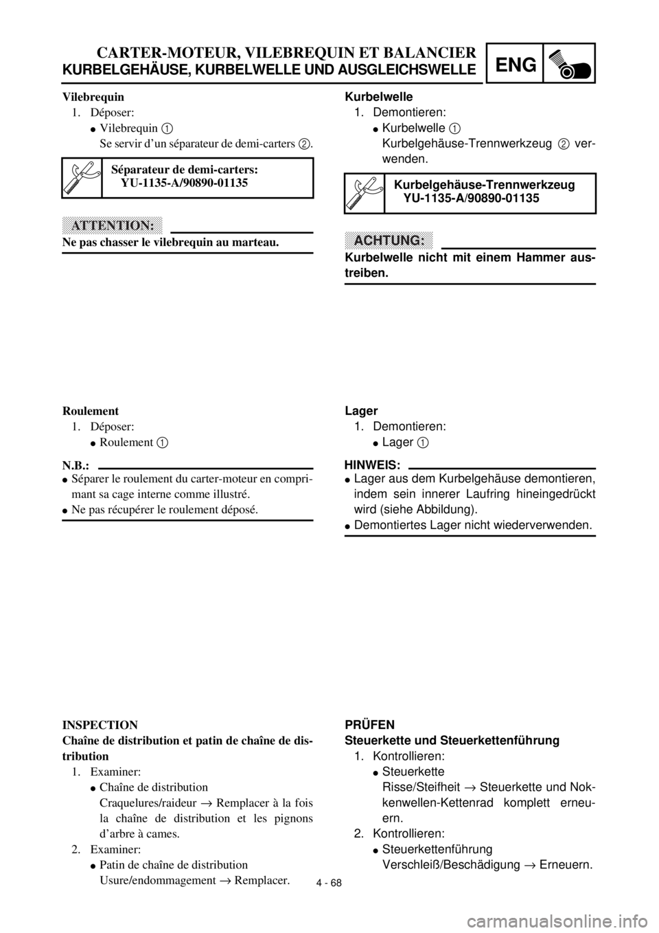
Kurbelwelle
1. Demontieren:
lKurbelwelle 1
Kurbelgehäuse-Trennwerkzeug 2 ver-
wenden.
ACHTUNG:
Kurbelwelle nicht mit einem Hammer aus-
treiben.
Kurbelgehäuse-Trennwerkzeug
YU-1135-A/90890-01135
Lager
1. Demontieren:
lLager 1
HINWEIS:
lLager aus dem Kurbelgehäuse demontieren,
indem sein innerer Laufring hineingedrückt
wird (siehe Abbildung).
lDemontiertes Lager nicht wiederverwenden.
PRÜFEN
Steuerkette und Steuerkettenführung
1. Kontrollieren:
lSteuerkette
Risse/Steifheit ® Steuerkette und Nok-
kenwellen-Kettenrad komplett erneu-
ern.
2. Kontrollieren:
lSteuerkettenführung
Verschleiß/Beschädigung ® Erneuern. Vilebrequin
1. Déposer:
lVilebrequin 1
Se servir d’un séparateur de demi-carters 2.
ATTENTION:
Ne pas chasser le vilebrequin au marteau.
Séparateur de demi-carters:
YU-1135-A/90890-01135
Roulement
1. Déposer:
lRoulement 1
N.B.:
lSéparer le roulement du carter-moteur en compri-
mant sa cage interne comme illustré.
lNe pas récupérer le roulement déposé.
INSPECTION
Chaîne de distribution et patin de chaîne de dis-
tribution
1. Examiner:
lChaîne de distribution
Craquelures/raideur ® Remplacer à la fois
la chaîne de distribution et les pignons
d’arbre à cames.
2. Examiner:
lPatin de chaîne de distribution
Usure/endommagement ® Remplacer.
Page 366 of 509
5 - 1
CHAS
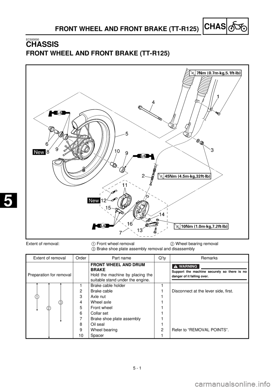
FRONT WHEEL AND FRONT BRAKE (TT-R125)
EC500000
CHASSIS
FRONT WHEEL AND FRONT BRAKE (TT-R125)
Extent of removal:
1
Front wheel removal
2
Wheel bearing removal
3
Brake shoe plate assembly removal and disassembly
Extent of removal Order Part name Q’ty Remarks
Preparation for removal
FRONT WHEEL AND DRUM
BRAKE
Hold the machine by placing the
suitable stand under the engine.
WARNING
Support the machine securely so there is no
danger of it falling over.
1 Brake cable holder 1
2 Brake cable 1 Disconnect at the lever side, first.
3 Axle nut 1
4 Wheel axle 1
5 Front wheel 1
6 Collar set 1
7 Brake shoe plate assembly 1
8 Oil seal 1
9 Wheel bearing 2 Refer to “REMOVAL POINTS”.
10Spacer
1
2
3
1
5
Page 380 of 509
5 - 8
CHAS
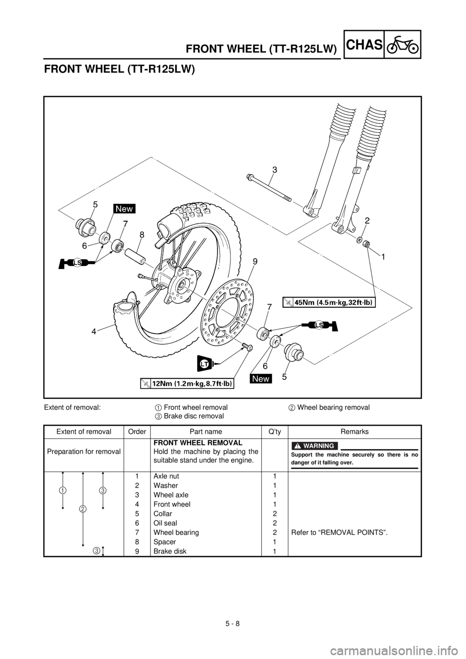
FRONT WHEEL (TT-R125LW)
Extent of removal:1 Front wheel removal2 Wheel bearing removal
3 Brake disc removal
Extent of removal Order Part name Q’ty Remarks
Preparation for removalFRONT WHEEL REMOVAL
Hold the machine by placing the
suitable stand under the engine.
WARNING
Support the machine securely so there is nodanger of it falling over.
1 Axle nut 1
2 Washer 1
3 Wheel axle 1
4 Front wheel 1
5 Collar 2
6 Oil seal 2
7 Wheel bearing 2 Refer to “REMOVAL POINTS”.
8 Spacer 1
9Brake disk
1
2
31
3
FRONT WHEEL (TT-R125LW)
Page 388 of 509
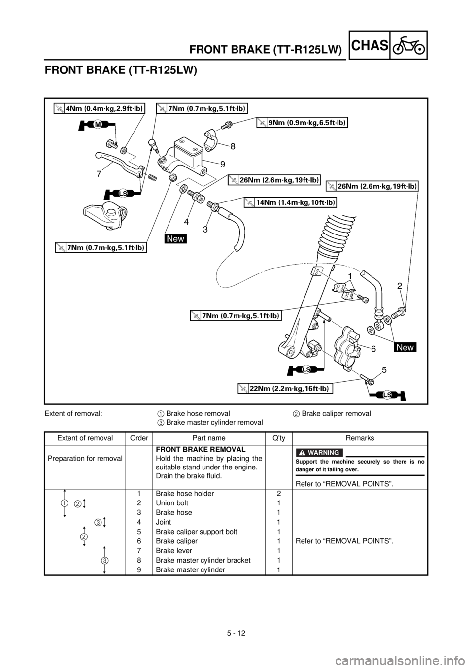
5 - 12
CHAS
FRONT BRAKE (TT-R125LW)
Extent of removal:1 Brake hose removal 2 Brake caliper removal
3 Brake master cylinder removal
Extent of removal Order Part name Q’ty Remarks
Preparation for removalFRONT BRAKE REMOVAL
Hold the machine by placing the
suitable stand under the engine.
Drain the brake fluid.
WARNING
Support the machine securely so there is nodanger of it falling over.
Refer to “REMOVAL POINTS”.
1 Brake hose holder 2
2 Union bolt 1
3 Brake hose 1
4 Joint 1
5 Brake caliper support bolt 1
6 Brake caliper 1 Refer to “REMOVAL POINTS”.
7 Brake lever 1
8 Brake master cylinder bracket 1
9Brake master cylinder
1
3
12
2
3
FRONT BRAKE (TT-R125LW)