seat YAMAHA TTR125 2004 Notices Demploi (in French)
[x] Cancel search | Manufacturer: YAMAHA, Model Year: 2004, Model line: TTR125, Model: YAMAHA TTR125 2004Pages: 610, PDF Size: 25.85 MB
Page 10 of 610
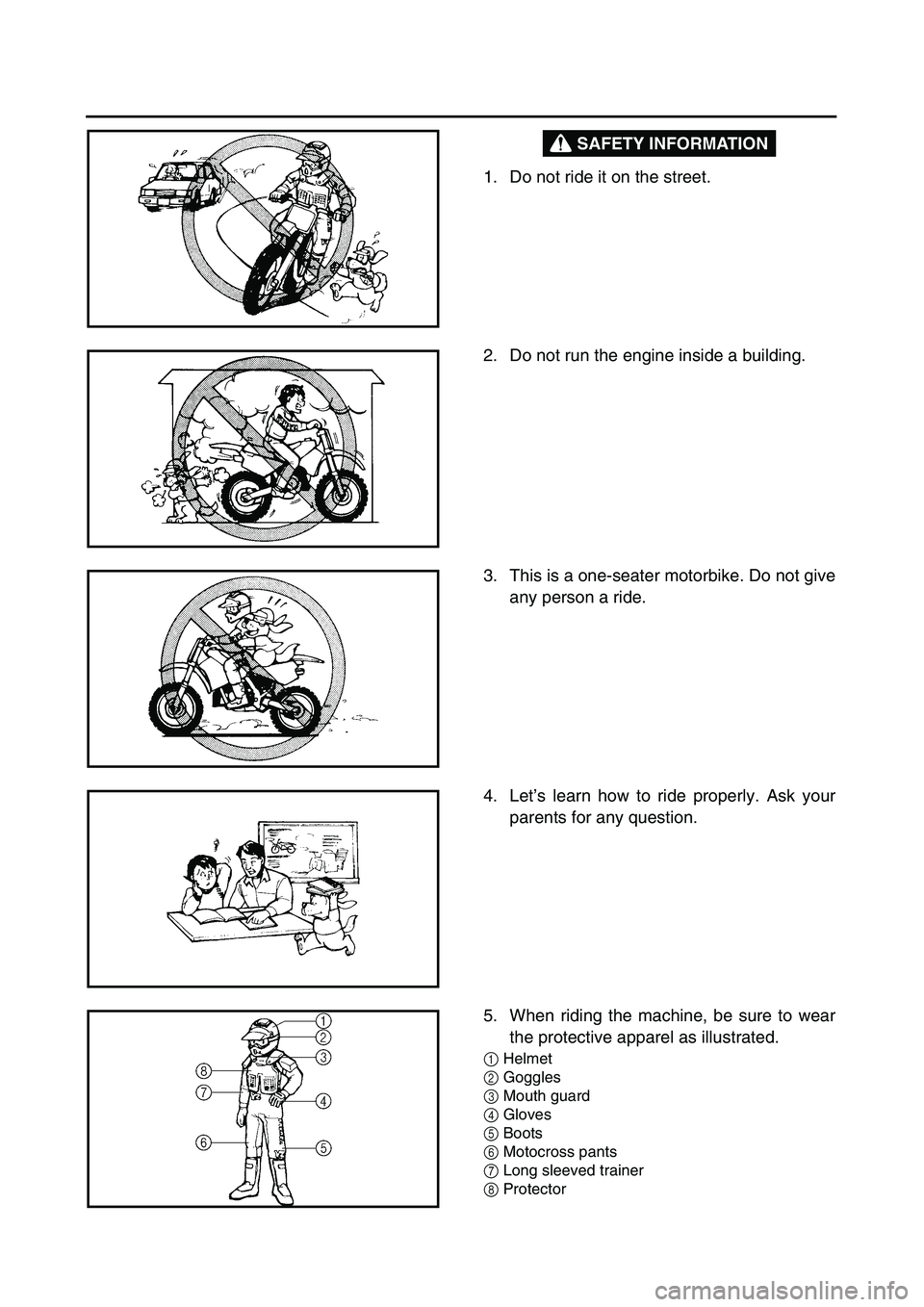
SAFETY INFORMATION
1. Do not ride it on the street.
2. Do not run the engine inside a building.
3. This is a one-seater motorbike. Do not give
any person a ride.
4. Let’s learn how to ride properly. Ask your
parents for any question.
5. When riding the machine, be sure to wear
the protective apparel as illustrated.
1
Helmet
2
Goggles
3
Mouth guard
4
Gloves
5
Boots
6
Motocross pants
7
Long sleeved trainer
8
Protector
Page 26 of 610
CHAPTER 3
REGULAR INSPECTION
AND ADJUSTMENTS
MAINTENANCE INTERVALS ...................3-1
PRE-OPERATION INSPECTION
AND MAINTENANCE ................................3-3
ENGINE ......................................................3-4
CHASSIS .................................................3-15
ELECTRICAL ...........................................3-34
CHAPTER 4
ENGINE
SEAT, FUEL TANK
AND SIDE COVERS ..................................4-1
MUFFLER ..................................................4-2
CARBURETOR ..........................................4-3
CYLINDER HEAD ....................................4-12
CAMSHAFT AND ROCKER ARMS ........4-20
VALVES AND VALVE SPRINGS ............4-24
CYLINDER AND PISTON ........................4-32
CLUTCH AND PRIMARY DRIVEN
GEAR .......................................................4-40
OIL PUMP ................................................4-49
KICK AXLE AND SHIFT SHAFT .............4-53
CDI MAGNETO
(TT-R125/TT-R125LW) ............................4-58
CDI MAGNETO AND STARTER
CLUTCH (TT-R125E/TT-R125LWE) .......4-61
ENGINE REMOVAL .................................4-66
CRANKCASE, CRANKSHAFT
AND BALANCER ....................................4-70
TRANSMISSION, SHIFT CAM
AND SHIFT FORK ...................................4-78
Page 32 of 610
1 - 2
GEN
INFO
MACHINE IDENTIFICATION
EC120001
MACHINE IDENTIFICATION
There are two significant reasons for knowing
the serial number of your machine:
1. When ordering parts, you can give the
number to your Yamaha dealer for positive
identification of the model you own.
2. If your machine is stolen, the authorities
will need the number to search for and
identify your machine.
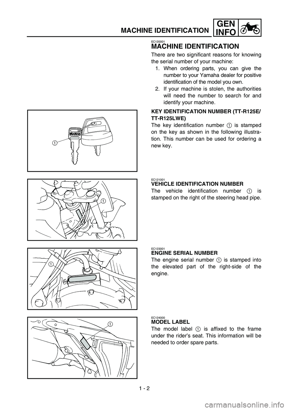
KEY IDENTIFICATION NUMBER (TT-R125E/
TT-R125LWE)
The key identification number 1 is stamped
on the key as shown in the following illustra-
tion. This number can be used for ordering a
new key.
EC121001
VEHICLE IDENTIFICATION NUMBER
The vehicle identification number 1 is
stamped on the right of the steering head pipe.
EC123001
ENGINE SERIAL NUMBER
The engine serial number 1 is stamped into
the elevated part of the right-side of the
engine.
EC124000
MODEL LABEL
The model label 1 is affixed to the frame
under the rider’s seat. This information will be
needed to order spare parts.
Page 64 of 610
1 - 16
GEN
INFO
TORQUE-CHECK POINTS
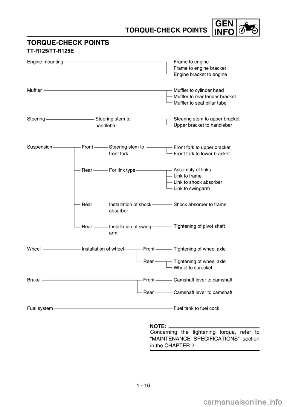
TORQUE-CHECK POINTS
TT-R125/TT-R125E
Engine mounting
Muffler
Steering Steering stem to
handlebar
Suspension Front Steering stem to
front fork
Rear For link type
Rear Installation of shock
absorber
Rear Installation of swing-
arm
Wheel Installation of wheel Front
Rear
Brake Front
Rear
Fuel systemFrame to engine
Frame to engine bracket
Engine bracket to engine
Muffler to cylinder head
Muffler to rear fender bracket
Muffler to seat pillar tube
Steering stem to upper bracket
Upper bracket to handlebar
Front fork to upper bracket
Front fork to lower bracket
Assembly of links
Link to frame
Link to shock absorber
Link to swingarm
Shock absorber to frame
Tightening of pivot shaft
Tightening of wheel axle
Tightening of wheel axle
Wheel to sprocket
Camshaft lever to camshaft
Camshaft lever to camshaft
Fuel tank to fuel cock
NOTE:
Concerning the tightening torque, refer to
“MAINTENANCE SPECIFICATIONS” section
in the CHAPTER 2.
Page 65 of 610
1 - 17
GEN
INFO
TORQUE-CHECK POINTS
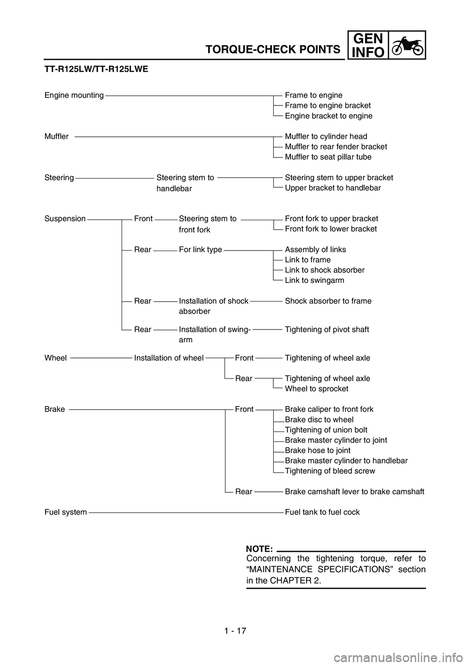
TT-R125LW/TT-R125LWE
Engine mounting
Muffler
Steering Steering stem to
handlebar
Suspension Front Steering stem to
front fork
Rear For link type
Rear Installation of shock
absorber
Rear Installation of swing-
arm
Wheel Installation of wheel Front
Rear
Brake Front
Rear
Fuel systemFrame to engine
Frame to engine bracket
Engine bracket to engine
Muffler to cylinder head
Muffler to rear fender bracket
Muffler to seat pillar tube
Steering stem to upper bracket
Upper bracket to handlebar
Front fork to upper bracket
Front fork to lower bracket
Assembly of links
Link to frame
Link to shock absorber
Link to swingarm
Shock absorber to frame
Tightening of pivot shaft
Tightening of wheel axle
Tightening of wheel axle
Wheel to sprocket
Brake caliper to front fork
Brake disc to wheel
Tightening of union bolt
Brake master cylinder to joint
Brake hose to joint
Brake master cylinder to handlebar
Tightening of bleed screw
Brake camshaft lever to brake camshaft
Fuel tank to fuel cock
NOTE:
Concerning the tightening torque, refer to
“MAINTENANCE SPECIFICATIONS” section
in the CHAPTER 2.
Page 70 of 610
1 - 18
GEN
INFO
CLEANING AND STORAGE
EC1B0000
CLEANING AND STORAGE
EC1B1000
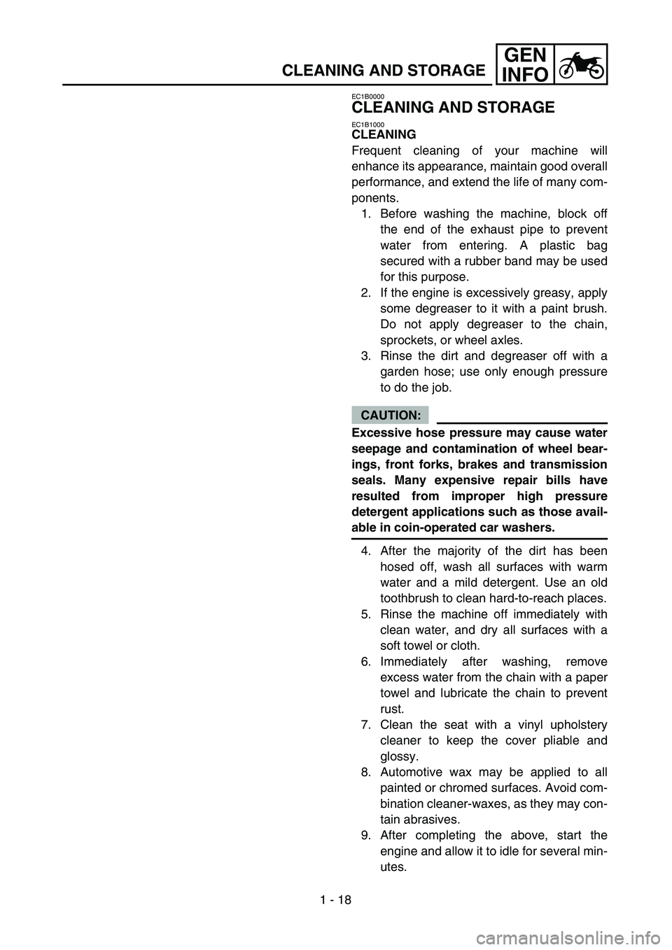
CLEANING
Frequent cleaning of your machine will
enhance its appearance, maintain good overall
performance, and extend the life of many com-
ponents.
1. Before washing the machine, block off
the end of the exhaust pipe to prevent
water from entering. A plastic bag
secured with a rubber band may be used
for this purpose.
2. If the engine is excessively greasy, apply
some degreaser to it with a paint brush.
Do not apply degreaser to the chain,
sprockets, or wheel axles.
3. Rinse the dirt and degreaser off with a
garden hose; use only enough pressure
to do the job.
CAUTION:
Excessive hose pressure may cause water
seepage and contamination of wheel bear-
ings, front forks, brakes and transmission
seals. Many expensive repair bills have
resulted from improper high pressure
detergent applications such as those avail-
able in coin-operated car washers.
4. After the majority of the dirt has been
hosed off, wash all surfaces with warm
water and a mild detergent. Use an old
toothbrush to clean hard-to-reach places.
5. Rinse the machine off immediately with
clean water, and dry all surfaces with a
soft towel or cloth.
6. Immediately after washing, remove
excess water from the chain with a paper
towel and lubricate the chain to prevent
rust.
7. Clean the seat with a vinyl upholstery
cleaner to keep the cover pliable and
glossy.
8. Automotive wax may be applied to all
painted or chromed surfaces. Avoid com-
bination cleaner-waxes, as they may con-
tain abrasives.
9. After completing the above, start the
engine and allow it to idle for several min-
utes.
Page 72 of 610
1 - 19
GEN
INFO
CLEANING AND STORAGE
EC182001
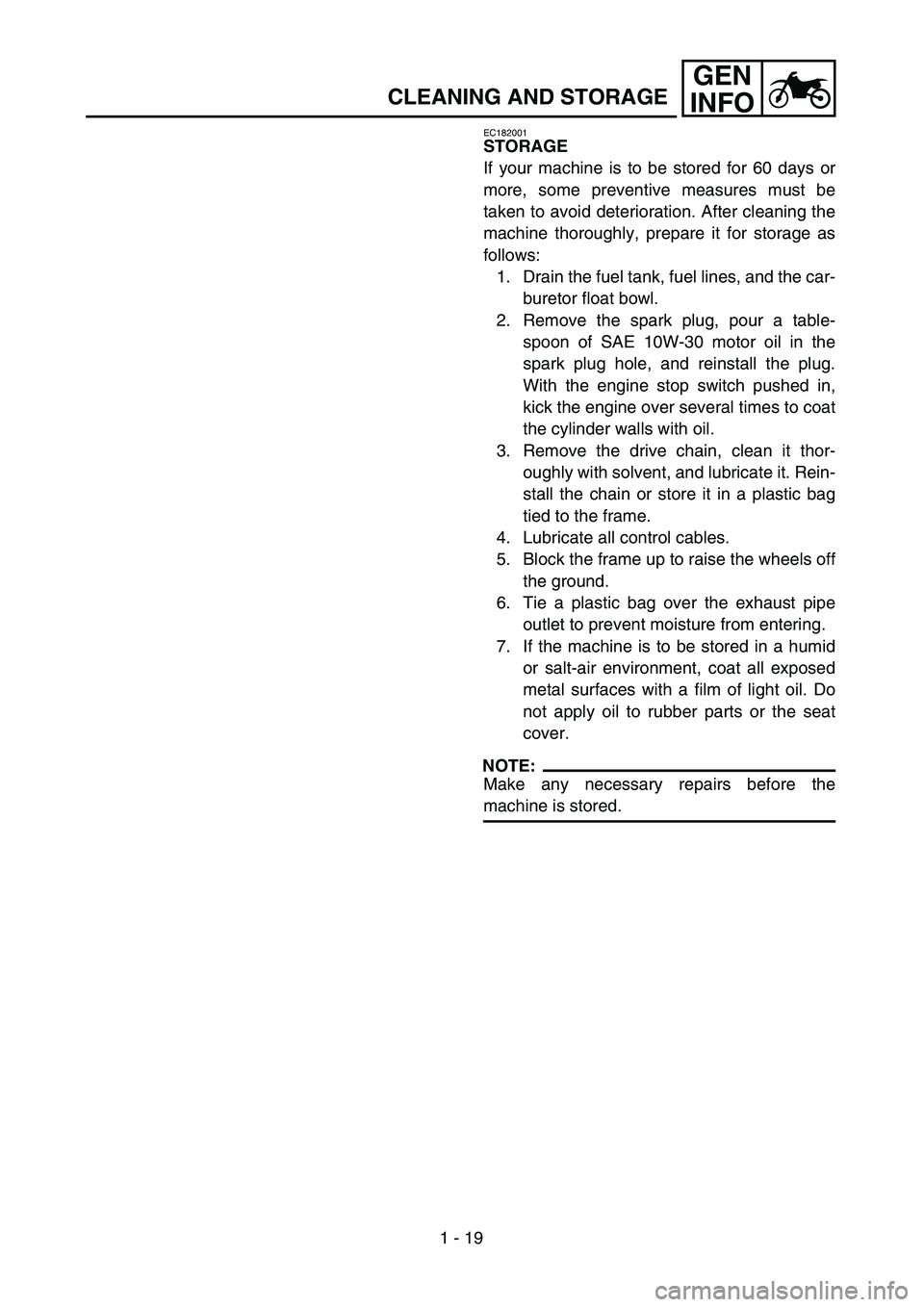
STORAGE
If your machine is to be stored for 60 days or
more, some preventive measures must be
taken to avoid deterioration. After cleaning the
machine thoroughly, prepare it for storage as
follows:
1. Drain the fuel tank, fuel lines, and the car-
buretor float bowl.
2. Remove the spark plug, pour a table-
spoon of SAE 10W-30 motor oil in the
spark plug hole, and reinstall the plug.
With the engine stop switch pushed in,
kick the engine over several times to coat
the cylinder walls with oil.
3. Remove the drive chain, clean it thor-
oughly with solvent, and lubricate it. Rein-
stall the chain or store it in a plastic bag
tied to the frame.
4. Lubricate all control cables.
5. Block the frame up to raise the wheels off
the ground.
6. Tie a plastic bag over the exhaust pipe
outlet to prevent moisture from entering.
7. If the machine is to be stored in a humid
or salt-air environment, coat all exposed
metal surfaces with a film of light oil. Do
not apply oil to rubber parts or the seat
cover.
NOTE:
Make any necessary repairs before the
machine is stored.
Page 74 of 610
SPEC
2 - 1
GENERAL SPECIFICATIONS
EC200000
SPECIFICATIONS
EC211000
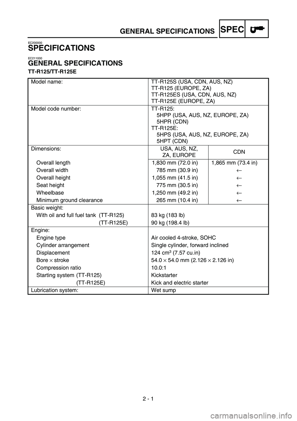
GENERAL SPECIFICATIONS
TT-R125/TT-R125E
Model name: TT-R125S (USA, CDN, AUS, NZ)
TT-R125 (EUROPE, ZA)
TT-R125ES (USA, CDN, AUS, NZ)
TT-R125E (EUROPE, ZA)
Model code number: TT-R125:
5HPP (USA, AUS, NZ, EUROPE, ZA)
5HPR (CDN)
TT-R125E:
5HPS (USA, AUS, NZ, EUROPE, ZA)
5HPT (CDN)
Dimensions: USA, AUS, NZ,
ZA, EUROPECDN
Overall length 1,830 mm (72.0 in) 1,865 mm (73.4 in)
Overall width 785 mm (30.9 in)←
Overall height 1,055 mm (41.5 in)←
Seat height 775 mm (30.5 in)←
Wheelbase 1,250 mm (49.2 in)←
Minimum ground clearance 265 mm (10.4 in)←
Basic weight:
With oil and full fuel tank (TT-R125) 83 kg (183 lb)
(TT-R125E) 90 kg (198.4 lb)
Engine:
Engine type Air cooled 4-stroke, SOHC
Cylinder arrangement Single cylinder, forward inclined
Displacement 124 cm
3 (7.57 cu.in)
Bore × stroke 54.0 × 54.0 mm (2.126 × 2.126 in)
Compression ratio 10.0:1
Starting system (TT-R125) Kickstarter
(TT-R125E) Kick and electric starter
Lubrication system: Wet sump
Page 77 of 610
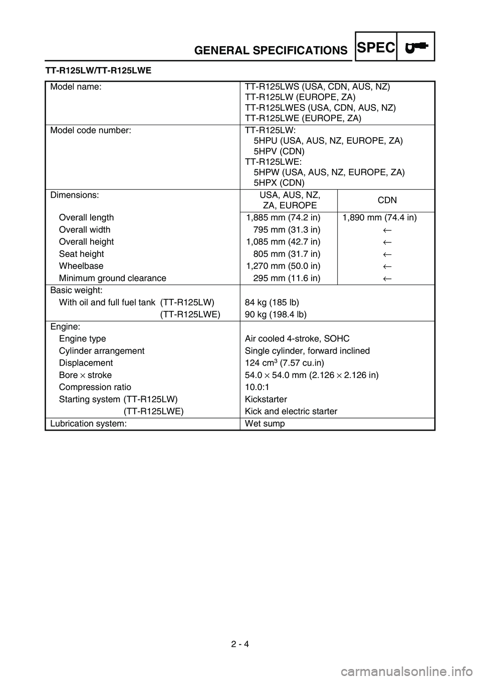
SPEC
2 - 4
GENERAL SPECIFICATIONS
TT-R125LW/TT-R125LWE
Model name: TT-R125LWS (USA, CDN, AUS, NZ)
TT-R125LW (EUROPE, ZA)
TT-R125LWES (USA, CDN, AUS, NZ)
TT-R125LWE (EUROPE, ZA)
Model code number: TT-R125LW:
5HPU (USA, AUS, NZ, EUROPE, ZA)
5HPV (CDN)
TT-R125LWE:
5HPW (USA, AUS, NZ, EUROPE, ZA)
5HPX (CDN)
Dimensions: USA, AUS, NZ,
ZA, EUROPECDN
Overall length 1,885 mm (74.2 in) 1,890 mm (74.4 in)
Overall width 795 mm (31.3 in)←
Overall height 1,085 mm (42.7 in)←
Seat height 805 mm (31.7 in)←
Wheelbase 1,270 mm (50.0 in)←
Minimum ground clearance 295 mm (11.6 in)←
Basic weight:
With oil and full fuel tank (TT-R125LW) 84 kg (185 lb)
(TT-R125LWE) 90 kg (198.4 lb)
Engine:
Engine type Air cooled 4-stroke, SOHC
Cylinder arrangement Single cylinder, forward inclined
Displacement 124 cm
3 (7.57 cu.in)
Bore × stroke 54.0 × 54.0 mm (2.126 × 2.126 in)
Compression ratio 10.0:1
Starting system (TT-R125LW) Kickstarter
(TT-R125LWE) Kick and electric starter
Lubrication system: Wet sump
Page 81 of 610
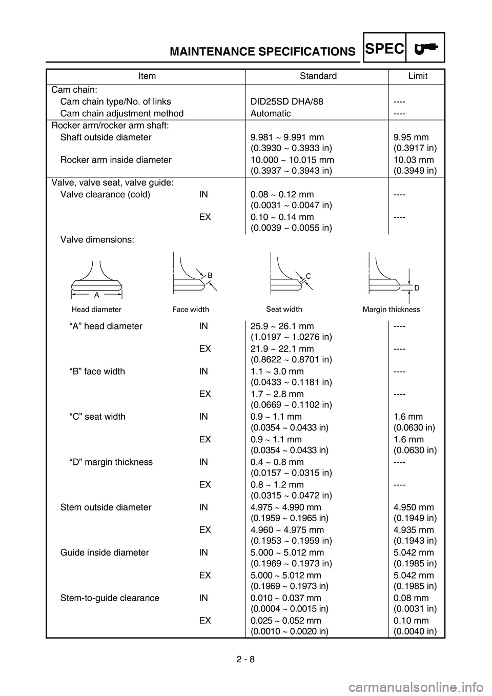
SPEC
2 - 8
MAINTENANCE SPECIFICATIONS
Cam chain:
Cam chain type/No. of links DID25SD DHA/88 ----
Cam chain adjustment method Automatic ----
Rocker arm/rocker arm shaft:
Shaft outside diameter 9.981 ~ 9.991 mm
(0.3930 ~ 0.3933 in)9.95 mm
(0.3917 in)
Rocker arm inside diameter 10.000 ~ 10.015 mm
(0.3937 ~ 0.3943 in)10.03 mm
(0.3949 in)
Valve, valve seat, valve guide:
Valve clearance (cold) IN 0.08 ~ 0.12 mm
(0.0031 ~ 0.0047 in)----
EX 0.10 ~ 0.14 mm
(0.0039 ~ 0.0055 in)----
Valve dimensions:
“A” head diameter IN 25.9 ~ 26.1 mm
(1.0197 ~ 1.0276 in)----
EX 21.9 ~ 22.1 mm
(0.8622 ~ 0.8701 in)----
“B” face width IN 1.1 ~ 3.0 mm
(0.0433 ~ 0.1181 in)----
EX 1.7 ~ 2.8 mm
(0.0669 ~ 0.1102 in)----
“C” seat width IN0.9 ~ 1.1 mm
(0.0354 ~ 0.0433 in)1.6 mm
(0.0630 in)
EX 0.9 ~ 1.1 mm
(0.0354 ~ 0.0433 in)1.6 mm
(0.0630 in)
“D” margin thickness IN 0.4 ~ 0.8 mm
(0.0157 ~ 0.0315 in)----
EX 0.8 ~ 1.2 mm
(0.0315 ~ 0.0472 in)----
Stem outside diameter IN4.975 ~ 4.990 mm
(0.1959 ~ 0.1965 in)4.950 mm
(0.1949 in)
EX 4.960 ~ 4.975 mm
(0.1953 ~ 0.1959 in)4.935 mm
(0.1943 in)
Guide inside diameter IN 5.000 ~ 5.012 mm
(0.1969 ~ 0.1973 in)5.042 mm
(0.1985 in)
EX 5.000 ~ 5.012 mm
(0.1969 ~ 0.1973 in)5.042 mm
(0.1985 in)
Stem-to-guide clearance IN0.010 ~ 0.037 mm
(0.0004 ~ 0.0015 in)0.08 mm
(0.0031 in)
EX 0.025 ~ 0.052 mm
(0.0010 ~ 0.0020 in)0.10 mm
(0.0040 in) Item Standard Limit
Head diameter
B
Face widthC
Seat width
D
Margin thicknessA