maintenance YAMAHA TTR50 2006 Betriebsanleitungen (in German)
[x] Cancel search | Manufacturer: YAMAHA, Model Year: 2006, Model line: TTR50, Model: YAMAHA TTR50 2006Pages: 390, PDF-Größe: 9.69 MB
Page 4 of 390
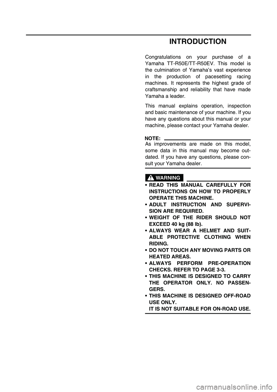
INTRODUCTION
Congratulations on your purchase of a
Yamaha TT-R50E/TT-R50EV. This model is
the culmination of Yamaha’s vast experience
in the production of pacesetting racing
machines. It represents the highest grade of
craftsmanship and reliability that have made
Yamaha a leader.
This manual explains operation, inspection
and basic maintenance of your machine. If you
have any questions about this manual or your
machine, please contact your Yamaha dealer.
NOTE:
As improvements are made on this model,
some data in this manual may become out-
dated. If you have any questions, please con-
sult your Yamaha dealer.
WARNING
READ THIS MANUAL CAREFULLY FOR
INSTRUCTIONS ON HOW TO PROPERLY
OPERATE THIS MACHINE.
ADULT INSTRUCTION AND SUPERVI-
SION ARE REQUIRED.
WEIGHT OF THE RIDER SHOULD NOT
EXCEED 40 kg (88 lb).
ALWAYS WEAR A HELMET AND SUIT-
ABLE PROTECTIVE CLOTHING WHEN
RIDING.
DO NOT TOUCH ANY MOVING PARTS OR
HEATED AREAS.
ALWAYS PERFORM PRE-OPERATION
CHECKS. REFER TO PAGE 3-3.
THIS MACHINE IS DESIGNED TO CARRY
THE OPERATOR ONLY. NO PASSEN-
GERS.
THIS MACHINE IS DESIGNED OFF-ROAD
USE ONLY.
IT IS NOT SUITABLE FOR ON-ROAD USE.
Page 22 of 390
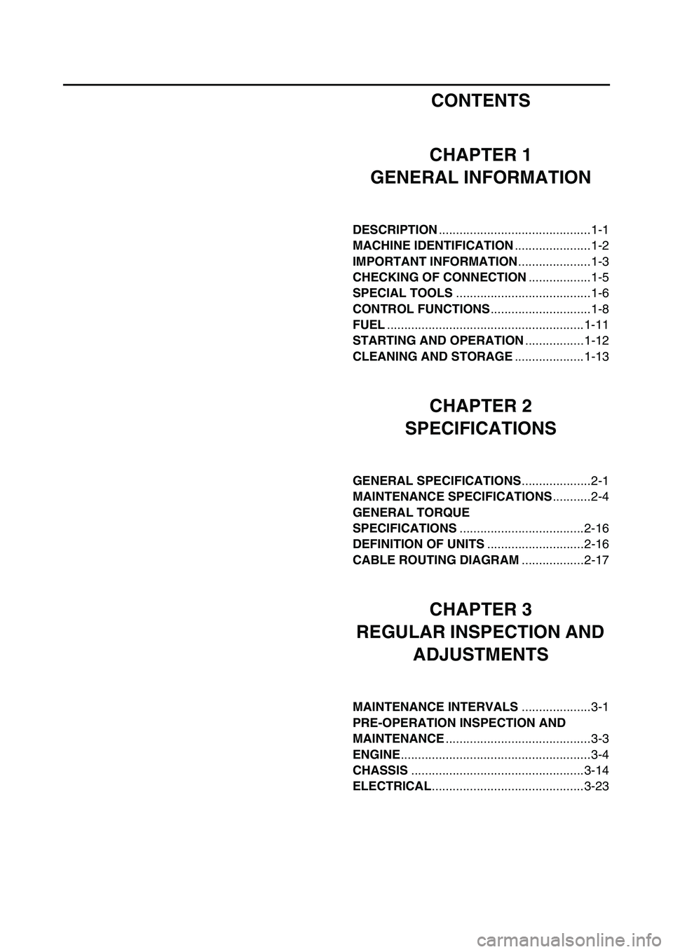
CONTENTS
CHAPTER 1
GENERAL INFORMATION
DESCRIPTION ............................................1-1
MACHINE IDENTIFICATION ......................1-2
IMPORTANT INFORMATION .....................1-3
CHECKING OF CONNECTION ..................1-5
SPECIAL TOOLS .......................................1-6
CONTROL FUNCTIONS .............................1-8
FUEL .........................................................1-11
STARTING AND OPERATION .................1-12
CLEANING AND STORAGE ....................1-13
CHAPTER 2
SPECIFICATIONS
GENERAL SPECIFICATIONS ....................2-1
MAINTENANCE SPECIFICATIONS ...........2-4
GENERAL TORQUE
SPECIFICATIONS ....................................2-16
DEFINITION OF UNITS ............................2-16
CABLE ROUTING DIAGRAM ..................2-17
CHAPTER 3
REGULAR INSPECTION AND ADJUSTMENTS
MAINTENANCE INTERVALS ....................3-1
PRE-OPERATION INSPECTION AND
MAINTENANCE ..........................................3-3
ENGINE .......................................................3-4
CHASSIS ..................................................3-14
ELECTRICAL ............................................3-23
Page 24 of 390
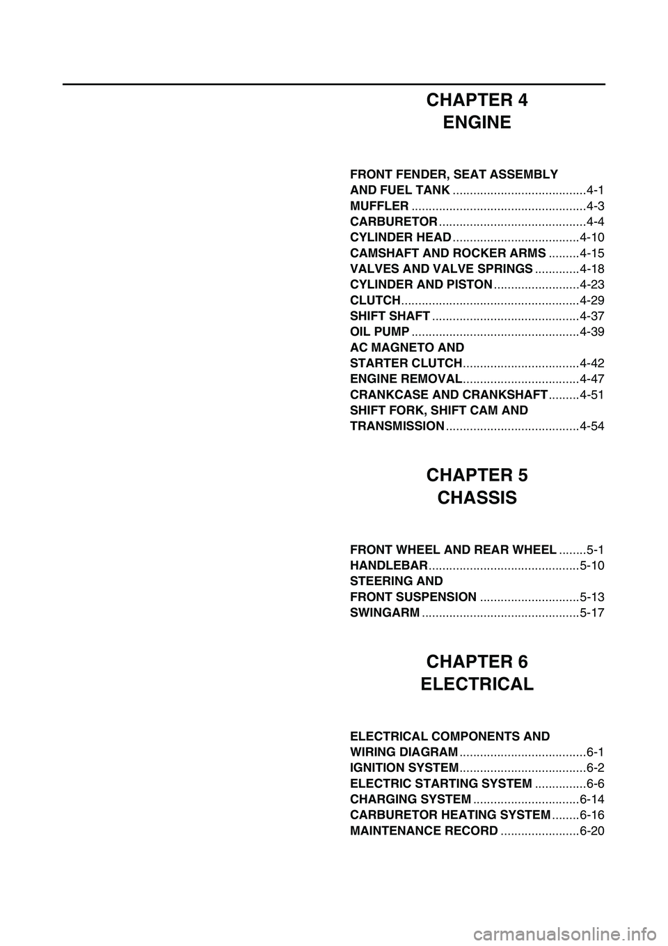
CHAPTER 4ENGINE
FRONT FENDER, SEAT ASSEMBLY
AND FUEL TANK .......................................4-1
MUFFLER ...................................................4-3
CARBURETOR ...........................................4-4
CYLINDER HEAD .....................................4-10
CAMSHAFT AND ROCKER ARMS .........4-15
VALVES AND VALVE SPRINGS .............4-18
CYLINDER AND PISTON .........................4-23
CLUTCH ....................................................4-29
SHIFT SHAFT ...........................................4-37
OIL PUMP .................................................4-39
AC MAGNETO AND
STARTER CLUTCH ..................................4-42
ENGINE REMOVAL ..................................4-47
CRANKCASE AND CRANKSHAFT .........4-51
SHIFT FORK, SHIFT CAM AND
TRANSMISSION .......................................4-54
CHAPTER 5
CHASSIS
FRONT WHEEL AND REAR WHEEL ........5-1
HANDLEBAR ............................................5-10
STEERING AND
FRONT SUSPENSION .............................5-13
SWINGARM ..............................................5-17
CHAPTER 6
ELECTRICAL
ELECTRICAL COMPONENTS AND
WIRING DIAGRAM .....................................6-1
IGNITION SYSTEM .....................................6-2
ELECTRIC STARTING SYSTEM ...............6-6
CHARGING SYSTEM ...............................6-14
CARBURETOR HEATING SYSTEM ........6-16
MAINTENANCE RECORD .......................6-20
Page 59 of 390
SPEC
2 - 4
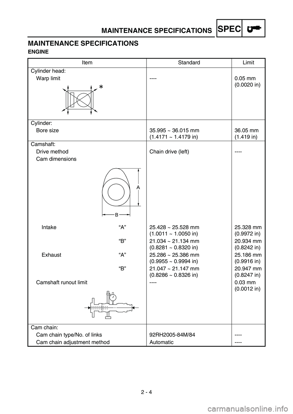
MAINTENANCE SPECIFICATIONS
ENGINEItem Standard Limit
Cylinder head: Warp limit ---- 0.05 mm (0.0020 in)
Cylinder: Bore size 35.995 ~ 36.015 mm (1.4171 ~ 1.4179 in)36.05 mm
(1.419 in)
Camshaft: Drive method Chain drive (left) ----
Cam dimensions
Intake “A ” 25.428 ~ 25.528 mm
(1.0011 ~ 1.0050 in) 25.328 mm
(0.9972 in)
“ B ” 21.034 ~ 21.134 mm
(0.8281 ~ 0.8320 in) 20.934 mm
(0.8242 in)
Exhaust “A ” 25.286 ~ 25.386 mm
(0.9955 ~ 0.9994 in) 25.186 mm
(0.9916 in)
“ B ” 21.047 ~ 21.147 mm
(0.8286 ~ 0.8326 in) 20.947 mm
(0.8247 in)
Camshaft runout limit ---- 0.03 mm (0.0012 in)
Cam chain: Cam chain type/No. of links 92RH2005-84M/84 ----
Cam chain adjustment method Automatic ----
MAINTENANCE SPECIFICATIONS
Page 60 of 390

SPEC
2 - 5
Rocker arm/rocker arm shaft:
Shaft outside diameter 9.981 ~ 9.991 mm (0.3930 ~ 0.3933 in)9.976 mm
(0.3928 in)
Rocker arm inside diameter 10.000 ~ 10.015 mm (0.3937 ~ 0.3943 in)10.025 mm
(0.3947 in)
Valve, valve seat, valve guide: Valve clearance (cold) IN 0.05 ~ 0.09 mm (0.0020 ~ 0.0035 in)----
EX 0.08 ~ 0.12 mm (0.0031 ~ 0.0047 in) ----
Valve dimensions:
“A ” head diameter IN 16.90 ~ 17.10 mm
(0.6653 ~ 0.6732 in)----
EX 14.40 ~ 14.60 mm (0.5669 ~ 0.5748 in) ----
“ B ” face width IN 1.05 ~ 1.55 mm
(0.0413 ~ 0.0610 in)----
EX 1.05 ~ 1.55 mm (0.0413 ~ 0.0610 in) ----
“ C ” seat width IN 0.9 ~ 1.1 mm
(0.0354 ~ 0.0433 in)1.6 mm
(0.0630 in)
EX 0.9 ~ 1.1 mm (0.0354 ~ 0.0433 in) 1.6 mm
(0.0630 in)
“ D ” margin thickness IN 0.5 ~ 0.9 mm
(0.0197 ~ 0.354 in)----
EX 0.5 ~ 0.9 mm (0.0197 ~ 0.0354 in) ----
Stem outside diameter IN 4.475 ~ 4.490 mm (0.1762 ~ 0.1768 in)4.445 mm
(0.1750 in)
EX 4.460 ~ 4.475 mm (0.1756 ~ 0.1762 in) 4.430 mm
(0.1744 in)
Guide inside diameter IN 4.500 ~ 4.512 mm (0.1772 ~ 0.1776 in)4.550 mm
(0.1791 in)
EX 4.500 ~ 4.512 mm (0.1772 ~ 0.1776 in) 4.550 mm
(0.1791 in)
Stem-to-guide clearance IN 0.010 ~ 0.037 mm (0.0004 ~ 0.0015 in)0.08 mm
(0.0031 in)
EX 0.025 ~ 0.052 mm (0.0010 ~ 0.0020 in) 0.10 mm
(0.0039 in)
Item Standard Limit
BC
DA
Head diameter Face width Seat width Margin thickness
MAINTENANCE SPECIFICATIONS
Page 61 of 390
SPEC
2 - 6
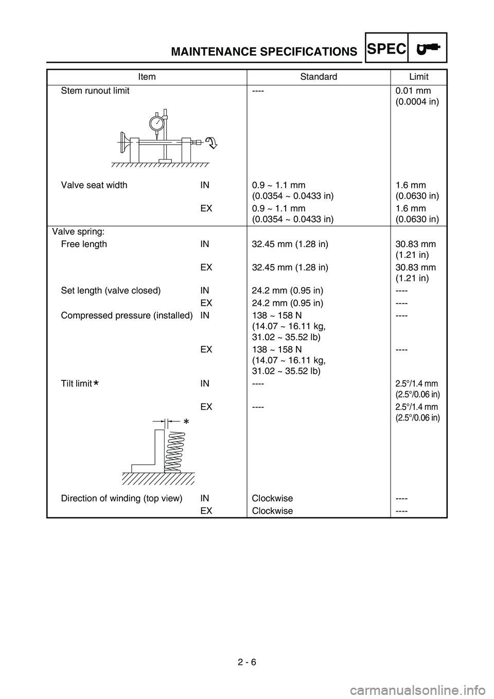
Stem runout limit ---- 0.01 mm
(0.0004 in)
Valve seat width IN 0.9 ~ 1.1 mm (0.0354 ~ 0.0433 in)1.6 mm
(0.0630 in)
EX 0.9 ~ 1.1 mm (0.0354 ~ 0.0433 in) 1.6 mm
(0.0630 in)
Valve spring: Free length IN 32.45 mm (1.28 in) 30.83 mm (1.21 in)
EX 32.45 mm (1.28 in) 30.83 mm (1.21 in)
Set length (valve closed) IN 24.2 mm (0.95 in) ---- EX 24.2 mm (0.95 in) ----
Compressed pressure (installed) IN 138 ~ 158 N (14.07 ~ 16.11 kg,
31.02 ~ 35.52 lb)----
EX 138 ~ 158 N (14.07 ~ 16.11 kg,
31.02 ~ 35.52 lb) ----
Tilt limit IN ----
2.5 °/1.4 mm
(2.5 °/0.06 in)
EX ----2.5 °/1.4 mm
(2.5 °/0.06 in)
Direction of winding (top view) IN Clockwise ----
EX Clockwise ----
Item Standard Limit
*
MAINTENANCE SPECIFICATIONS
Page 62 of 390
SPEC
2 - 7
Piston:
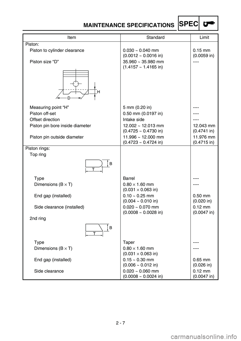
Piston to cylinder clearance 0.030 ~ 0.040 mm (0.0012 ~ 0.0016 in)0.15 mm
(0.0059 in)
Piston size “D ” 35.960 ~ 35.980 mm
(1.4157 ~ 1.4165 in) ----
Measuring point “H ” 5 mm (0.20 in) ----
Piston off-set 0.50 mm (0.0197 in) ----
Offset direction Intake side ----
Piston pin bore inside diameter 12.002 ~ 12.013 mm (0.4725 ~ 0.4730 in)12.043 mm
(0.4741 in)
Piston pin outside diameter 11.996 ~ 12.000 mm (0.4723 ~ 0.4724 in)11.976 mm
(0.4715 in)
Piston rings: Top ring
Type Barrel ----
Dimensions (B × T) 0.80 × 1.60 mm
(0.031 × 0.063 in) ----
End gap (installed) 0.10 ~ 0.25 mm (0.004 ~ 0.010 in)0.50 mm
(0.020 in)
Side clearance (installed) 0.020 ~ 0.070 mm (0.0008 ~ 0.0028 in)0.12 mm
(0.0047 in)
2nd ring
Type Taper ----
Dimensions (B × T) 0.80 × 1.60 mm
(0.031 × 0.063 in) ----
End gap (installed) 0.15 ~ 0.30 mm (0.006 ~ 0.012 in)0.65 mm
(0.026 in)
Side clearance 0.020 ~ 0.060 mm (0.0008 ~ 0.0024 in)0.12 mm
(0.0047 in)
Item Standard Limit
H
D
T
B
B
T
MAINTENANCE SPECIFICATIONS
Page 63 of 390
SPEC
2 - 8
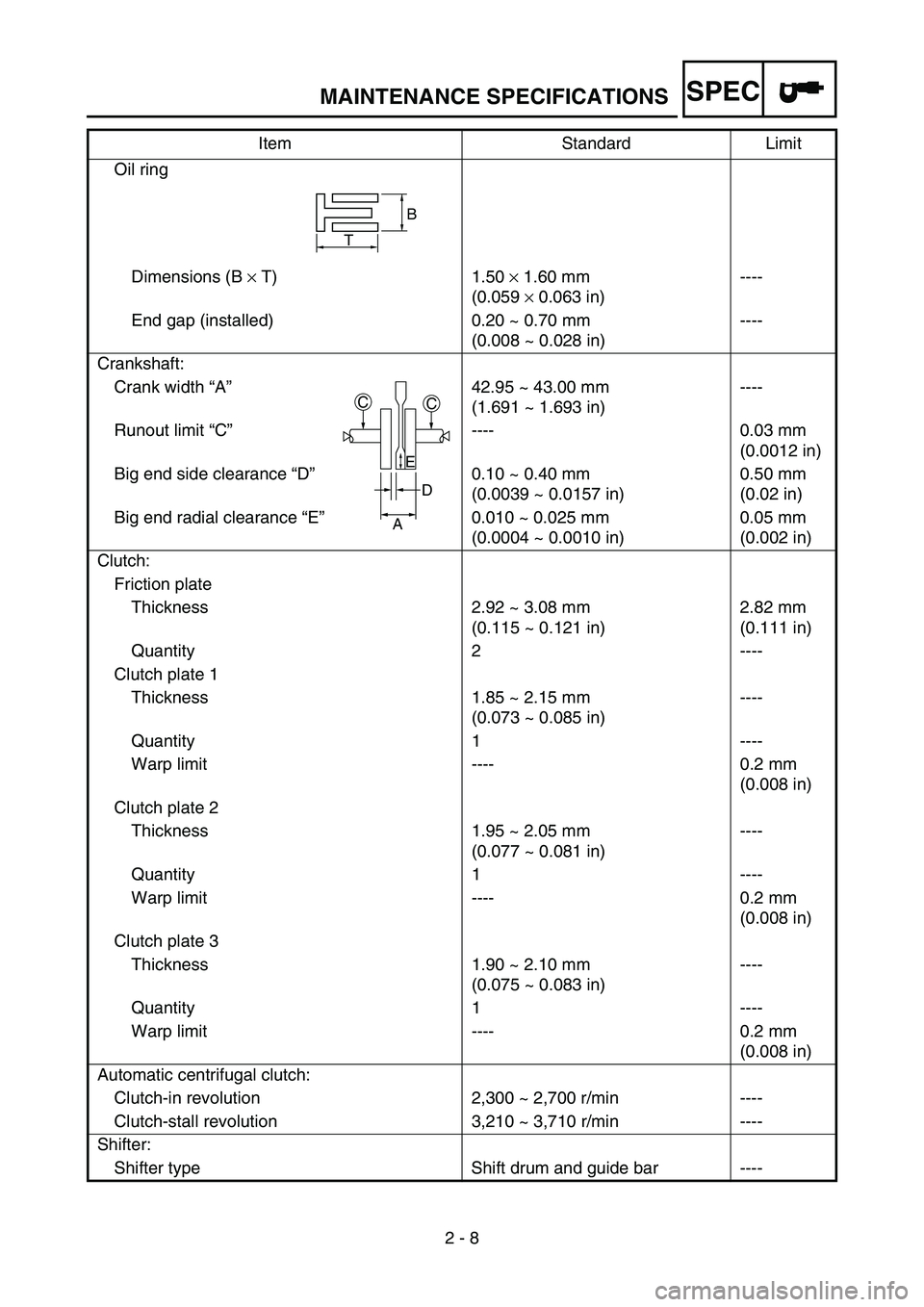
Oil ring
Dimensions (B × T) 1.50 × 1.60 mm
(0.059 × 0.063 in) ----
End gap (installed) 0.20 ~ 0.70 mm (0.008 ~ 0.028 in)----
Crankshaft: Crank width “A” 42.95 ~ 43.00 mm (1.691 ~ 1.693 in)----
Runout limit “C” ---- 0.03 mm (0.0012 in)
Big end side clearance “D” 0.10 ~ 0.40 mm (0.0039 ~ 0.0157 in)0.50 mm
(0.02 in)
Big end radial clearance “E” 0.010 ~ 0.025 mm (0.0004 ~ 0.0010 in)0.05 mm
(0.002 in)
Clutch: Friction plate Thickness 2.92 ~ 3.08 mm (0.115 ~ 0.121 in)2.82 mm
(0.111 in)
Quantity 2 ----
Clutch plate 1 Thickness 1.85 ~ 2.15 mm (0.073 ~ 0.085 in)----
Quantity 1 ----
Warp limit ---- 0.2 mm (0.008 in)
Clutch plate 2 Thickness 1.95 ~ 2.05 mm (0.077 ~ 0.081 in)----
Quantity 1 ----
Warp limit ---- 0.2 mm (0.008 in)
Clutch plate 3 Thickness 1.90 ~ 2.10 mm (0.075 ~ 0.083 in)----
Quantity 1 ----
Warp limit ---- 0.2 mm (0.008 in)
Automatic centrifugal clutch: Clutch-in revolution 2,300 ~ 2,700 r/min ----
Clutch-stall revolution 3,210 ~ 3,710 r/min ----
Shifter: Shifter type Shift drum and guide bar ---- Item Standard Limit
B
T
CC
D
A
E
MAINTENANCE SPECIFICATIONS
Page 64 of 390
SPEC
2 - 9
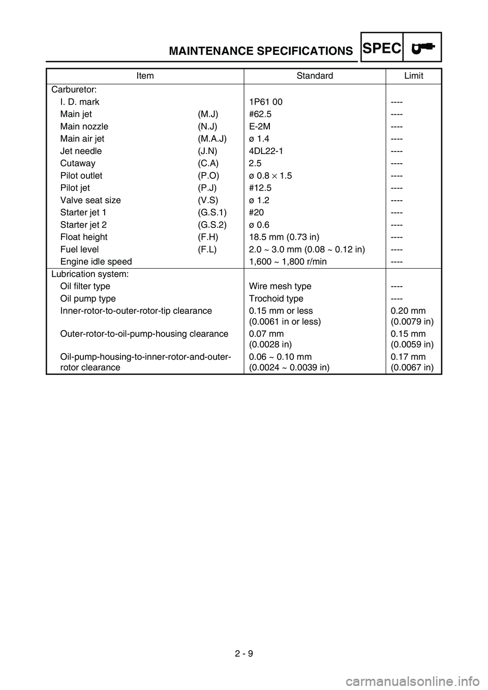
Carburetor:
I. D. mark 1P61 00 ----
Main jet (M.J) #62.5 ----
Main nozzle (N.J) E-2M ----
Main air jet (M.A.J) ø 1.4 ----
Jet needle (J.N) 4DL22-1 ----
Cutaway (C.A) 2.5 ----
Pilot outlet (P.O) ø 0.8 × 1.5 ----
Pilot jet (P.J) #12.5 ----
Valve seat size (V.S) ø 1.2 ----
Starter jet 1 (G.S.1) #20 ----
Starter jet 2 (G.S.2) ø 0.6 ----
Float height (F.H) 18.5 mm (0.73 in) ----
Fuel level (F.L) 2.0 ~ 3.0 mm (0.08 ~ 0.12 in) ----
Engine idle speed 1,600 ~ 1,800 r/min ----
Lubrication system: Oil filter type Wire mesh type ----
Oil pump type Trochoid type ----
Inner-rotor-to-outer-rotor-tip clearance 0.15 mm or less (0.0061 in or less)0.20 mm
(0.0079 in)
Outer-rotor-to-oil-pump-housing clearance 0.07 mm (0.0028 in)0.15 mm
(0.0059 in)
Oil-pump-housing-to-inner-rotor-and-outer-
rotor clearance 0.06 ~ 0.10 mm
(0.0024 ~ 0.0039 in)0.17 mm
(0.0067 in)
Item Standard Limit
MAINTENANCE SPECIFICATIONS
Page 65 of 390
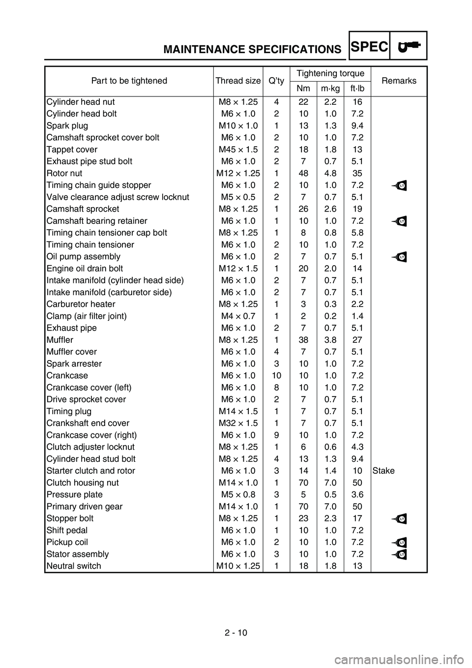
SPEC
2 - 10
Part to be tightened Thread size Q
’ty Tightening torque
Remarks
Nm m ·kg ft ·lb
Cylinder head nut M8 × 1.25 4 22 2.2 16
Cylinder head bolt M6 × 1.0 2 10 1.0 7.2
Spark plug M10 × 1.0 1 13 1.3 9.4
Camshaft sprocket cover bolt M6 × 1.0 2 10 1.0 7.2
Tappet cover M45 × 1.5 2 18 1.8 13
Exhaust pipe stud bolt M6 × 1.0 2 7 0.7 5.1
Rotor nut M12 × 1.25 1 48 4.8 35
Timing chain guide stopper M6 × 1.0 2 10 1.0 7.2
LT
Valve clearance adjust screw locknut M5 × 0.5 2 7 0.7 5.1
Camshaft sprocket M8 × 1.25 1 26 2.6 19
Camshaft bearing retainer M6 × 1.0 1 10 1.0 7.2
LT
Timing chain tensioner cap bolt M8 × 1.25 1 8 0.8 5.8
Timing chain tensioner M6 × 1.0 2 10 1.0 7.2
Oil pump assembly M6 × 1.0 2 7 0.7 5.1
LT
Engine oil drain bolt M12 × 1.5 1 20 2.0 14
Intake manifold (cylinder head side) M6 × 1.0 2 7 0.7 5.1
Intake manifold (carburetor side) M6 × 1.0 2 7 0.7 5.1
Carburetor heater M8 × 1.25 1 3 0.3 2.2
Clamp (air filter joint) M4 × 0.7 1 2 0.2 1.4
Exhaust pipe M6 × 1.0 2 7 0.7 5.1
Muffler M8 × 1.25 1 38 3.8 27
Muffler cover M6 × 1.0 4 7 0.7 5.1
Spark arrester M6 × 1.0 3 10 1.0 7.2
Crankcase M6 × 1.0 10 10 1.0 7.2
Crankcase cover (left) M6 × 1.0 8 10 1.0 7.2
Drive sprocket cover M6 × 1.0 2 7 0.7 5.1
Timing plug M14 × 1.5 1 7 0.7 5.1
Crankshaft end cover M32 × 1.5 1 7 0.7 5.1
Crankcase cover (right) M6 × 1.0 9 10 1.0 7.2
Clutch adjuster locknut M8 × 1.25 1 6 0.6 4.3
Cylinder head stud bolt M8 × 1.25 4 13 1.3 9.4
Starter clutch and rotor M6 × 1.0 3 14 1.4 10 Stake
Clutch housing nut M14 × 1.0 1 70 7.0 50
Pressure plate M5 × 0.8 3 5 0.5 3.6
Primary driven gear M14 × 1.0 1 70 7.0 50
Stopper bolt M8 × 1.25 1 23 2.3 17
LT
Shift pedal M6 × 1.0 1 10 1.0 7.2
Pickup coil M6 × 1.0 2 10 1.0 7.2
LT
Stator assembly M6 × 1.0 3 10 1.0 7.2LT
Neutral switch M10 × 1.25 1 18 1.8 13
MAINTENANCE SPECIFICATIONS