clock YAMAHA TTR50 2006 Owners Manual
[x] Cancel search | Manufacturer: YAMAHA, Model Year: 2006, Model line: TTR50, Model: YAMAHA TTR50 2006Pages: 390, PDF Size: 9.69 MB
Page 46 of 390

1 - 10
GEN
INFO
CONTROL FUNCTIONS
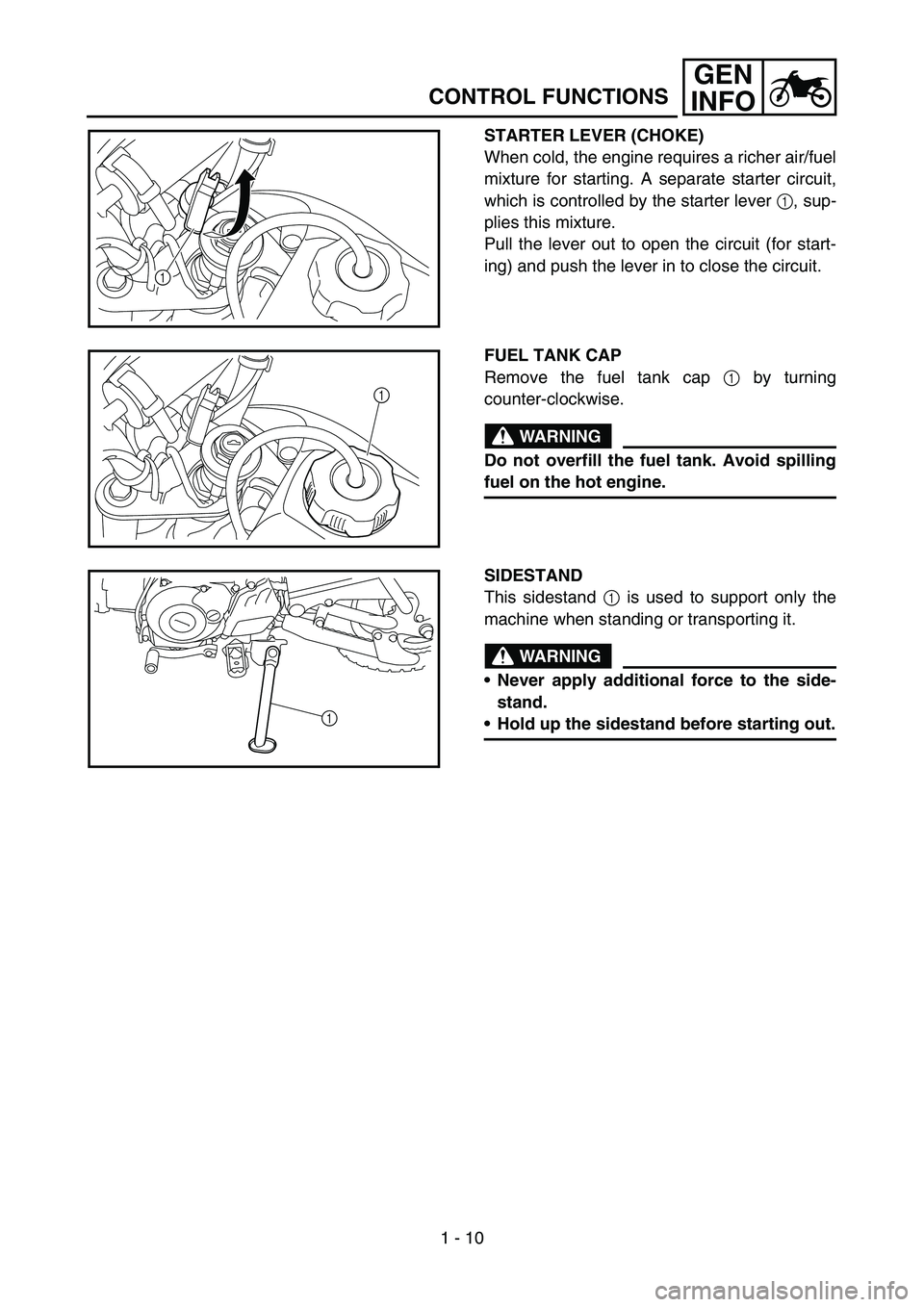
STARTER LEVER (CHOKE)
When cold, the engine requires a richer air/fuel
mixture for starting. A separate starter circuit,
which is controlled by the starter lever 1, sup-
plies this mixture.
Pull the lever out to open the circuit (for start-
ing) and push the lever in to close the circuit.
1
FUEL TANK CAP
Remove the fuel tank cap 1 by turning
counter-clockwise.
WARNING
Do not overfill the fuel tank. Avoid spilling
fuel on the hot engine.
1
SIDESTAND
This sidestand 1 is used to support only the
machine when standing or transporting it.
WARNING
Never apply additional force to the side-
stand.
Hold up the sidestand before starting out.1
Page 61 of 390

SPEC
2 - 6
Stem runout limit ---- 0.01 mm
(0.0004 in)
Valve seat width IN 0.9 ~ 1.1 mm (0.0354 ~ 0.0433 in)1.6 mm
(0.0630 in)
EX 0.9 ~ 1.1 mm (0.0354 ~ 0.0433 in) 1.6 mm
(0.0630 in)
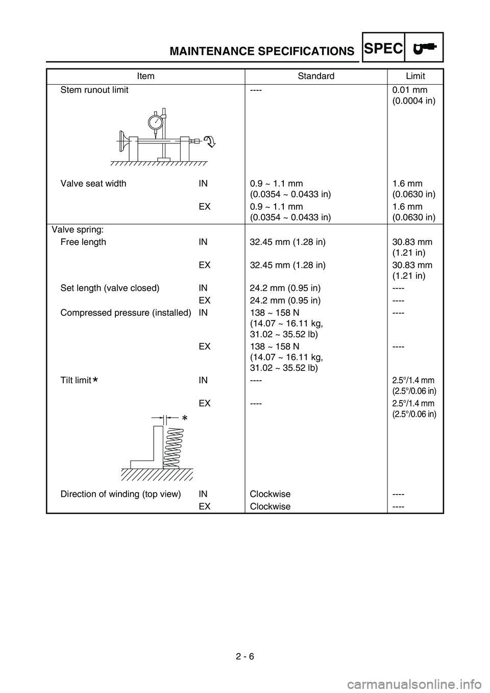
Valve spring: Free length IN 32.45 mm (1.28 in) 30.83 mm (1.21 in)
EX 32.45 mm (1.28 in) 30.83 mm (1.21 in)
Set length (valve closed) IN 24.2 mm (0.95 in) ---- EX 24.2 mm (0.95 in) ----
Compressed pressure (installed) IN 138 ~ 158 N (14.07 ~ 16.11 kg,
31.02 ~ 35.52 lb)----
EX 138 ~ 158 N (14.07 ~ 16.11 kg,
31.02 ~ 35.52 lb) ----
Tilt limit IN ----
2.5 °/1.4 mm
(2.5 °/0.06 in)
EX ----2.5 °/1.4 mm
(2.5 °/0.06 in)
Direction of winding (top view) IN Clockwise ----
EX Clockwise ----
Item Standard Limit
*
MAINTENANCE SPECIFICATIONS
Page 144 of 390

3 - 11
INSPADJ
VALVE CLEARANCE ADJUSTMENT
3. Check:
Valve clearance
Out of specification → Adjust.
Valve clearance (cold):
Intake valve: 0.05 ~ 0.09 mm
(0.0020 ~ 0.0035 in)
Exhaust valve: 0.08 ~ 0.12 mm
(0.0031 ~ 0.0047 in)
Checking steps:
Turn the crankshaft counterclockwise with
a wrench.
When the piston is at T.D.C. on the com-
pression stroke, align the “I” mark a on
the camshaft sprocket with the stationary
pointer b on the cylinder head.
Align the “I” mark c on the rotor with the
stationary pointer d on the crankcase
cover.
Measure the valve clearance using a
thickness gauge 1.
Out of specification → Adjust clearance.
Thickness gauge:
YM-34483/90890-03079
a
b
d
c
1
Page 156 of 390

3 - 17
INSPADJ
6. Lubricate:
Drive chain
Drive chain lubricant:
SAE 10W-30 motor oil or
suitable chain lubricants
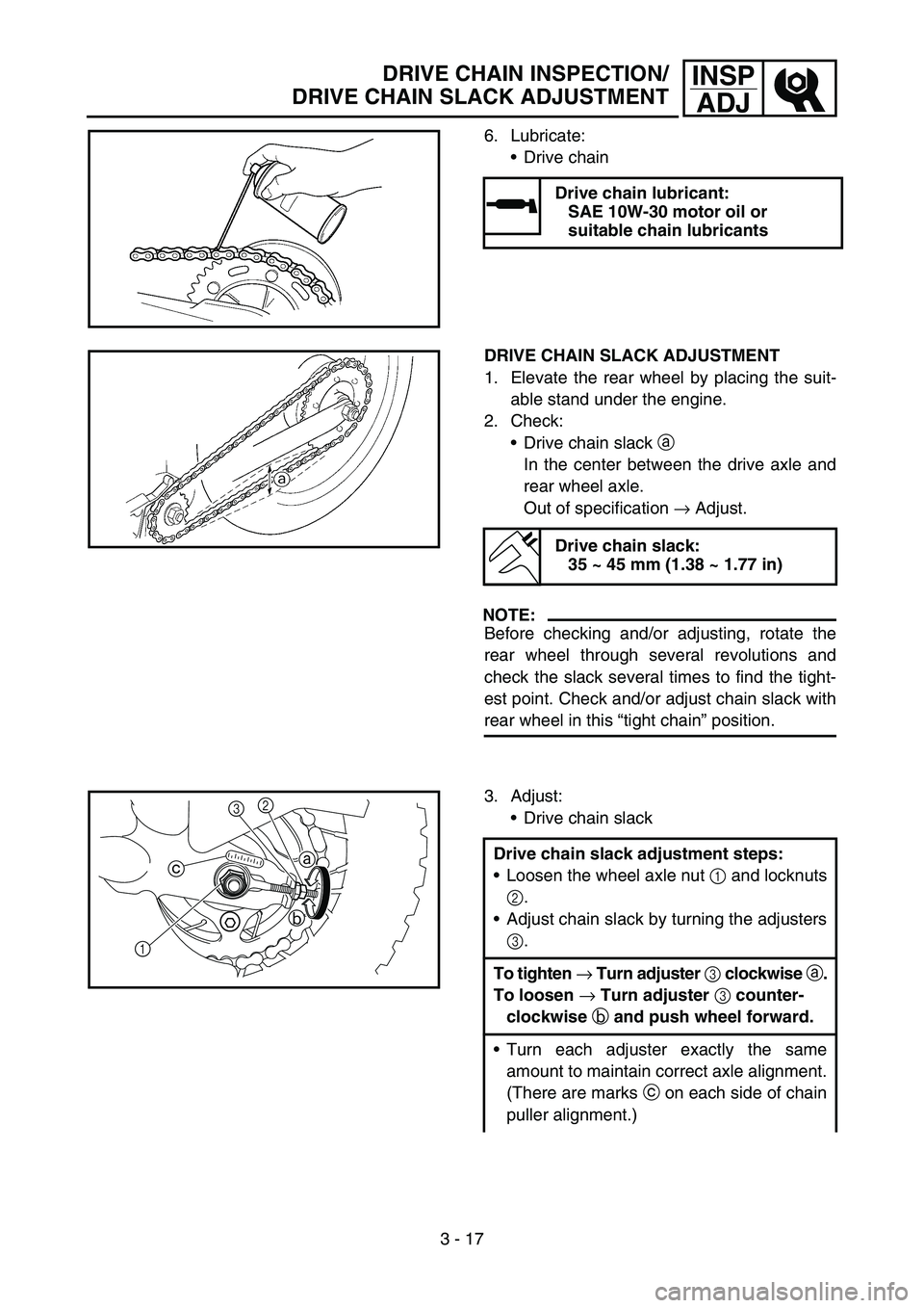
DRIVE CHAIN SLACK ADJUSTMENT
1. Elevate the rear wheel by placing the suit-
able stand under the engine.
2. Check: Drive chain slack a
In the center between the drive axle and
rear wheel axle.
Out of specification → Adjust.
NOTE:
Before checking and/or adjusting, rotate the
rear wheel through several revolutions and
check the slack several times to find the tight-
est point. Check and/or adjust chain slack with
rear wheel in this “tight chain ” position.
Drive chain slack:
35 ~ 45 mm (1.38 ~ 1.77 in)
3. Adjust:
Drive chain slack
Drive chain slack adjustment steps:
Loosen the wheel axle nut 1 and locknuts
2 .
Adjust chain slack by turning the adjusters
3 .
To tighten → Turn adjuster 3 clockwise a.
To loosen → Turn adjuster 3 counter-
clockwise b and push wheel forward.
Turn each adjuster exactly the same
amount to maintain correct axle alignment.
(There are marks c on each side of chain
puller alignment.)
1 b
c
a
23
DRIVE CHAIN INSPECTION/
DRIVE CHAIN SLACK ADJUSTMENT
Page 210 of 390

4 - 12
ENGCYLINDER HEAD
REMOVAL POINTS
Cylinder head
1. Align:“I” mark
(with stationary pointer)
Checking steps:
Turn the crankshaft counterclockwise with
a wrench.
Align the “I” mark a on the rotor with the
stationary pointer b on the crankcase
cover. When the “I” mark is aligned with
the stationary pointer, the piston is at the
Top Dead Center (T.D.C.).
NOTE:
In order to be sure that the piston is at Top
Dead Center, the “I” mark c on the cam-
shaft sprocket must align with the station-
ary pointer d on the cylinder head as
shown in the illustration.
If there is no valve clearance, rotate the
crankshaft counterclockwise one turn.
b
a
c
d
2. Loosen:
Camshaft sprocket bolt 1
3. Remove:
Timing chain tensioner
Camshaft sprocket 2
NOTE:
Fasten a safety wire to the timing chain 3 to
prevent it from falling into the crankcase.
Remove the bolt 1 while holding the rotor
nut with a wrench.
12
3
Page 212 of 390

4 - 13
ENGCYLINDER HEAD
4. Remove:Cylinder head
NOTE:
Loosen the bolts and nuts in their proper
loosening sequence.
Start by loosening each bolt and nut 1/2 turn
until all are loose.1
2
5
64
3
ASSEMBLY AND INSTALLATION
1. Install:
Cylinder head
2. Tighten: Nuts
Bolts
NOTE:
Apply the engine oil on the contact surfaces
of the nuts and copper washers.
Apply the engine oil on the thread and con-
tact surface of the bolts.
Follow the numerical order shown in the illus-
tration. Tighten the bolts and nuts in two
stages.
6
5
2
13
4
T R..22 Nm (2.2 m · kg, 16 ft · lb)
T R..10 Nm (1.0 m · kg, 7.2 ft · lb)
3. Install:
Camshaft sprocket 1
Installation steps:
Turn the crankshaft counterclockwise until
the “I” mark a on the rotor is aligned with
the stationary pointer b on the crankcase
cover.
Align the “I” mark c on the camshaft
sprocket with the stationary pointer d on
the cylinder head.
Fit the timing chain 2 onto camshaft
sprocket and install the camshaft sprocket
on the camshaft.
NOTE:
When installing the camshaft sprocket, keep
the timing chain as tense as possible on the
exhaust side.
b
a
1
2
c
d
Page 258 of 390

4 - 36
ENG
Clutch free play adjustment
1. Adjust:Clutch free play
Adjustment steps:
Loosen the locknut 1.
Turn the clutch adjuster 2 counterclock-
wise until it becomes slightly difficult to
turn.
Turn the clutch adjuster 2 clockwise 1/8
turn.
Hold the clutch adjuster 2 and tighten the
locknut 1.
T R..
Locknut:
6 Nm (0.6 m kg, 4.3 ft lb)
1
2
CLUTCH
Page 276 of 390

4 - 45
ENG
INSPECTION
Starter clutch
1. Inspect:Starter idle gear teeth a
Starter drive gear teeth b
Starter wheel gear teeth c
Burrs/chips/roughness/wear → Replace.
2. Check:
Starter clutch operation.
Checking steps:
Install the starter wheel gear onto the
starter clutch and hold the starter clutch.
When turning the starter wheel gear clock-
wise È, the starter clutch and the starter
wheel gear should be engage, otherwise
the starter clutch is faulty and must be
replaced.
When turning the starter wheel gear coun-
terclockwise É, it should turn freely, other-
wise the starter clutch is faulty and must
be replaced.
É
È
ASSEMBLY AND INSTALLATION
Starter clutch
1. Install:Starter clutch 1
1T R..14 Nm (1.4 m · kg, 10 ft · lb)
2. Unloosen the starter clutch assembly by
using the center punch.
AC MAGNETO AND STARTER CLUTCH