stop start YAMAHA TTR50 2006 Owners Manual
[x] Cancel search | Manufacturer: YAMAHA, Model Year: 2006, Model line: TTR50, Model: YAMAHA TTR50 2006Pages: 390, PDF Size: 9.69 MB
Page 26 of 390
1 - 1
GEN
INFO
DESCRIPTION
EC100000
GENERAL INFORMATION
EC110000
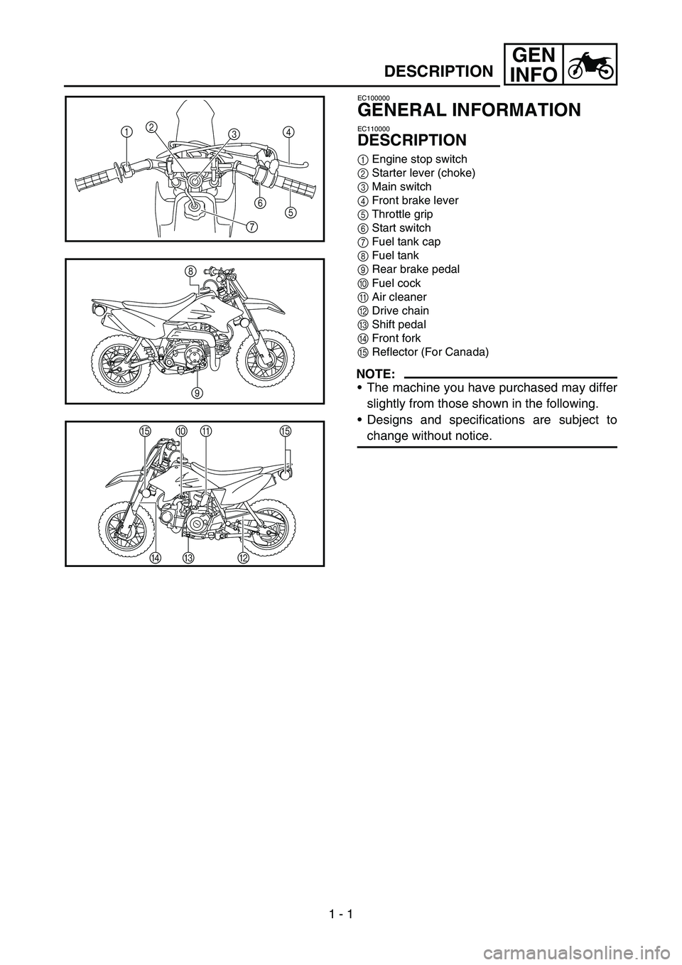
DESCRIPTION
1 Engine stop switch
2 Starter lever (choke)
3 Main switch
4 Front brake lever
5 Throttle grip
6 Start switch
7 Fuel tank cap
8 Fuel tank
9 Rear brake pedal
0 Fuel cock
A Air cleaner
B Drive chain
C Shift pedal
D Front fork
E Reflector (For Canada)
NOTE:
The machine you have purchased may differ
slightly from those shown in the following.
Designs and specifications are subject to
change without notice.
1
4
7
5
2 6
3
\b
8
EE
0\f
DC B
1
Page 27 of 390
GEN
INFO
ALLGEMEINES
FAHRZEUGBESCHREIBUNG
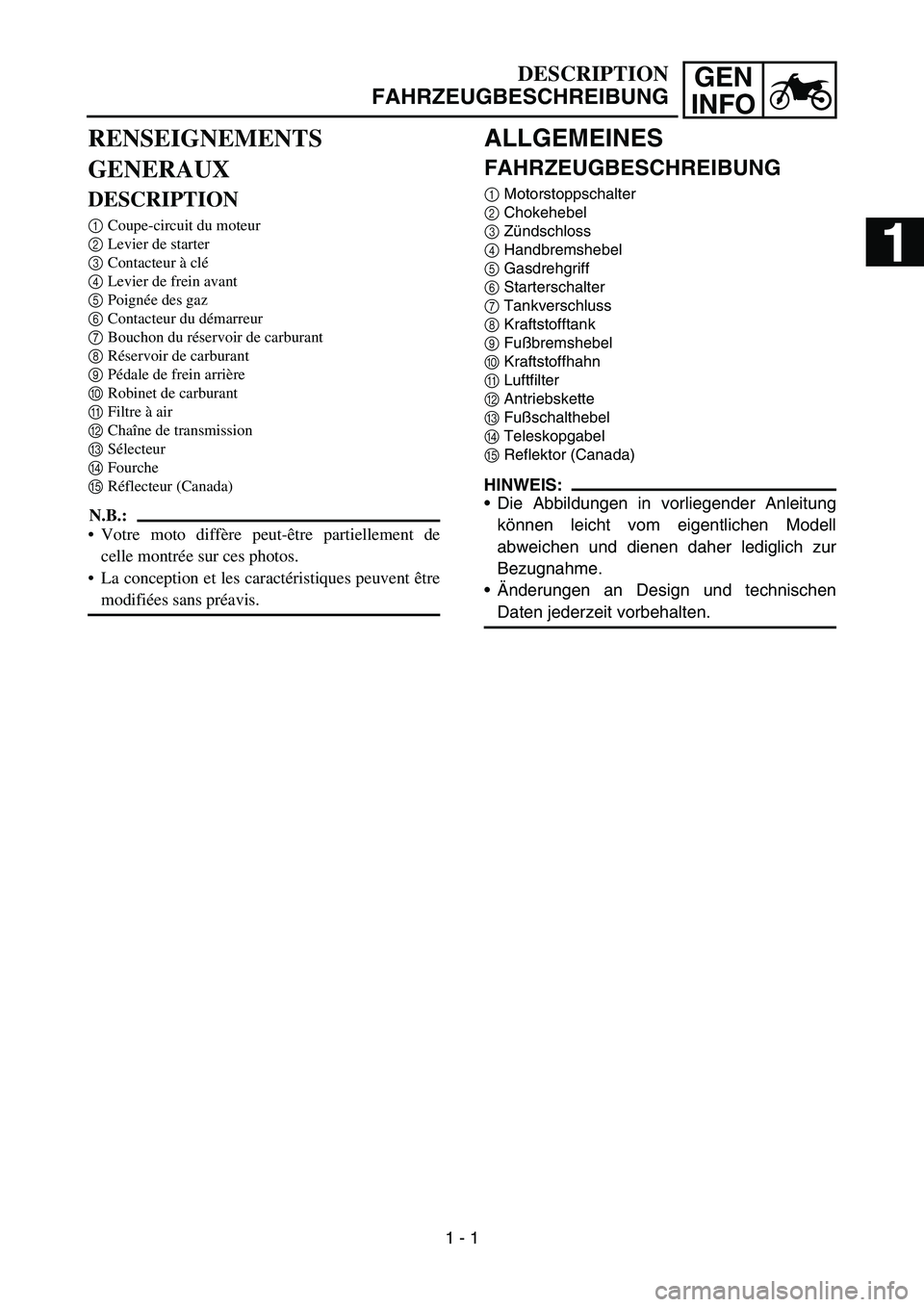
1 Motorstoppschalter
2 Chokehebel
3 Zündschloss
4 Handbremshebel
5 Gasdrehgriff
6 Starterschalter
7 Tankverschluss
8 Kraftstofftank
9 Fußbremshebel
0 Kraftstoffhahn
A Luftfilter
B Antriebskette
C Fußschalthebel
D Teleskopgabel
E Reflektor (Canada)
HINWEIS:
Die Abbildungen in vorliegender Anleitung
können leicht vom eigentlichen Modell
abweichen und dienen daher lediglich zur
Bezugnahme.
Änderungen an Design und technischen
Daten jederzeit vorbehalten.
DESCRIPTION
FAHRZEUGBESCHREIBUNG
RENSEIGNEMENTS
GENERAUX
DESCRIPTION
1 Coupe-circuit du moteur
2 Levier de starter
3 Contacteur à clé
4 Levier de frein avant
5 Poignée des gaz
6 Contacteur du démarreur
7 Bouchon du réservoir de carburant
8 Réservoir de carburant
9 Pédale de frein arrière
0 Robinet de carburant
A Filtre à air
B Chaîne de transmission
C Sélecteur
D Fourche
E Réflecteur (Canada)
N.B.:
Votre moto diffère peut-être partiellement de
celle montrée sur ces photos.
La conception et les caractéristiques peuvent être
modifiées sans préavis.
1 - 1
1
2
3
4
5
6
Page 42 of 390
1 - 8
GEN
INFO
CONTROL FUNCTIONS
EC150000
CONTROL FUNCTIONS
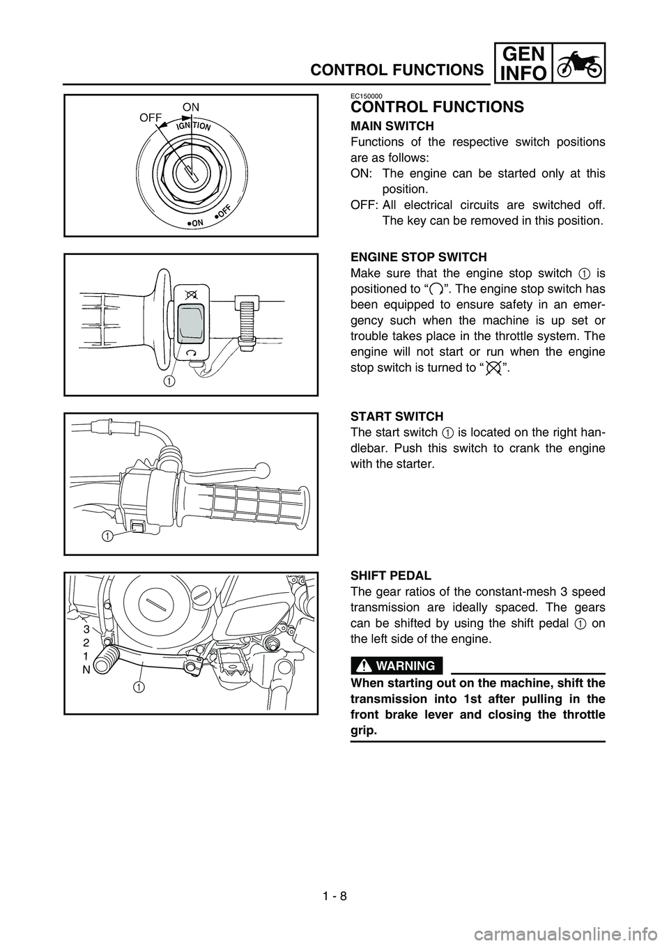
MAIN SWITCH
Functions of the respective switch positions
are as follows:
ON: The engine can be started only at this
position.
OFF: All electrical circuits are switched off. The key can be removed in this position.
ENGINE STOP SWITCH
Make sure that the engine stop switch 1 is
positioned to “”. The engine stop switch has
been equipped to ensure safety in an emer-
gency such when the machine is up set or
trouble takes place in the throttle system. The
engine will not start or run when the engine
stop switch is turned to “”.
START SWITCH
The start switch 1 is located on the right han-
dlebar. Push this switch to crank the engine
with the starter.
1
SHIFT PEDAL
The gear ratios of the constant-mesh 3 speed
transmission are ideally spaced. The gears
can be shifted by using the shift pedal 1 on
the left side of the engine.
WARNING
When starting out on the machine, shift the
transmission into 1st after pulling in the
front brake lever and closing the throttle
grip.
3
2
1
N
1
Page 43 of 390
GEN
INFO
BEDIENUNGSELEMENTE UND
DEREN FUNKTION
Z Ü NDSCHLOSS
Die einzelnen Z ündschl üssel-Stellungen sind
nachfolgend beschrieben:
ON: Nur in dieser Stellung kann der Motor gestartet werden.
OFF: Alle elektrischen Stromkreise sind aus- geschaltet. Der Schl üssel kann in dieser
Stellung abgezogen werden.
MOTORSTOPPSCHALTER
Sicherstellen, dass der Motorstoppschalter 1
auf “” steht. Der Motorstoppschalter dient
dazu, den Motor in einer Notsituation (wie
einem Sturz oder einem klemmenden Gas-
drehgriff) rasch ausschalten zu k önnen. Der
Motor kann in der Motorstoppschalter-Stel-
lung “” nicht angelassen werden.
STARTERSCHALTER
Der Starterschalter 1 befindet sich rechts am
Lenker. Diesen Schalter dr ücken, um den
Motor anzulassen.
FUSSSCHALTHEBEL
Das 3-Gang-Getriebe dieses Motorrads ist
ideal abgestuft. Die G änge werden über den
Fu ßschalthebel 1 links am Motor geschaltet.
WARNUNG
Zum Anfahren das Getriebe bei gezogenem
Handbremshebel und geschlossenem Gas-
drehgriff in den ersten Gang schalten.
FONCTIONS DES COMMANDES
BEDIENUNGSELEMENTE UND DEREN FUNKTION
FONCTIONS DES COMMANDES
CONTACTEUR A CLE
Les fonctions correspondant aux diff érentes posi-
tions du contacteur sont les suivantes:
ON: seule position permettant le d émarrage du
moteur.
OFF: tous les circuits électriques sont coup és. La
cl é peut être retir ée dans cette position.
COUPE-CIRCUIT DU MOTEUR
Bien veiller à ce que le coupe-circuit du moteur 1
soit plac é sur “” . Cette moto est équip ée d ’un
coupe-circuit du moteur afin de couper le moteur en
cas d ’urgence, par exemple lorsqu ’un probl ème se
produit dans le syst ème d ’acc élé ration. Le moteur
ne d émarre pas ou s ’arr ête d ès que le coupe-circuit
est plac é en position “”.
CONTACTEUR DU DEMARREUR
Le contacteur du d émarreur 1 est situ é sur la partie
droite du guidon. Appuyer sur ce contacteur pour
lancer le moteur à l ’aide du d émarreur.
SELECTEUR
Les 3 rapports de la bo îte de vitesses à prise cons-
tante sont id éalement échelonn és. Le changement
de vitesse est command é par le s électeur 1 situ é
sur le c ôté gauche du moteur.
AVERTISSEMENT
Pour d émarrer, passer en premi ère apr ès avoir
serr é le levier de frein avant et ferm é la poign ée
des gaz.
1 - 8
Page 50 of 390
GEN
INFO
1 - 12
STARTING AND OPERATION
STARTING AND OPERATION
CAUTION:
Prior to operating the machine, perform
steps listed in pre-operation check list.
WARNING
Never start your engine or let it run for any
length of time in a closed area. The exhaust
fumes are poisonous and can cause loss of
consciousness and death within a short
time. Always operate your machine in an
area with adequate ventilation.
STARTING A COLD ENGINE
WARNING
Before starting the engine, be sure to shift
the transmission into neutral.
NOTE:
This model is equipped with an ignition cir-
cuit cut-off system. In case of electric start-
ing, the engine can be started only when the
transmission is in neutral.
If the engine fails to start by pushing the start
switch, release the switch, wait a few sec-
onds, and then try again. Each starting
attempt should be as short as possible to
preserve the battery. Do not crank the
engine more than 10 seconds on any one
attempt.
1. Turn the fuel cock to “ON ”.
2. Turn the main switch to “ON ”.
3. Shift the transmission into neutral.
4. Operate the starter (choke) and completely close the throttle grip.
5. Slide the “engine stop ” switch to the “”.
6. Start the engine by pushing the start switch.
7. After the engine starts, warm up for one or
two minutes. Make sure the stater (choke) is
returned to the original position before riding. STARTING A WARM ENGINE
To start a warm engine, refer to the
“START-
ING A COLD ENGINE ” section. The starter
(choke) should not be used. The throttle
should be opened slightly.
CAUTION:
See “Engine break-in Section ” prior to
operating engine for the first time.
WARMING UP
To get maximum engine life, always “warm-up ”
the engine before starting off. Never accelerate
hard with a cold engine! To see whether or not
the engine is warm, see if it responds to throttle
normally with the stater (choke) turned off.
WARNING
Before starting off, be sure to turn up or
remove the side stand.
Failure to retract the side stand completely
can result in a serious accident when you
try to turn a corner.
ENGINE BREAK-IN
Break-in is important to better fit the moving
and sliding parts as well as the installed parts.
It is also important to accustom the rider to the
machine better.
Avoid full-throttle run on a new machine for the
first 5 hours.
After the trial run, check for loose parts, oil
leakage and other problems.
Make full inspection and adjustment especially of
slack cables and drive chain and loose spokes.
CAUTION:
After the break-in period, check every fit-
ting and fastener for looseness.
If any loose is found, retighten it securely.
Page 52 of 390
GEN
INFO
ANLASSEN UND
INBETRIEBNAHME
ACHTUNG:
Vor dem Start muss die “Routinekontrolle
vor Fahrtbeginn ” ausgef ührt werden.
WARNUNG
Den Motor niemals in einem geschlosse-
nen Raum anlassen oder betreiben. Motor-
abgase sind äu ßerst giftig und f ühren in
kurzer Zeit zu Bewusstlosigkeit und Tod.
Daher den Motor nur an einem gut bel üfte-
ten Ort betreiben.
KALTEN MOTOR ANLASSEN
WARNUNG
Vor dem Anlassen sicherstellen, dass das
Getriebe in der Leerlaufstellung ist.
HINWEIS:
Das Motorrad ist mit einem Z ündunterbre-
chungs- und Anlasssperrschalter-System
ausger üstet. Der Motor kann nur dann mit
dem E-Starter angelassen werden, wenn
das Getriebe in der Leerlaufstellung ist.
Falls der Motor bei Verwendung des Elektro-
starters nicht sofort anspringt, den Starter-
schalter freigeben und einige Sekunden bis
zum n ächsten Startversuch warten. Um die
Batterie zu schonen, darf der Starterschalter
jeweils nur kurzzeitig bet ätigt werden. Den
Motor niemals l änger als 10 Sekunden dre-
hen.
1. Den Kraftstoffhahn auf “ON ” stellen.
2. Den Z ündschl üssel auf “ON ” stellen.
3. Das Getriebe in die Leerlaufstellung schal- ten.
4. Den Choke bet ätigen und den Gasdrehgriff
ganz schlie ßen.
5. Den Motorstoppschalter auf “” stellen.
6. Den Starterschalter dr ücken, um den Motor
anzulassen.
7. Nach dem Anlassen den Motor einige Minu- ten lang warm laufen lassen. Vor dem
Anfahren sicherstellen, dass der Chokehe-
bel in die Ausgangsstellung zur ückgebracht
wird. WARMEN MOTOR ANLASSEN
Den warmen Motor wie im Abschnitt
“KALTEN
MOTOR ANLASSEN ” beschrieben anlassen.
Allerdings sollte der Choke nicht bet ätigt wer-
den. Den Gasdrehgriff leicht öffnen.
ACHTUNG:
Vor der ersten Inbetriebnahme unbedingt
den Abschnitt “Einfahrvorschriften ” beach-
ten.
MOTOR WARM FAHREN
Den Motor stets warm fahren, um ihm eine
lange Lebensdauer zu gew ähren. Bei kaltem
Motor niemals stark beschleunigen! Der Motor
ist ausreichend warm gefahren, wenn er bei
abgeschaltetem Choke willig auf Gasgeben
anspricht.
WARNUNG
Vor dem Losfahren sicherstellen, dass der
Seitenst änder hochgeklappt bzw. abge-
nommen ist.
Ein ausgeklappter Seitenst änder kann in
Kurven schwere St ürze verursachen.
EINFAHRVORSCHRIFTEN
Die Einfahrzeit ist wichtig, weil sie den vielen
Bauteilen des Motors erlaubt, sich einzupas-
sen. Au ßerdem kann der Fahrer sich w ährend
dessen mit seiner Maschine vertraut machen.
W ährend der ersten f ünf Betriebsstunden
unbedingt Vollgas vermeiden.
Nach der Probefahrt die Maschine auf lockere
Schraubverbindungen, Öllecks und andere
Probleme untersuchen.
Die Maschine gr ündlich kontrollieren und einstel-
len, insbesondere Seilz üge, Antriebskette und
Radspeichen.
ACHTUNG:
Am Ende der Einfahrzeit sicherstellen,
dass s ämtliche Schraubverbindungen fest
sind.
Bei Lockerheit nachziehen.
ANLASSEN UND INBETRIEBNAHME
1 - 12
Page 53 of 390
GEN
INFO
1 - 13
CLEANING AND STORAGE
EC1B0000
CLEANING AND STORAGE
EC1B1000
CLEANING
Frequent cleaning of your machine will
enhance its appearance, maintain good overall
performance, and extend the life of many com-
ponents.
1. Before washing the machine, block off the
end of the exhaust pipe to prevent water
from entering.
2. If the engine is excessively greasy, apply some degreaser to it with a paint brush. Do
not apply degreaser to the chain, sprock-
ets, or wheel axles.
3. Rinse the dirt and degreaser off with a gar- den hose; use only enough pressure to do
the job.
CAUTION:
Excessive hose pressure may cause water
seepage and contamination of wheel bear-
ings, front forks, brakes and transmission
seals. Many expensive repair bills have
resulted from improper high pressure
detergent applications such as those avail-
able in coin-operated car washers.
4. After the majority of the dirt has been hosed off, wash all surfaces with warm
water and a mild detergent. Use an old
toothbrush to clean hard-to-reach places.
5. Rinse the machine off immediately with clean water, and dry all surfaces with a soft
towel or cloth.
6. Immediately after washing, remove excess water from the chain with a paper towel
and lubricate the chain to prevent rust.
7. Clean the seat with a vinyl upholstery cleaner to keep the cover pliable and
glossy.
8. Automotive wax may be applied to all
painted or chromed surfaces. Avoid combi-
nation cleaner-waxes, as they may contain
abrasives.
9. After completing the above, start the engine and allow it to idle for several min-
utes.
EC182001
STORAGE
If your machine is to be stored for 60 days or
more, some preventive measures must be
taken to avoid deterioration. After cleaning the
machine thoroughly, prepare it for storage as
follows:
1. Drain the fuel tank, fuel lines, and the car-
buretor float bowl.
2. Remove the spark plug, pour a tablespoon of SAE 10W-30 motor oil in the spark plug
hole, and reinstall the plug. Set the engine
stop switch to “”, turn the engine over
several times with starter. (This will coat
the cylinder walls with oil.)
3. Remove the drive chain, clean it thoroughly with solvent, and lubricate it. Reinstall the
chain or store it in a plastic bag tied to the
frame.
4. Lubricate all control cables.
5. Block the frame up to raise the wheels off the ground.
6. Tie a plastic bag over the exhaust pipe out-
let to prevent moisture from entering.
7. If the machine is to be stored in a humid or salt-air environment, coat all exposed
metal surfaces with a film of light oil. Do not
apply oil to rubber parts or the seat cover.
NOTE:
Make any necessary repairs before the
machine is stored.
Page 55 of 390
GEN
INFO
PFLEGE UND LAGERUNG
FAHRZEUGW ÄSCHE
Regelm äßige W äsche optimiert das Ausse-
hen, die Leistung und die Lebensdauer des
Motorrads und seiner Bestandteile.
1. Vor der Fahrzeugw äsche den Schalld ämp-
fer zudecken, damit kein Wasser eindrin-
gen kann.
2. Falls der Motor stark ver ölt ist, einen Kalt-
reiniger mit dem Pinsel auftragen. Kaltreini-
ger von Kette, Kettenr ädern und
Radachsen fern halten.
3. Schmutz und Kaltreiniger mit einem schwa-
chen Wasserstrahl absp ülen.
ACHTUNG:
Ein Hochdruck-Wasserstrahl k önnte
Feuchtigkeit in Radlager, Teleskopgabel,
Bremsen und Getriebe eindr ücken. Dampf-
strahler an Tankstellen und M ünzwaschan-
lagen sind die Ursache vieler teuren
Reparaturen.
4. Nach dem Absp ülen s ämtliche Oberfl ä-
chen mit warmem Wasser und einem mil-
den Reinigungsmittel waschen. Schwer
zug ängliche Stellen mit einer B ürste reini-
gen.
5. Das Motorrad umgehend mit sauberem Wasser absp ülen und mit einem weichen
Tuch gr ündlich abtrocknen.
6. Die Antriebskette anschlie ßend mit einem
Papierhandtuch trockenreiben und sofort
schmieren, damit sie nicht rostet.
7. Die Sitzbank mit einem Kunststoffpflege- mittel behandeln.
8. Alle lackierten und verchromten Oberfl ä-
chen mit Pflegewachs behandeln. Keine
Pflegemittel mit Scheurmitteln verwenden,
um Kratzer zu vermeiden.
9. Anschlie ßend den Motor anlassen und
einige Minuten lang betreiben. LAGERUNG
Soll das Motorrad l
änger als 60 Tage gelagert
werden, sind gewisse Schutzma ßnahmen not-
wendig. Das Motorrad nach der W äsche, wie
nachfolgend beschrieben, auf die Lagerung
vorbereiten:
1. Das Benzin aus dem Kraftstofftank ablas- sen und den Vergaser entleeren.
2. Die Z ündkerze herausdrehen, einen Ess-
l ö ffel SAE 10W-30-Motor öl in die Z ündker-
zenbohrung gie ßen und die Z ündkerze
wieder eindrehen. Den Motorstoppschalter
auf “” stellen und den Motor mehrmals
mit dem Starter drehen. (Dadurch werden
die Zylinderwandungen mit Öl bedeckt.)
3. Die Antriebskette abnehmen, gr ündlich rei-
nigen und anschlie ßend schmieren. Die
Kette montieren oder in einem am Rahmen
angebundenen Plastikbeutel aufbewahren.
4. S ämtliche Seilz üge ölen.
5. Das Motorrad so abst ützen, dass die
R äder sich frei drehen lassen.
6. Einen Plastikbeutel über die Schalld ämp-
fer öffnung binden, damit keine Feuchtigkeit
eindringt.
7. Ist der Lagerort feucht oder salzhaltig, sä mtliche Metallfl ächen mit Spr üh öl behan-
deln. Öl von Gummiteilen und der Sitzbank
fern halten.
HINWEIS: Anfallende Reparaturen oder Inspektion vor
der Stilllegung ausf ühren.
PFLEGE UND LAGERUNG
1 - 13
Page 65 of 390
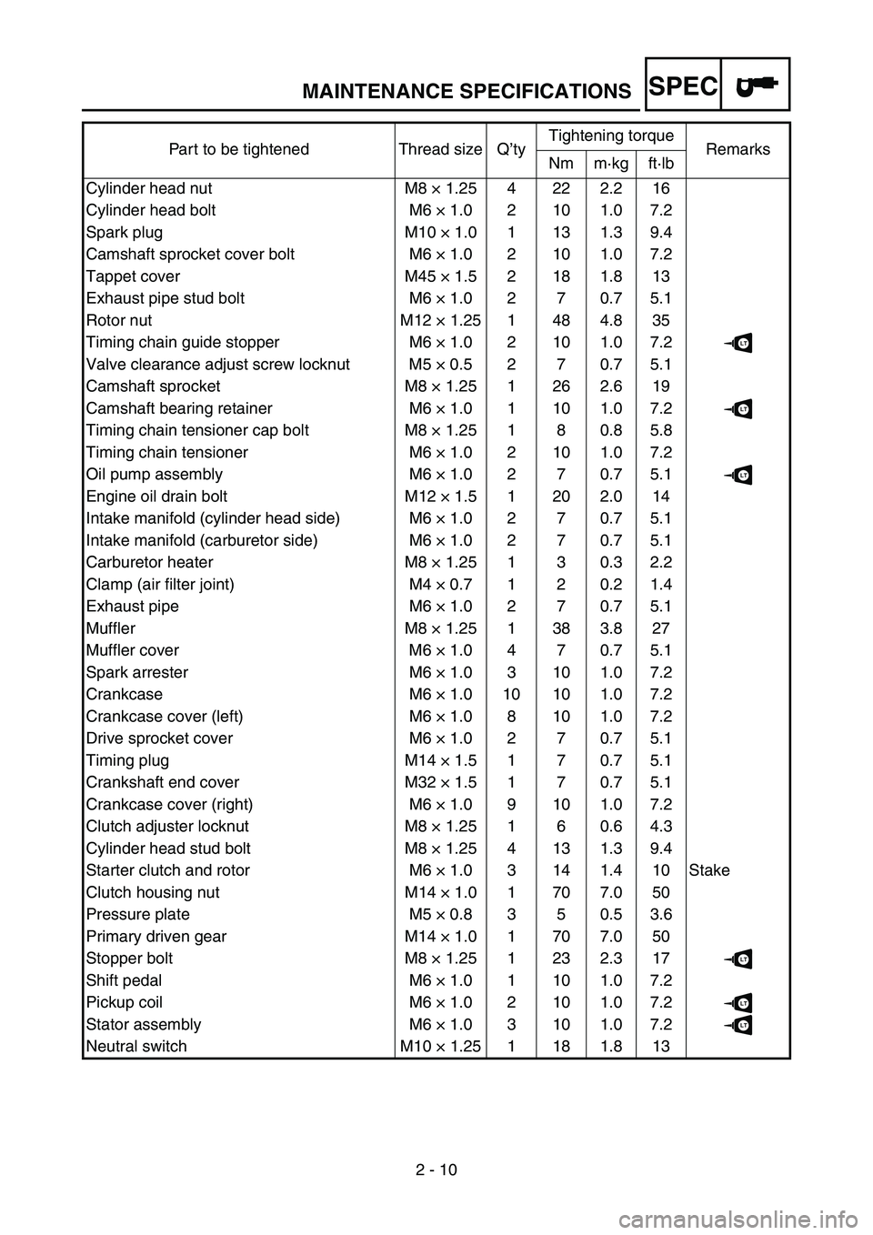
SPEC
2 - 10
Part to be tightened Thread size Q
’ty Tightening torque
Remarks
Nm m ·kg ft ·lb
Cylinder head nut M8 × 1.25 4 22 2.2 16
Cylinder head bolt M6 × 1.0 2 10 1.0 7.2
Spark plug M10 × 1.0 1 13 1.3 9.4
Camshaft sprocket cover bolt M6 × 1.0 2 10 1.0 7.2
Tappet cover M45 × 1.5 2 18 1.8 13
Exhaust pipe stud bolt M6 × 1.0 2 7 0.7 5.1
Rotor nut M12 × 1.25 1 48 4.8 35
Timing chain guide stopper M6 × 1.0 2 10 1.0 7.2
LT
Valve clearance adjust screw locknut M5 × 0.5 2 7 0.7 5.1
Camshaft sprocket M8 × 1.25 1 26 2.6 19
Camshaft bearing retainer M6 × 1.0 1 10 1.0 7.2
LT
Timing chain tensioner cap bolt M8 × 1.25 1 8 0.8 5.8
Timing chain tensioner M6 × 1.0 2 10 1.0 7.2
Oil pump assembly M6 × 1.0 2 7 0.7 5.1
LT
Engine oil drain bolt M12 × 1.5 1 20 2.0 14
Intake manifold (cylinder head side) M6 × 1.0 2 7 0.7 5.1
Intake manifold (carburetor side) M6 × 1.0 2 7 0.7 5.1
Carburetor heater M8 × 1.25 1 3 0.3 2.2
Clamp (air filter joint) M4 × 0.7 1 2 0.2 1.4
Exhaust pipe M6 × 1.0 2 7 0.7 5.1
Muffler M8 × 1.25 1 38 3.8 27
Muffler cover M6 × 1.0 4 7 0.7 5.1
Spark arrester M6 × 1.0 3 10 1.0 7.2
Crankcase M6 × 1.0 10 10 1.0 7.2
Crankcase cover (left) M6 × 1.0 8 10 1.0 7.2
Drive sprocket cover M6 × 1.0 2 7 0.7 5.1
Timing plug M14 × 1.5 1 7 0.7 5.1
Crankshaft end cover M32 × 1.5 1 7 0.7 5.1
Crankcase cover (right) M6 × 1.0 9 10 1.0 7.2
Clutch adjuster locknut M8 × 1.25 1 6 0.6 4.3
Cylinder head stud bolt M8 × 1.25 4 13 1.3 9.4
Starter clutch and rotor M6 × 1.0 3 14 1.4 10 Stake
Clutch housing nut M14 × 1.0 1 70 7.0 50
Pressure plate M5 × 0.8 3 5 0.5 3.6
Primary driven gear M14 × 1.0 1 70 7.0 50
Stopper bolt M8 × 1.25 1 23 2.3 17
LT
Shift pedal M6 × 1.0 1 10 1.0 7.2
Pickup coil M6 × 1.0 2 10 1.0 7.2
LT
Stator assembly M6 × 1.0 3 10 1.0 7.2LT
Neutral switch M10 × 1.25 1 18 1.8 13
MAINTENANCE SPECIFICATIONS
Page 104 of 390

2 - 17
SPECCABLE ROUTING DIAGRAM
CABLE ROUTING DIAGRAM
1 CDI unit lead
2 Lead guide
3 Carburetor heater
4 Carburetor heater lead flat terminal
5 Carburetor heater lead L-shaped terminal
6 Cable guide
7 Start switch lead
8 Main switch lead
9 Engine stop switch lead 0
Starter cable
A Throttle cable
B Plastic locking tie
C Thermo switch lead
D Spark plug lead
E Carburetor air vent hose
F Crankcase breather hose
G AC magneto leads
H Wire harness
2
É
BÍ
B Ñ
BÏ
F Î
LÕ
\b
8 \b
×
0
\f Ø
E
E Ò 6
\f
7
8
\b
0
\f
C
D
H
H
7
J
I
I
K 8
7
\b
C
0
\f
E H
G 345
Ê
Ì
Ð
ÙÓ
Ô
Ô
È
B
A C
C
B
A
B-B
A-A
C-C
1