width YAMAHA TTR50 2006 Owners Manual
[x] Cancel search | Manufacturer: YAMAHA, Model Year: 2006, Model line: TTR50, Model: YAMAHA TTR50 2006Pages: 390, PDF Size: 9.69 MB
Page 56 of 390

SPEC
2 - 1
EC200000
SPECIFICATIONS
EC211000
GENERAL SPECIFICATIONS
Model name: TT-R50EV (USA, CDN, AUS, NZ)TT-R50E (Europe, ZA)
Model code number: 1P61 (USA) 1P62 (CDN)
1P63 (Europe, AUS, NZ, ZA)
Dimensions: Overall length 1,305 mm (51.4 in)
Overall width 595 mm (23.4 in)
Overall height 775 mm (30.5 in)
Seat height 555 mm (21.9 in)
Wheelbase 925 mm (36.4 in)
Minimum ground clearance 135 mm (5.31 in)
Dry weight: Without oil and fuel 54.0 kg (119 lb)
Engine: Engine type Air cooled 4-stroke, SOHC
Cylinder arrangement Forward-inclined single cylinder
Displacement 49.5 cm
3 (3.02 cu.in)
Bore × stroke 36.0 × 48.6 mm (1.42 × 1.91 in)
Compression ratio 9.5 : 1
Compression pressure (STD) 1,300 kPa (13 kg/cm
2, 185 psi) at 600 r/min
Starting system Electric starter
Lubrication system: Wet sump
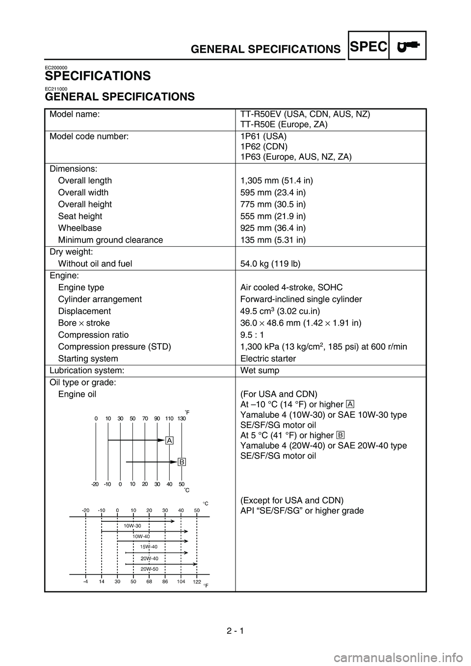
Oil type or grade: Engine oil
(For USA and CDN)
At –10 °C (14 °F) or higher È
Yamalube 4 (10W-30) or SAE 10W-30 type
SE/SF/SG motor oil
At 5 °C (41 °F) or higher É
Yamalube 4 (20W-40) or SAE 20W-40 type
SE/SF/SG motor oil
(Except for USA and CDN)
API “SE/SF/SG ” or higher grade
0 10 30 50 70 90 110 130
-20 -10 0 10
20
30 40 50
È
É
˚F
˚C
GENERAL SPECIFICATIONS
Page 60 of 390

SPEC
2 - 5
Rocker arm/rocker arm shaft:
Shaft outside diameter 9.981 ~ 9.991 mm (0.3930 ~ 0.3933 in)9.976 mm
(0.3928 in)
Rocker arm inside diameter 10.000 ~ 10.015 mm (0.3937 ~ 0.3943 in)10.025 mm
(0.3947 in)
Valve, valve seat, valve guide: Valve clearance (cold) IN 0.05 ~ 0.09 mm (0.0020 ~ 0.0035 in)----
EX 0.08 ~ 0.12 mm (0.0031 ~ 0.0047 in) ----
Valve dimensions:
“A ” head diameter IN 16.90 ~ 17.10 mm
(0.6653 ~ 0.6732 in)----
EX 14.40 ~ 14.60 mm (0.5669 ~ 0.5748 in) ----
“ B ” face width IN 1.05 ~ 1.55 mm
(0.0413 ~ 0.0610 in)----
EX 1.05 ~ 1.55 mm (0.0413 ~ 0.0610 in) ----
“ C ” seat width IN 0.9 ~ 1.1 mm
(0.0354 ~ 0.0433 in)1.6 mm
(0.0630 in)
EX 0.9 ~ 1.1 mm (0.0354 ~ 0.0433 in) 1.6 mm
(0.0630 in)
“ D ” margin thickness IN 0.5 ~ 0.9 mm
(0.0197 ~ 0.354 in)----
EX 0.5 ~ 0.9 mm (0.0197 ~ 0.0354 in) ----
Stem outside diameter IN 4.475 ~ 4.490 mm (0.1762 ~ 0.1768 in)4.445 mm
(0.1750 in)
EX 4.460 ~ 4.475 mm (0.1756 ~ 0.1762 in) 4.430 mm
(0.1744 in)
Guide inside diameter IN 4.500 ~ 4.512 mm (0.1772 ~ 0.1776 in)4.550 mm
(0.1791 in)
EX 4.500 ~ 4.512 mm (0.1772 ~ 0.1776 in) 4.550 mm
(0.1791 in)
Stem-to-guide clearance IN 0.010 ~ 0.037 mm (0.0004 ~ 0.0015 in)0.08 mm
(0.0031 in)
EX 0.025 ~ 0.052 mm (0.0010 ~ 0.0020 in) 0.10 mm
(0.0039 in)
Item Standard Limit
BC
DA
Head diameter Face width Seat width Margin thickness
MAINTENANCE SPECIFICATIONS
Page 61 of 390

SPEC
2 - 6
Stem runout limit ---- 0.01 mm
(0.0004 in)
Valve seat width IN 0.9 ~ 1.1 mm (0.0354 ~ 0.0433 in)1.6 mm
(0.0630 in)
EX 0.9 ~ 1.1 mm (0.0354 ~ 0.0433 in) 1.6 mm
(0.0630 in)
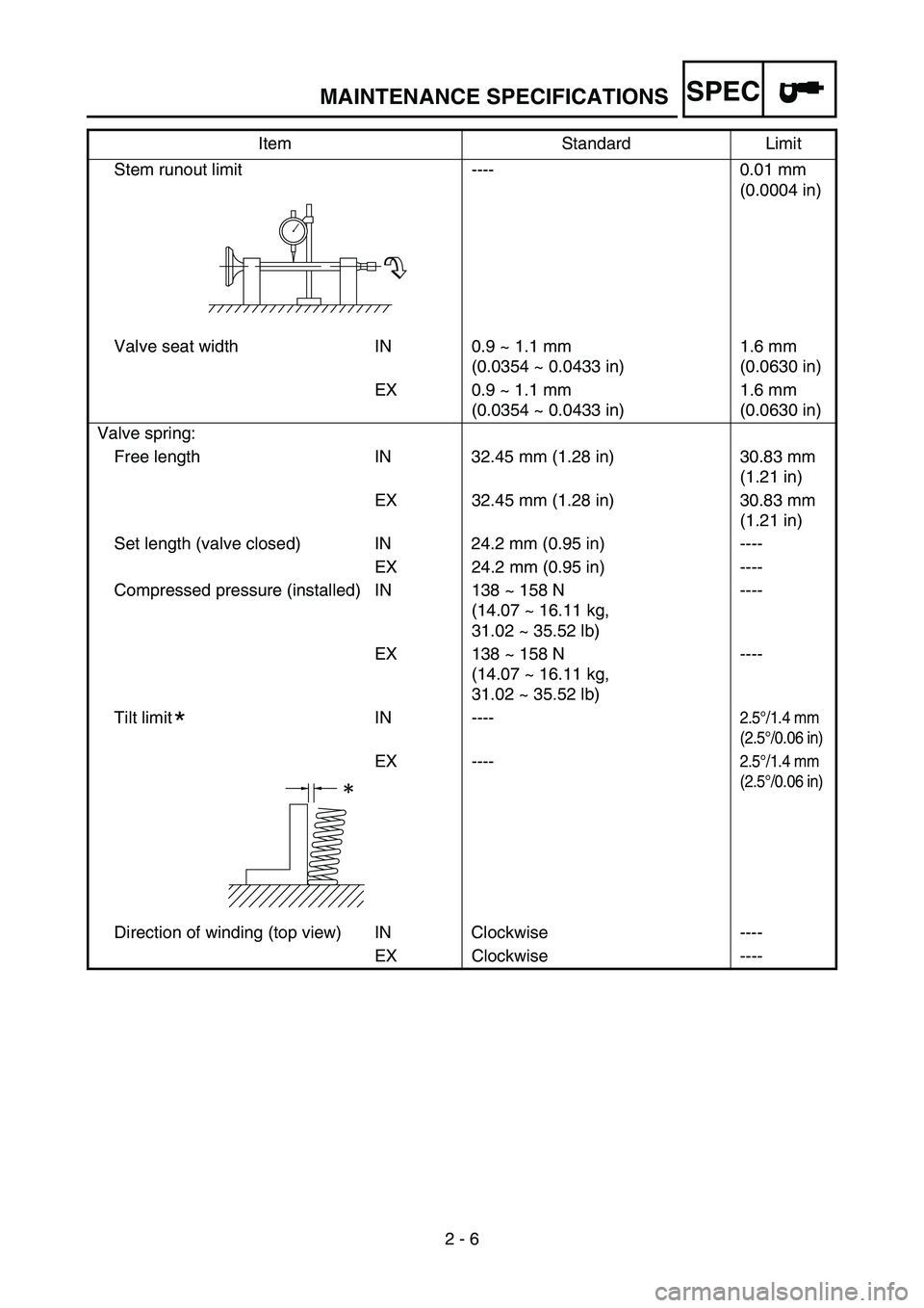
Valve spring: Free length IN 32.45 mm (1.28 in) 30.83 mm (1.21 in)
EX 32.45 mm (1.28 in) 30.83 mm (1.21 in)
Set length (valve closed) IN 24.2 mm (0.95 in) ---- EX 24.2 mm (0.95 in) ----
Compressed pressure (installed) IN 138 ~ 158 N (14.07 ~ 16.11 kg,
31.02 ~ 35.52 lb)----
EX 138 ~ 158 N (14.07 ~ 16.11 kg,
31.02 ~ 35.52 lb) ----
Tilt limit IN ----
2.5 °/1.4 mm
(2.5 °/0.06 in)
EX ----2.5 °/1.4 mm
(2.5 °/0.06 in)
Direction of winding (top view) IN Clockwise ----
EX Clockwise ----
Item Standard Limit
*
MAINTENANCE SPECIFICATIONS
Page 63 of 390

SPEC
2 - 8
Oil ring
Dimensions (B × T) 1.50 × 1.60 mm
(0.059 × 0.063 in) ----
End gap (installed) 0.20 ~ 0.70 mm (0.008 ~ 0.028 in)----
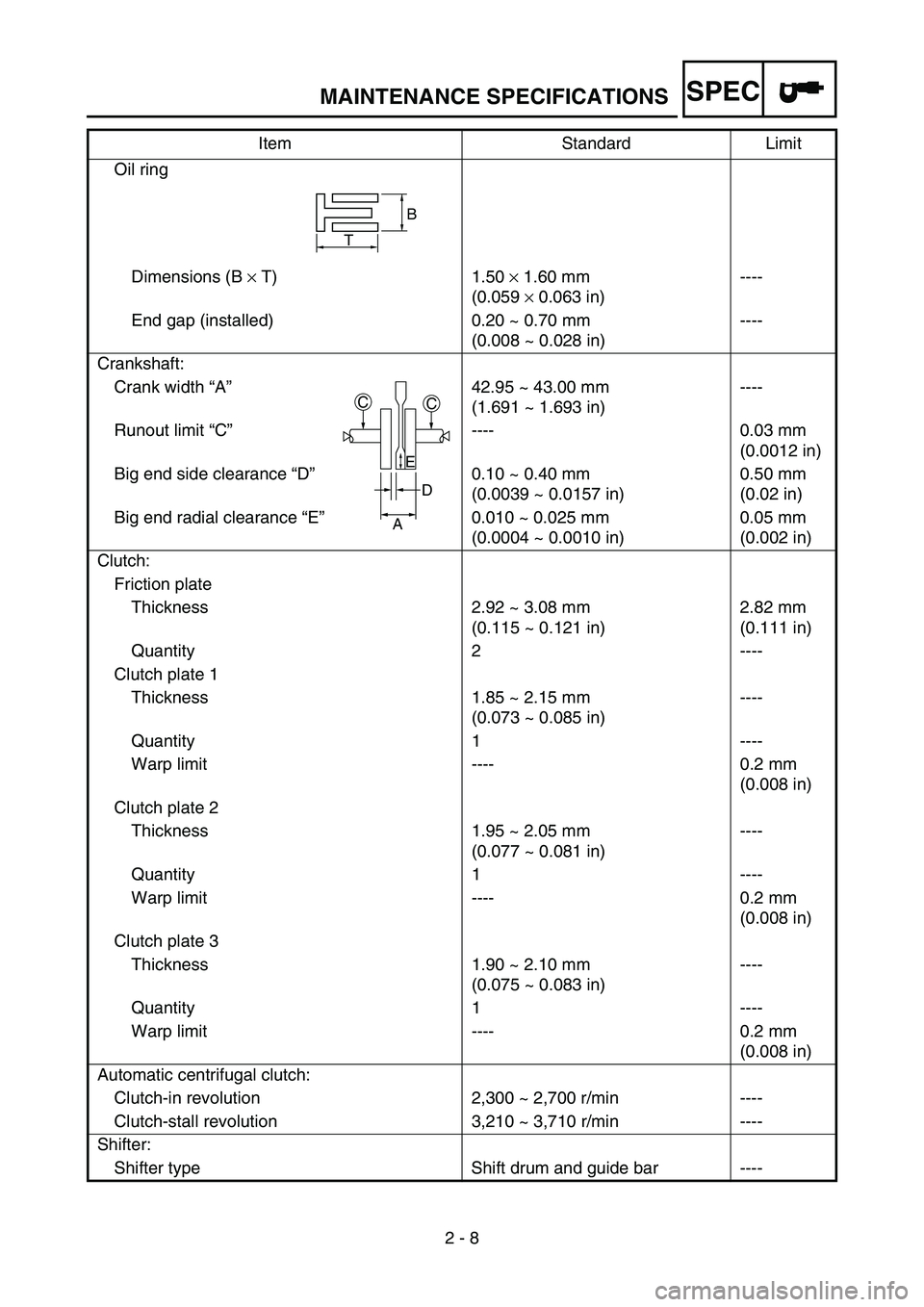
Crankshaft: Crank width “A” 42.95 ~ 43.00 mm (1.691 ~ 1.693 in)----
Runout limit “C” ---- 0.03 mm (0.0012 in)
Big end side clearance “D” 0.10 ~ 0.40 mm (0.0039 ~ 0.0157 in)0.50 mm
(0.02 in)
Big end radial clearance “E” 0.010 ~ 0.025 mm (0.0004 ~ 0.0010 in)0.05 mm
(0.002 in)
Clutch: Friction plate Thickness 2.92 ~ 3.08 mm (0.115 ~ 0.121 in)2.82 mm
(0.111 in)
Quantity 2 ----
Clutch plate 1 Thickness 1.85 ~ 2.15 mm (0.073 ~ 0.085 in)----
Quantity 1 ----
Warp limit ---- 0.2 mm (0.008 in)
Clutch plate 2 Thickness 1.95 ~ 2.05 mm (0.077 ~ 0.081 in)----
Quantity 1 ----
Warp limit ---- 0.2 mm (0.008 in)
Clutch plate 3 Thickness 1.90 ~ 2.10 mm (0.075 ~ 0.083 in)----
Quantity 1 ----
Warp limit ---- 0.2 mm (0.008 in)
Automatic centrifugal clutch: Clutch-in revolution 2,300 ~ 2,700 r/min ----
Clutch-stall revolution 3,210 ~ 3,710 r/min ----
Shifter: Shifter type Shift drum and guide bar ---- Item Standard Limit
B
T
CC
D
A
E
MAINTENANCE SPECIFICATIONS
Page 226 of 390

4 - 20
ENGVALVES AND VALVE SPRINGS
Valve spring
1. Measure:Valve spring free length a
Out of specification → Replace.
2. Measure: Spring tilt a
Out of specification → Replace.
Free length (valve spring):
Intake: 32.45 mm (1.28 in)
Exhaust: 32.45 mm (1.28 in)
Spring tilt limit:Intake: 2.5 °/1.4 mm (0.06 in)
Exhaust: 2.5 °/1.4 mm (0.06 in)
Valve seat
1. Measure:
Valve seat width a
Out of specification → Reface the valve
seat.
Valve seat width: Intake: 0.9 ~ 1.1 mm (0.0354 ~ 0.0433 in)
Exhaust: 0.9 ~ 1.1 mm (0.0354 ~ 0.0433 in)
Measurement steps:
Apply Mechanic ’s blueing dye (Dykem) b
to the valve face.
Install the valve into the cylinder head.
Press the valve through the valve guide
and onto the valve seat to make a clear
pattern.
Measure the valve seat width. Where the
valve seat and valve face made contact,
blueing will have been removed.
If the valve seat is too wide, too narrow, or
the seat is not centered, the valve seat
must be refaced.
Page 228 of 390

4 - 21
ENGVALVES AND VALVE SPRINGS
2. Lap:Valve face
Valve seat
NOTE:
After refacing the valve seat or replacing the
valve and valve guide, the valve seat and
valve face should be lapped.
Lapping steps:
Apply a coarse lapping compound to the
valve face.
CAUTION:
Do not let the compound enter the gap
between the valve stem and the guide.
Apply molybdenum disulfide oil to the
valve stem.
Install the valve into the cylinder head.
Turn the valve until the valve face and
valve seat are evenly polished, then clean
off all of the compound.
NOTE:
For best lapping results, lightly tap the valve
seat while rotating the valve back and forth
between your hands.
Apply a fine lapping compound to the
valve face and repeat the above steps.
NOTE:
After every lapping operation be sure to
clean off all of the compound from the valve
face and valve seat.
Apply Mechanic ’s blueing dye (Dykem) to
the valve face.
Install the valve into the cylinder head.
Press the valve through the valve guide
and onto the valve seat to make a clear
pattern.
Measure the valve seat width again. If the
valve seat width is out of specification,
reface and relap the valve seat.
Page 292 of 390

4 - 53
ENGCRANKCASE AND CRANKSHAFT
INSPECTION
Crankshaft
1. Measure:Runout limit a
Connecting rod big end side clearance b
Connecting rod big end radial clearance
c
Crank width d
Out of specification → Replace.
Use the dial gauge and a thickness
gauge.
Standard Limit
Runout
limit —0.03 mm
(0.0012 in)
Side
clearance 0.10 ~ 0.40 mm
(0.0039 ~ 0.0157 in) 0.50 mm
(0.02 in)
Radial
clearance 0.010 ~ 0.025 mm
(0.0004 ~ 0.0010 in) 0.05 mm
(0.002 in)
Crack
width 42.95 ~ 43.00 mm
(1.691 ~ 1.693 in) —
ASSEMBLY AND INSTALLATION
Crankcase
1. Apply:
Sealant
On the left crankcase.
NOTE:
Clean the contacting surface of crankcase
(left and right) before applying the sealant.
DO NOT ALLOW any sealant to come in
contact with the oil gallery a.
Yamaha bond No. 1215:
90890-85505
a