seat adjustment YAMAHA TTR50 2013 Owners Manual
[x] Cancel search | Manufacturer: YAMAHA, Model Year: 2013, Model line: TTR50, Model: YAMAHA TTR50 2013Pages: 86, PDF Size: 1.8 MB
Page 9 of 86

TABLE OF CONTENTS
LOCATION OF IMPORTANT
LABELS ............................................1-1
SAFETY INFORMATION .................. 2-1
DESCRIPTION .................................. 3-1
Left view .......................................... 3-1
Right view ........................................ 3-2
Controls and instruments ................3-3
INSTRUMENT AND CONTROL
FUNCTIONS ....................................... 4-1
Main switch ..................................... 4-1
Handlebar switches ........................ 4-1
Speed limiter .................................. 4-2
Shift pedal ......................................4-3
Brake lever ..................................... 4-3
Brake pedal .................................... 4-3
Fuel tank cap .................................. 4-4
Fuel ................................................ 4-4
Fuel tank breather hose ................. 4-7
Fuel cock ........................................ 4-7
Starter (choke) lever ....................... 4-8
Seat ................................................ 4-8
Sidestand ....................................... 4-9
Starting circuit cut-off system ......... 4-9 FOR YOUR SAFETY –
PRE-OPERATION CHECKS
............. 5-1
OPERATION AND IMPORTANT
RIDING POINTS ................................ 6-1
Starting and warming up a cold engine ......................................... 6-1
Starting a warm engine .................. 6-2
Shifting ........................................... 6-2
Engine break-in .............................. 6-3
Parking ........................................... 6-4
PERIODIC MAINTENANCE AND
ADJUSTMENT ................................... 7-1
Periodic maintenance chart for the emission control system ............. 7-2
General maintenance and
lubrication chart .......................... 7-3
Checking the spark plug ................ 7-6
Engine oil ....................................... 7-7
Cleaning the air filter element ........ 7-8
Cleaning the spark arrester ......... 7-10
Adjusting the carburetor ............... 7-11
Adjusting the engine idling speed ........................................ 7-11
Checking the throttle grip free
play ........................................... 7-12
Valve clearance ........................... 7-12
Tires ............................................. 7-13
Spoke wheels .............................. 7-14
Adjusting the clutch free play ....... 7-15 Adjusting the brake lever free
play ........................................... 7-15
Adjusting the brake pedal free play ........................................... 7-16
Checking the shift pedal ............... 7-17
Checking the front and rear brake
shoes ........................................ 7-17
Drive chain slack .......................... 7-18
Cleaning and lubricating the drive
chain ......................................... 7-19
Checking and lubricating the
cables ....................................... 7-20
Checking and lubricating the throttle grip and cable ............... 7-20
Checking and lubricating the brake lever ................................ 7-20
Checking and lubricating the
brake pedal ............................... 7-21
Checking and lubricating the sidestand .................................. 7-21
Lubricating the swingarm pivots ... 7-21
Checking the front fork ................. 7-22
Checking the steering .................. 7-22
Checking the wheel bearings ....... 7-23
Battery .......................................... 7-23
Replacing the fuse ....................... 7-24
Supporting the motorcycle ........... 7-25
Front wheel .................................. 7-26
Rear wheel ................................... 7-28
Troubleshooting ........................... 7-29
Troubleshooting chart .................. 7-31
U2CJ80E0.book Page 1 Tuesday, June 12, 2012 11:15 AM
Page 52 of 86

PERIODIC MAINTENANCE AND ADJUSTMENT
7-9
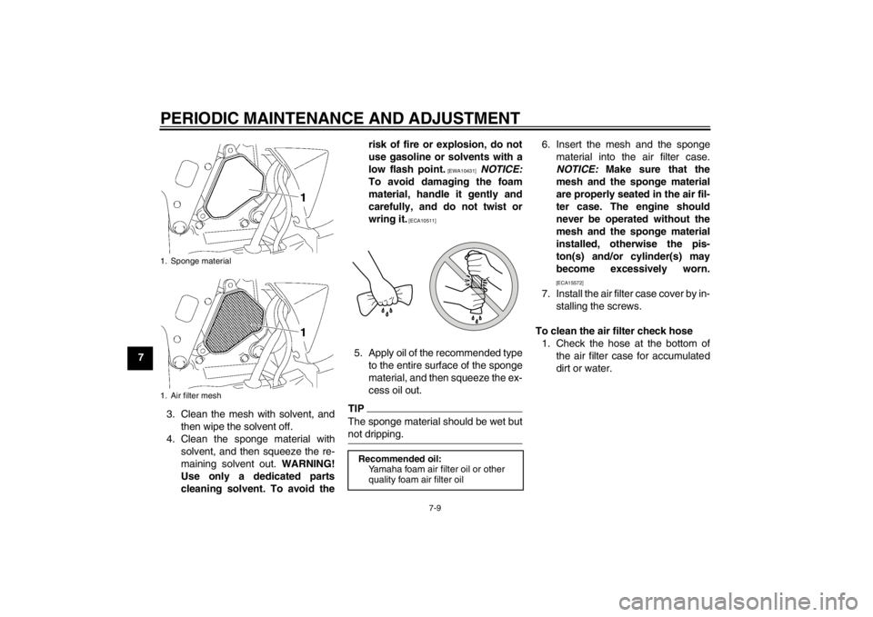
73. Clean the mesh with solvent, andthen wipe the solvent off.
4. Clean the sponge material with solvent, and then squeeze the re-
maining solvent out. WARNING!
Use only a dedicated parts
cleaning solvent. To avoid the risk of fire or explosion, do not
use gasoline or solvents with a
low flash point.
[EWA10431]
NOTICE:
To avoid damaging the foam
material, handle it gently and
carefully, and do not twist or
wring it.
[ECA10511]
5. Apply oil of the recommended type to the entire surface of the sponge
material, and then squeeze the ex-
cess oil out.TIPThe sponge material should be wet but
not dripping.
6. Insert the mesh and the spongematerial into the air filter case.
NOTICE: Make sure that the
mesh and the sponge material
are properly seated in the air fil-
ter case. The engine should
never be operated without the
mesh and the sponge material
installed, otherwise the pis-
ton(s) and/or cylinder(s) may
become excessively worn.
[ECA15572]
7. Install the air filter case cover by in- stalling the screws.
To clean the air filter check hose 1. Check the hose at the bottom of the air filter case for accumulated
dirt or water.
1. Sponge material
1. Air filter mesh
Recommended oil:Yamaha foam air filter oil or other
quality foam air filter oil
U2CJ80E0.book Page 9 Tuesday, June 12, 2012 11:15 AM
Page 57 of 86

PERIODIC MAINTENANCE AND ADJUSTMENT
7-14
7
WARNING
EWA15541
●
Have a Yamaha dealer replace
excessively worn tires. Operat-
ing the motorcycle with exces-
sively worn tires decreases
riding stability and can lead to
loss of control.
●
The replacement of all wheel-
and brake-related parts, includ-
ing the tires, should be left to a
Yamaha dealer, who has the necessary professional knowl-
edge and experience.
●
It is not recommended to patch
a punctured tube. If unavoid-
able, however, patch the tube very carefully and replace it as
soon as possible with a high-
quality product.
●
Ride conservatively after
changing a tire since the tire
must seat itself on the rim prop-
erly. Failure to allow proper
seating may cause tire failure,
which may result in damage to
the motorcycle and injury to the
rider.
EAU21943
Spoke wheels
WARNING
EWA10610
The wheels on this model are not de-
signed for use with tubeless tires.
Do not attempt to use tubeless tires
on this model.To maximize the performance, durabil-
ity, and safe operation of your motorcy-
cle, note the following points regarding
the specified wheels.●
The wheel rims should be checked
for cracks, bends, warpage or oth-
er damage, and the spokes for
looseness or damage before each
ride. If any damage is found, have
a Yamaha dealer replace the
wheel. Do not attempt even the
smallest repair to the wheel. A de-
formed or cracked wheel must be
replaced.
●
The wheel should be balanced
whenever either the tire or wheel
has been changed or replaced. An
unbalanced wheel can result in
poor performance, adverse han-
dling characteristics, and a short-
ened tire life.
Front tire:
Size:
2.50-10 4PR
Manufacturer/model:
CHENG SHIN/C183A
Rear tire: Size:
2.50-10 4PR
Manufacturer/model: CHENG SHIN/C183A
U2CJ80E0.book Page 14 Tuesday, June 12, 2012 11:15 AM
Page 66 of 86

PERIODIC MAINTENANCE AND ADJUSTMENT
7-23
7
EAU23291
Checking the wheel bearings The front and rear wheel bearings must
be checked at the intervals specified in
the periodic maintenance and lubrica-
tion chart. If there is play in the wheel
hub or if the wheel does not turn
smoothly, have a Yamaha dealer check
the wheel bearings.
EAU40446
Battery The battery is located under the seat.
(See page 4-8.)
This model is equipped with a VRLA
(Valve Regulated Lead Acid) battery.
There is no need to check the electro-
lyte or to add distilled water. However,
the battery coupler connection needs to
be checked to make sure that it is se-
curely connected.
WARNING
EWA10760
●
Electrolyte is poisonous and
dangerous since it contains sul-
furic acid, which causes severe
burns. Avoid any contact withskin, eyes or clothing and al-
ways shield your eyes when
working near batteries. In case
of contact, administer the fol-
lowing FIRST AID.
EXTERNAL: Flush with plenty of water.
INTERNAL: Drink large quan- tities of water or milk and im-
mediately call a physician.
EYES: Flush with water for 15 minutes and seek prompt
medical attention.
●
Batteries produce explosive hy-
drogen gas. Therefore, keep
sparks, flames, cigarettes, etc.,
away from the battery and pro-
vide sufficient ventilation when
charging it in an enclosed
space.
●
KEEP THIS AND ALL BATTER-
IES OUT OF THE REACH OF
CHILDREN.
To charge the battery
Have a Yamaha dealer charge the bat-
tery as soon as possible if it seems to
have discharged. Keep in mind that the
1. Battery
2. Battery coupler
1
2
U2CJ80E0.book Page 23 Tuesday, June 12, 2012 11:15 AM
Page 67 of 86

PERIODIC MAINTENANCE AND ADJUSTMENT
7-24
7
battery tends to discharge more quickly
if the vehicle is equipped with optional
electrical accessories.
NOTICE
ECA16521
To charge a VRLA (Valve Regulated
Lead Acid) battery, a special (con-
stant-voltage) battery charger is re-
quired. Using a conventional battery
charger will damage the battery.To store the battery
1. If the vehicle will not be used for more than one month, remove the
battery, fully charge it, and then
place it in a cool, dry place.
NOTICE: When removing the
battery, be sure the key is
turned to “OFF” before discon-
necting the coupler.
[ECA16322]
2. If the battery will be stored for more than two months, check it at least
once a month and fully charge it if
necessary.
3. Fully charge the battery before in- stallation. NOTICE: When install-
ing the battery, be sure the key
is turned to “OFF” before con-
necting the coupler.
[ECA16930]
NOTICE
ECA16530
Always keep the battery charged.
Storing a discharged battery can
cause permanent battery damage.
EAU42024
Replacing the fuse The fuse is located inside the battery
coupler.
If the fuse is blown, replace it as fol-
lows. 1. Turn the key to “OFF” and turn off all electrical circuits.
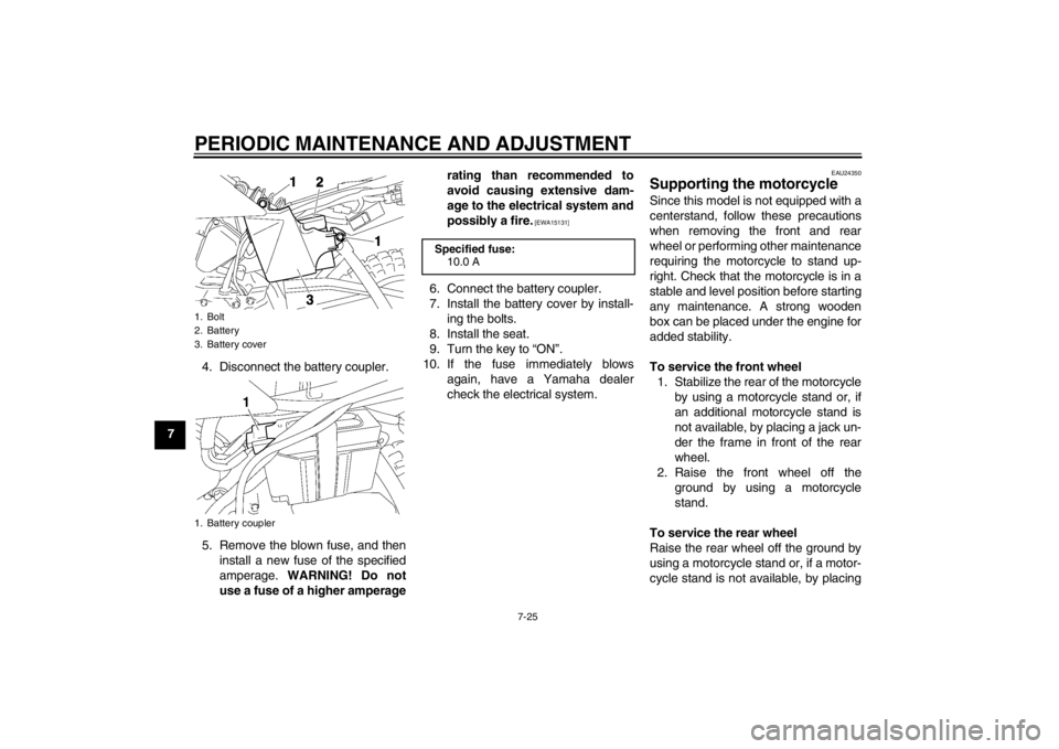
2. Remove the seat. (See page 4-8.)
3. Remove the battery cover by re- moving the bolts.1. Battery coupler
2. Spare fuse
3. Fuse
32
1
U2CJ80E0.book Page 24 Tuesday, June 12, 2012 11:15 AM
Page 68 of 86

PERIODIC MAINTENANCE AND ADJUSTMENT
7-25
74. Disconnect the battery coupler.
5. Remove the blown fuse, and then
install a new fuse of the specified
amperage. WARNING! Do not
use a fuse of a higher amperage rating than recommended to
avoid causing extensive dam-
age to the electrical system and
possibly a fire.
[EWA15131]
6. Connect the battery coupler.
7. Install the battery cover by install-
ing the bolts.
8. Install the seat.
9. Turn the key to “ON”.
10. If the fuse immediately blows again, have a Yamaha dealer
check the electrical system.
EAU24350
Supporting the motorcycle Since this model is not equipped with a
centerstand, follow these precautions
when removing the front and rear
wheel or performing other maintenance
requiring the motorcycle to stand up-
right. Check that the motorcycle is in a
stable and level position before starting
any maintenance. A strong wooden
box can be placed under the engine for
added stability.
To service the front wheel1. Stabilize the rear of the motorcycle by using a motorcycle stand or, if
an additional motorcycle stand is
not available, by placing a jack un-
der the frame in front of the rear
wheel.
2. Raise the front wheel off the ground by using a motorcycle
stand.
To service the rear wheel
Raise the rear wheel off the ground by
using a motorcycle stand or, if a motor-
cycle stand is not available, by placing
1. Bolt
2. Battery
3. Battery cover
1. Battery coupler
1
Specified fuse: 10.0 A
U2CJ80E0.book Page 25 Tuesday, June 12, 2012 11:15 AM