diagram YAMAHA TTR90 2000 Betriebsanleitungen (in German)
[x] Cancel search | Manufacturer: YAMAHA, Model Year: 2000, Model line: TTR90, Model: YAMAHA TTR90 2000Pages: 287, PDF-Größe: 6.77 MB
Page 16 of 287
EC083000
MANUAL FORMAT
All of the procedures in this manual are organized in a sequential, step-by-step format. The informa-
tion has been complied to provide the mechanic with an easy to read, handy reference that contains
comprehensive explanations of all disassembly, repair, assembly, and inspection operations.
In this revised format, the condition of a faulty component will precede an arrow symbol and the
course of action required will follow the symbol, e.g.
l
Bearings
Pitting/damage
®
Replace.
EC084002
HOW TO READ DESCRIPTIONS
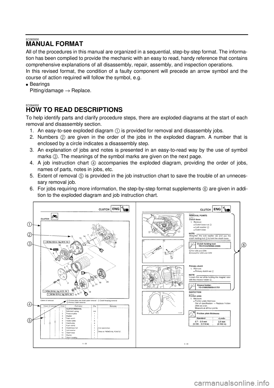
To help identify parts and clarify procedure steps, there are exploded diagrams at the start of each
removal and disassembly section.
1. An easy-to-see exploded diagram
1
is provided for removal and disassembly jobs.
2. Numbers
2
are given in the order of the jobs in the exploded diagram. A number that is
enclosed by a circle indicates a disassembly step.
3. An explanation of jobs and notes is presented in an easy-to-read way by the use of symbol
marks
3
. The meanings of the symbol marks are given on the next page.
4. A job instruction chart
4
accompanies the exploded diagram, providing the order of jobs,
names of parts, notes in jobs, etc.
5. Extent of removal
5
is provided in the job instruction chart to save the trouble of an unneces-
sary removal job.
6. For jobs requiring more information, the step-by-step format supplements
6
are given in addi-
tion to the exploded diagram and job instruction chart.
Page 17 of 287

AUFBAU
Diese Anleitung wurde zusammengestellt, um
dem Benutzer ein leicht verständliches Nach-
schlagewerk in die Hand zu geben, in dem alle
dargestellten Arbeitsvorgänge (Ein- und Aus-
bau, Zerlegung und Zusammenbau, Prüfung
und Reparatur) detailliert und in der entspre-
chenden Reihenfolge beschrieben sind.
Je nach Zustand eines fehlerhaften Bauteils
weist ein Pfeilsymbol auf die erforderliche
Maßnahme hin. Beispiel:
l
Lager
Pitting/Beschädigung
®
Erneuern.
LESEN DER BESCHREIBUNGEN
Um bei der Identifikation der Teile zu helfen
und die Arbeitsschritte zu verdeutlichen, sind
Explosionsdiagramme am Beginn jedes Aus-
bau- und Demontageabschnittes dargestellt.
1. Für die Ausbau- und Demontagearbeiten
ist meistens ein übersichtliches Explosi-
onsdiagramm
1
dargestellt.
2. Die Nummern
2
in dem Explosionsdia-
gramm sind in der Reihenfolge der Arbei-
ten aufgeführt. Eine in einen Kreis
eingeschriebene Nummer bezeichnet
einen Demontageschritt.
3. Eine Erläuterung der Arbeiten und Hin-
weise ist durch ablesefreundliche Symbol-
markierungen
3
gegeben. Die
Bedeutungen der Symbolmarkierungen
sind auf der nächsten Seite aufgeführt.
4. Eine Arbeitsanweisungstabelle
4
beglei-
tet das Explosionsdiagramm und gibt die
Arbeitsreihenfolge, Bezeichnung der Teile,
Hinweise zu den Arbeiten usw. an.
5. Der Umfang des Ausbaus
5
ist in der
Arbeitsanweisungstabelle aufgeführt, um
nicht erforderliche Ausbauarbeiten zu ver-
meiden.
6. Für Arbeiten, für die weitere Informationen
benötigt werden, sind schrittweise Ergän-
zungen
6
zusätzlich zu dem Explosions-
diagramm und der
Arbeitsanweisungstabelle aufgeführt.
FORMAT DU MANUEL
Dans ce manuel, toutes les procédures sont décrites
pas à pas. Les informations ont été condensées pour
fournir à l’utilisateur un guide pratique et facile à
lire, contenant des explications claires pour toutes
les procédures de démontage, réparation, remon-
tage et vérification.
Dans ce nouveau format, l’état d’un composant
défectueux est suivi d’une flèche qui indique les
mesures à prendre. Exemple:
l
Roulements
Piqûres/endommagement
®
Remplacer.
COMMENT LIRE LES DESCRIP-
TIONS
Chaque section détaillant des étapes de démontage
ou de remontage est précédée de vues en éclaté qui
permettent de clarifier ces opérations.
1. Exemple de vue en éclaté
1
clarifiant les opé-
rations de démontage et de remontage.
2. Sur les vues en éclaté, les pièces sont numéro-
tées
2
dans l’ordre des opérations à effectuer.
Un chiffre entouré d’un cercle correspond à une
étape de démontage.
3. Les vues en éclaté portent également des sym-
boles
3 qui rappellent des points importants à
ne pas oublier. La signification de ces symboles
est expliquée à la page suivante.
4. Les vues en éclaté sont suivies d’un tableau 4
fournissant l’ordre des opérations, le nom des
pièces, des remarques, etc.
5. Pour éviter la dépose superflue de pièces,
l’étendue de la dépose 5 est indiquée dans le
tableau de description du travail.
6. Pour les travaux qui demandent des explica-
tions supplémentaires, la vue en éclaté et le
tableau sont suivis d’une description détaillée
6 des opérations.
Page 18 of 287
EC085001
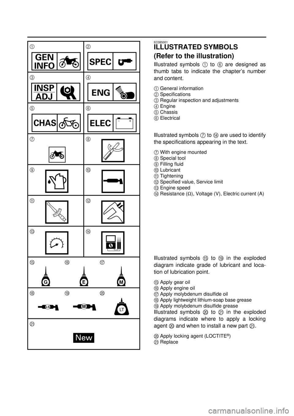
ILLUSTRATED SYMBOLS
(Refer to the illustration)
Illustrated symbols
1
to
6
are designed as
thumb tabs to indicate the chapter’s number
and content.
1
General information
2
Specifications
3
Regular inspection and adjustments
4
Engine
5
Chassis
6
Electrical
Illustrated symbols
7
to
D
are used to identify
the specifications appearing in the text.
7
With engine mounted
8
Special tool
9
Filling fluid
0
Lubricant
A
Tightening
B
Specified value, Service limit
C
Engine speed
DResistance (W), Voltage (V), Electric current (A)
Illustrated symbols E to I in the exploded
diagram indicate grade of lubricant and loca-
tion of lubrication point.
EApply gear oil
FApply engine oil
GApply molybdenum disulfide oil
HApply lightweight lithium-soap base grease
IApply molybdenum disulfide grease
Illustrated symbols J to K in the exploded
diagrams indicate where to apply a locking
agent J and when to install a new part K.
JApply locking agent (LOCTITE®)
KReplace 12
34
56
78
90
AB
CD
EFG
HIJ
K
GEN
INFOSPEC
INSP
ADJENG
CHAS–+ELEC
T R..
GME
MLTLS
New
Page 22 of 287

CONTENTS
CHAPTER 1
GENERAL INFORMATION
DESCRIPTION
.......................................... 1-1
MACHINE IDENTIFICATION
.................... 1-2
IMPORTANT INFORMATION
................... 1-3
CHECKING OF CONNECTION
................ 1-5
SPECIAL TOOLS
...................................... 1-6
CONTROL FUNCTIONS
........................... 1-9
FUEL
....................................................... 1-11
STARTING AND OPERATION
............... 1-12
CHAPTER 2
SPECIFICATIONS
GENERAL SPECIFICATIONS
................... 2-1
MAINTENANCE SPECIFICATIONS
......... 2-4
GENERAL TORQUE
SPECIFICATIONS
.................................. 2-15
DEFINITION OF UNITS
.......................... 2-15
CABLE ROUTING DIAGRAM
................ 2-16
CHAPTER 3
REGULAR INSPECTION AND
ADJUSTMENTS
MAINTENANCE INTERVALS
................... 3-1
PERIODIC MAINTENANCE AND
LUBRICATION
.......................................... 3-1
PRE-OPERATION INSPECTION AND
MAINTENANCE
........................................ 3-2
ENGINE
..................................................... 3-3
CHASSIS
................................................. 3-11
ELECTRICAL
.......................................... 3-19
Page 24 of 287

CHAPTER 4
ENGINE
CARBURETOR
......................................... 4-1
CYLINDER HEAD
..................................... 4-8
CAMSHAFT AND ROCKER ARMS
....... 4-13
VALVES AND VALVE SPRINGS
........... 4-16
CYLINDER AND PISTON
....................... 4-21
CLUTCH
.................................................. 4-27
KICK AXLE
............................................. 4-33
SHIFT SHAFT
......................................... 4-34
OIL PUMP
............................................... 4-36
CDI MAGNETO
....................................... 4-39
CRANKCASE AND CRANKSHAFT
....... 4-41
SHIFT FORK, SHIFT CAM AND
TRANSMISSION
..................................... 4-44
CHAPTER 5
CHASSIS
FRONT WHEEL AND REAR WHEEL
...... 5-1
FRONT FORK
........................................... 5-6
HANDLEBAR
............................................ 5-9
STEERING
.............................................. 5-10
SWINGARM
............................................ 5-11
CHAPTER 6
ELECTRICAL
ELECTRICAL COMPONENTS AND
WIRING DIAGRAM
................................... 6-1
IGNITION SYSTEM
................................... 6-2
CARBURETOR HEATING SYSTEM
........ 6-6
MAINTENANCE RECORD
....................... 6-9
Page 102 of 287
2 - 16
SPEC
CABLE ROUTING DIAGRAM
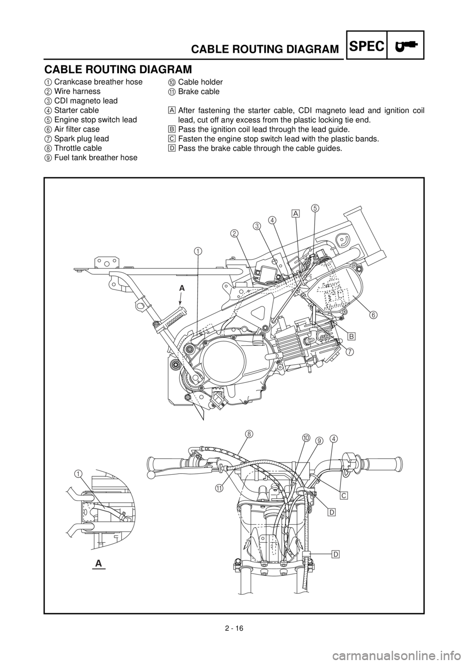
CABLE ROUTING DIAGRAM
1
Crankcase breather hose
2
Wire harness
3
CDI magneto lead
4
Starter cable
5
Engine stop switch lead
6
Air filter case
7
Spark plug lead
8
Throttle cable
9
Fuel tank breather hose
0
Cable holder
A
Brake cable
After fastening the starter cable, CDI magneto lead and ignition coil
lead, cut off any excess from the plastic locking tie end.
õ
Pass the ignition coil lead through the lead guide.
‚
Fasten the engine stop switch lead with the plastic bands.
ë
Pass the brake cable through the cable guides.
12345
6
7
8
9 0
4
A 1
õ
‚
ë
ë
A
A
Page 104 of 287
2 - 17
SPEC
CABLE ROUTING DIAGRAM
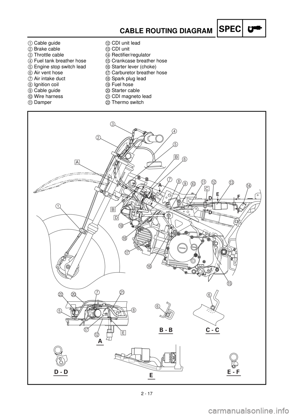
1
Cable guide
2
Brake cable
3
Throttle cable
4
Fuel tank breather hose
5
Engine stop switch lead
6
Air vent hose
7
Air intake duct
8
Ignition coil
9
Cable guide
0
Wire harness
A
Damper
B
CDI unit lead
C
CDI unit
D
Rectifier/regulator
E
Crankcase breather hose
F
Starter lever (choke)
G
Carburetor breather hose
H
Spark plug lead
I
Fuel hose
J
Starter cable
K
CDI magneto lead
L
Thermo switch
A
123
4
5
6
7
8
9
0A
C
D B
E F G H I
6
6 J L
5
G
B8 K
7 õ
‚
õ
ë
ä
B - B C - C
D - DE - FE
A A B
B B
B
C
C C
CE
B D
B D
F
F F F
Page 106 of 287
2 - 18
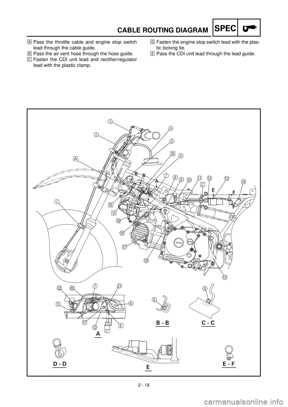
SPECCABLE ROUTING DIAGRAM
Pass the throttle cable and engine stop switch
lead through the cable guide.
õPass the air vent hose through the hose guide.
‚Fasten the CDI unit lead and rectifier/regulator
lead with the plastic clamp.ëFasten the engine stop switch lead with the plas-
tic locking tie.
äPass the CDI unit lead through the lead guide.
A
123
4
5
6
7
8
9
0A
C
D B
E F G H I
6
6 J L
5
G
B8 K
7 õ
‚
õ
ë
ä
B - B C - C
D - DE - FE
A A B
B B
B
C
C C
CE
B D
B D
F
F F F
Page 264 of 287
6 - 1
–+ELEC
ELECTRICAL COMPONENTS AND WIRING DIAGRAM
EC600000
ELECTRICAL
EC610000
ELECTRICAL COMPONENTS AND WIRING DIAGRAM
EC611000
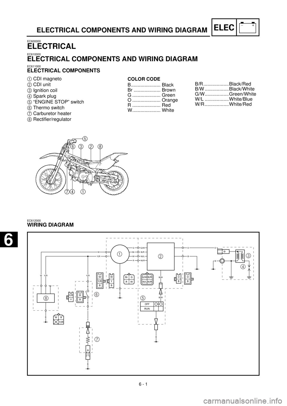
ELECTRICAL COMPONENTS
1
CDI magneto
2
CDI unit
3
Ignition coil
4
Spark plug
5
“ENGINE STOP” switch
6
Thermo switch
7
Carburetor heater
8
Rectifier/regulator
COLOR CODE
B...................... Black
Br .................... Brown
G ..................... Green
O ..................... Orange
R ..................... Red
W..................... White
EC612000
WIRING DIAGRAM
G/WB/RW/LW/RBr G
RW
WB
Y/R
O
BO
B
B
BY/RY
WY/RB
W
Y
B
GG/W
B/W
B/W
BrB/RWWWY
OO
BBW/LY/RR
W
B
B
B
W/R
Y/R
OFF
RUN
B
Y/R
B
B
Y
Y
1
23
4
5 6
7 8
B/R ................... Black/Red
B/W .................. Black/White
G/W.................. Green/White
W/L .................. White/Blue
W/R .................. White/Red
6
Page 268 of 287

–+ELEC
ZÜNDANLAGE
ZÜNDANLAGE
FEHLERSUCHE
Folgendes Diagramm hilft zündanlagen- und zündkerzenbedingte Motorstörungen zu beheben.
HINWEIS:
l
Die folgenden Teile vor Beginn der Störungsbeseitigung ausbauen.
1) Sitz
2) Kraftstofftank
l
Folgendes Spezialwerkzeug verwenden.
Zündfunkenstrecke
kontrollierenZündkerze reinigen
oder erneuern.
Kabelanschlüsse der
gesamten Zündenlage kon-
trollieren.Erneuern oder instand
setzen.
Motorstoppschalter
kontrollieren.Erneuern.
Zündspule kontrollieren. Primärspule Erneuern.
Sekundär-
spuleErneuern.
CDI-Schwungradmagnet-
zünder kontrollieren.Impulsgeber Erneuern.
Erregerspule Erneuern.
CDI-Zündbox erneuern.
Zündfunkenstreckentester
YM-34487
90890-06754
Taschen-Multimeter
YU-03112/90890-03112
Kein Zündfunke
In Ordnung
In Ordnung
In Ordnung
In Ordnung
Zündfunke
Nicht in Ordnung
Nicht in Ordnung
Nicht in Ordnung
Nicht in Ordnung
Nicht in Ordnung
Nicht in Ordnung
6 - 2