ignition YAMAHA TTR90 2000 Betriebsanleitungen (in German)
[x] Cancel search | Manufacturer: YAMAHA, Model Year: 2000, Model line: TTR90, Model: YAMAHA TTR90 2000Pages: 287, PDF-Größe: 6.77 MB
Page 24 of 287

CHAPTER 4
ENGINE
CARBURETOR
......................................... 4-1
CYLINDER HEAD
..................................... 4-8
CAMSHAFT AND ROCKER ARMS
....... 4-13
VALVES AND VALVE SPRINGS
........... 4-16
CYLINDER AND PISTON
....................... 4-21
CLUTCH
.................................................. 4-27
KICK AXLE
............................................. 4-33
SHIFT SHAFT
......................................... 4-34
OIL PUMP
............................................... 4-36
CDI MAGNETO
....................................... 4-39
CRANKCASE AND CRANKSHAFT
....... 4-41
SHIFT FORK, SHIFT CAM AND
TRANSMISSION
..................................... 4-44
CHAPTER 5
CHASSIS
FRONT WHEEL AND REAR WHEEL
...... 5-1
FRONT FORK
........................................... 5-6
HANDLEBAR
............................................ 5-9
STEERING
.............................................. 5-10
SWINGARM
............................................ 5-11
CHAPTER 6
ELECTRICAL
ELECTRICAL COMPONENTS AND
WIRING DIAGRAM
................................... 6-1
IGNITION SYSTEM
................................... 6-2
CARBURETOR HEATING SYSTEM
........ 6-6
MAINTENANCE RECORD
....................... 6-9
Page 37 of 287
GEN
INFO
1 - 7
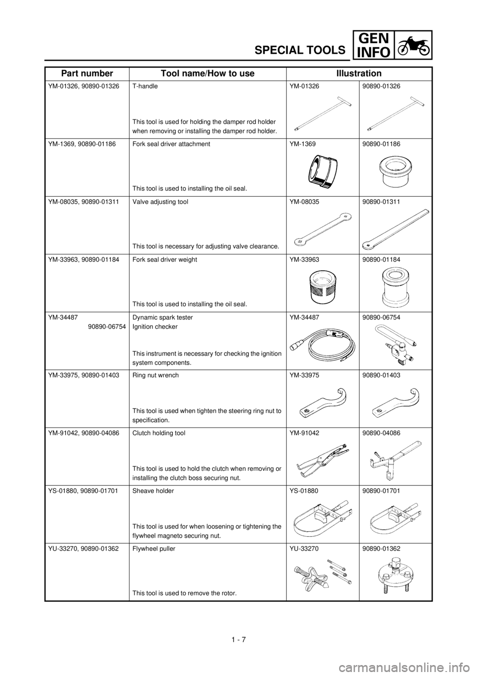
SPECIAL TOOLS
YM-01326, 90890-01326 T-handle
This tool is used for holding the damper rod holder
when removing or installing the damper rod holder.YM-01326 90890-01326
YM-1369, 90890-01186 Fork seal driver attachment
This tool is used to installing the oil seal.YM-1369 90890-01186
YM-08035, 90890-01311 Valve adjusting tool
This tool is necessary for adjusting valve clearance.YM-08035 90890-01311
YM-33963, 90890-01184 Fork seal driver weight
This tool is used to installing the oil seal.YM-33963 90890-01184
YM-34487
90890-06754Dynamic spark tester
Ignition checker
This instrument is necessary for checking the ignition
system components.YM-34487 90890-06754
YM-33975, 90890-01403 Ring nut wrench
This tool is used when tighten the steering ring nut to
specification.YM-33975 90890-01403
YM-91042, 90890-04086 Clutch holding tool
This tool is used to hold the clutch when removing or
installing the clutch boss securing nut.YM-91042 90890-04086
YS-01880, 90890-01701 Sheave holder
This tool is used for when loosening or tightening the
flywheel magneto securing nut.YS-01880 90890-01701
YU-33270, 90890-01362 Flywheel puller
This tool is used to remove the rotor.YU-33270 90890-01362
Part number Tool name/How to use Illustration
Page 58 of 287

SPEC
2 - 3
Shock absorber:
Front shock absorber Coil spring/oil damper
Rear shock absorber Coil spring/gas, oil damper
Wheel travel:
Front wheel travel 100 mm (4.33 in)
Rear wheel travel 93 mm (3.66 in)
Electrical:
Ignition system CDI magneto
GENERAL SPECIFICATIONS
Page 69 of 287

SPEC
2 - 14
EC212300
ELECTRICAL
Item Standard Limit
Ignition system:
Ignition timing (B.T.D.C.) 15˚/1,700 r/min
Advancer type Electrical ----
C.D.I.:
Magneto-model/manufacturer F5HN/YAMAHA ----
Source coil resistance (color) 688 ~ 1,032
W
at 20 ˚C (68 ˚F)
(Brown – Green)----
Pickup coil resistance (color) 248 ~ 372
W
at 20 ˚C (68 ˚F)
(Red – White)----
CDI unit-model/manufacturer 4GL/YAMAHA ----
Ignition coil:
Model/manufacturer 2JN/YAMAHA ----
Minimum spark gap 6 mm (0.24 in) ----
Primary winding resistance 0.18 ~ 0.28
W
at 20 ˚C (68 ˚F) ----
Secondary winding resistance 6.3 ~ 9.5 k
W
at 20 ˚C (68 ˚F) ----
Spark plug cap:
Type Resin ----
Resistance 10 k
W
at 20 ˚C (68 ˚F) ----
MAINTENANCE SPECIFICATIONS
Page 102 of 287
2 - 16
SPEC
CABLE ROUTING DIAGRAM
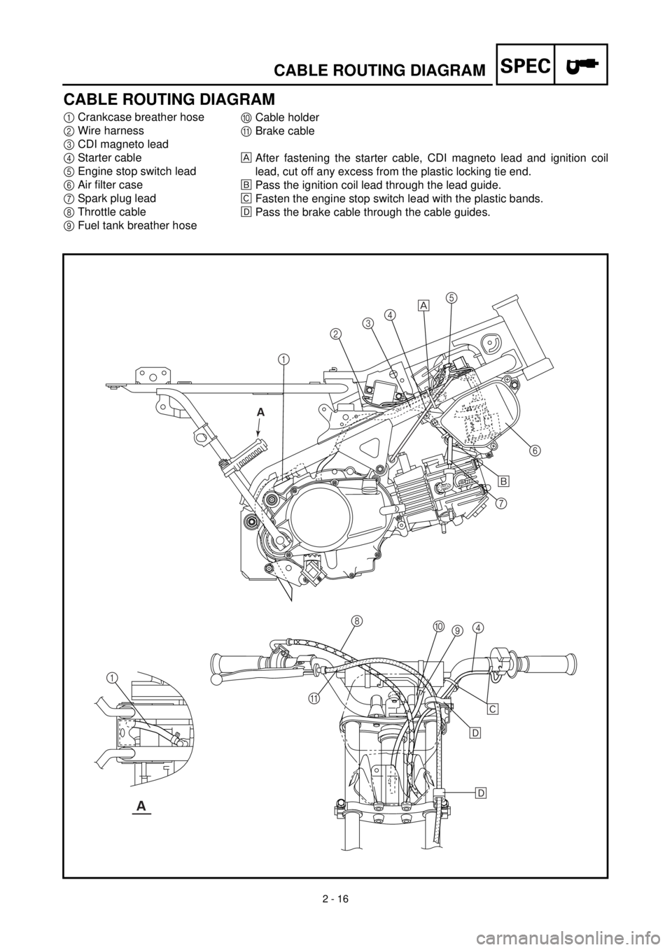
CABLE ROUTING DIAGRAM
1
Crankcase breather hose
2
Wire harness
3
CDI magneto lead
4
Starter cable
5
Engine stop switch lead
6
Air filter case
7
Spark plug lead
8
Throttle cable
9
Fuel tank breather hose
0
Cable holder
A
Brake cable
After fastening the starter cable, CDI magneto lead and ignition coil
lead, cut off any excess from the plastic locking tie end.
õ
Pass the ignition coil lead through the lead guide.
‚
Fasten the engine stop switch lead with the plastic bands.
ë
Pass the brake cable through the cable guides.
12345
6
7
8
9 0
4
A 1
õ
‚
ë
ë
A
A
Page 104 of 287
2 - 17
SPEC
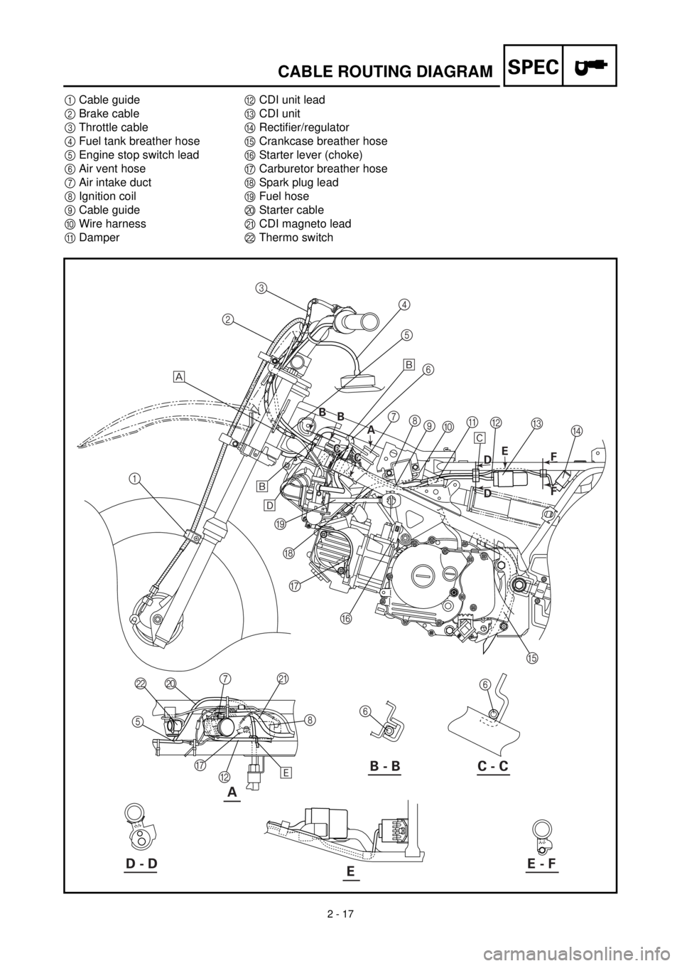
CABLE ROUTING DIAGRAM
1
Cable guide
2
Brake cable
3
Throttle cable
4
Fuel tank breather hose
5
Engine stop switch lead
6
Air vent hose
7
Air intake duct
8
Ignition coil
9
Cable guide
0
Wire harness
A
Damper
B
CDI unit lead
C
CDI unit
D
Rectifier/regulator
E
Crankcase breather hose
F
Starter lever (choke)
G
Carburetor breather hose
H
Spark plug lead
I
Fuel hose
J
Starter cable
K
CDI magneto lead
L
Thermo switch
A
123
4
5
6
7
8
9
0A
C
D B
E F G H I
6
6 J L
5
G
B8 K
7 õ
‚
õ
ë
ä
B - B C - C
D - DE - FE
A A B
B B
B
C
C C
CE
B D
B D
F
F F F
Page 158 of 287
4 - 6
ENGCARBURETOR
EC464600
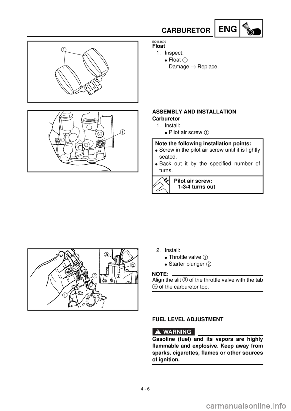
Float
1. Inspect:
lFloat 1
Damage ® Replace.
ASSEMBLY AND INSTALLATION
Carburetor
1. Install:
lPilot air screw 1
Note the following installation points:
lScrew in the pilot air screw until it is lightly
seated.
lBack out it by the specified number of
turns.
Pilot air screw:
1-3/4 turns out
2. Install:
lThrottle valve 1
lStarter plunger 2
NOTE:
Align the slit a of the throttle valve with the tab
b of the carburetor top.
FUEL LEVEL ADJUSTMENT
WARNING
Gasoline (fuel) and its vapors are highly
flammable and explosive. Keep away from
sparks, cigarettes, flames or other sources
of ignition.
Page 264 of 287
6 - 1
–+ELEC
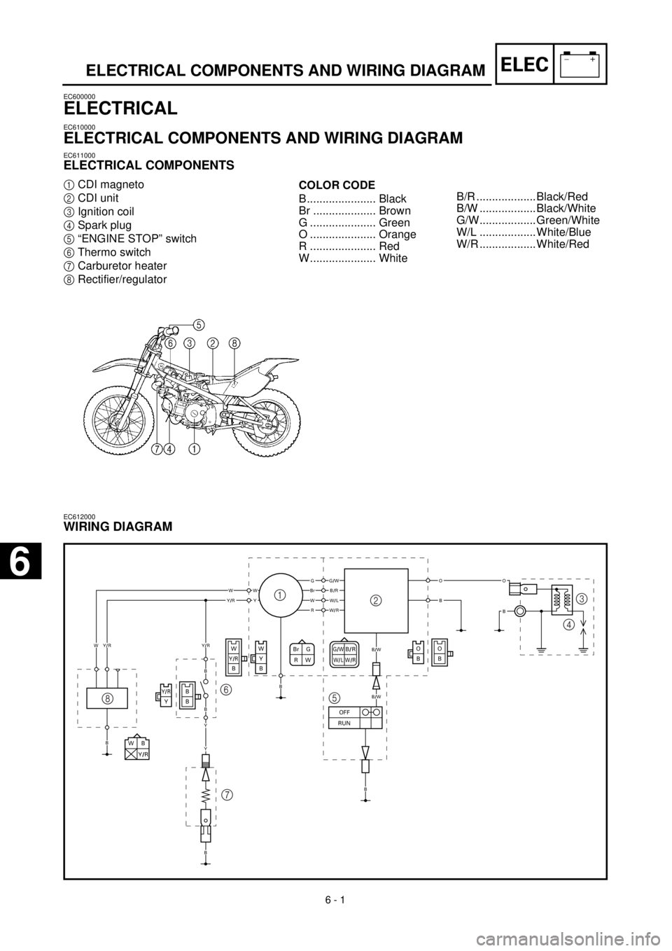
ELECTRICAL COMPONENTS AND WIRING DIAGRAM
EC600000
ELECTRICAL
EC610000
ELECTRICAL COMPONENTS AND WIRING DIAGRAM
EC611000
ELECTRICAL COMPONENTS
1
CDI magneto
2
CDI unit
3
Ignition coil
4
Spark plug
5
“ENGINE STOP” switch
6
Thermo switch
7
Carburetor heater
8
Rectifier/regulator
COLOR CODE
B...................... Black
Br .................... Brown
G ..................... Green
O ..................... Orange
R ..................... Red
W..................... White
EC612000
WIRING DIAGRAM
G/WB/RW/LW/RBr G
RW
WB
Y/R
O
BO
B
B
BY/RY
WY/RB
W
Y
B
GG/W
B/W
B/W
BrB/RWWWY
OO
BBW/LY/RR
W
B
B
B
W/R
Y/R
OFF
RUN
B
Y/R
B
B
Y
Y
1
23
4
5 6
7 8
B/R ................... Black/Red
B/W .................. Black/White
G/W.................. Green/White
W/L .................. White/Blue
W/R .................. White/Red
6
Page 266 of 287
–+ELEC
6 - 2
IGNITION SYSTEM
EC620000
IGNITION SYSTEM
EC621001
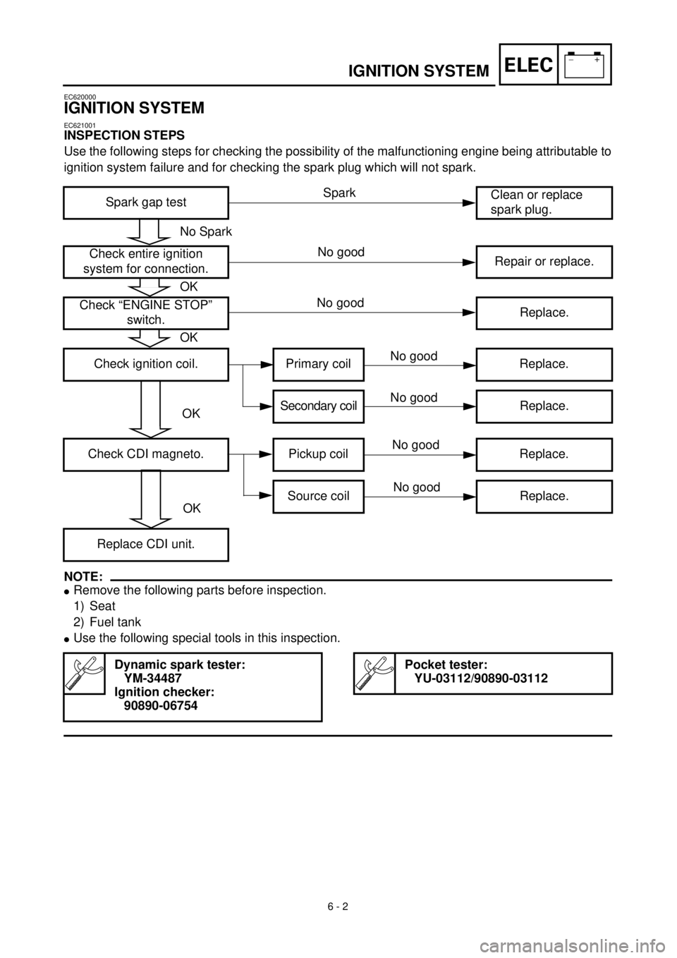
INSPECTION STEPS
Use the following steps for checking the possibility of the malfunctioning engine being attributable to
ignition system failure and for checking the spark plug which will not spark.
NOTE:
l
Remove the following parts before inspection.
1) Seat
2) Fuel tank
l
Use the following special tools in this inspection.
Spark gap testClean or replace
spark plug.
Check entire ignition
system for connection.Repair or replace.
Check “ENGINE STOP”
switch.Replace.
Check ignition coil. Primary coil Replace.
Secondary coilReplace.
Check CDI magneto. Pickup coil Replace.
Source coil Replace.
Replace CDI unit.
Dynamic spark tester:
YM-34487
Ignition checker:
90890-06754
Pocket tester:
YU-03112/90890-03112
No Spark
OK
OK
OK
OK
Spark
No good
No good
No good
No good
No good
No good
Page 270 of 287
6 - 3
–+ELEC
IGNITION SYSTEM
EC622001
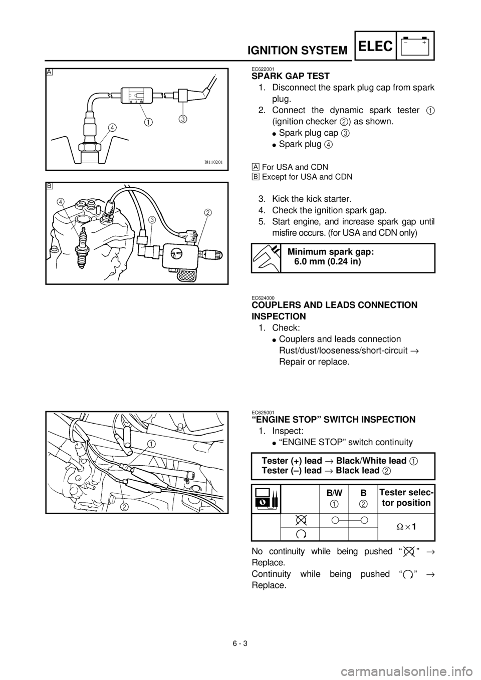
SPARK GAP TEST
1. Disconnect the spark plug cap from spark
plug.
2. Connect the dynamic spark tester
1
(ignition checker
2
) as shown.
l
Spark plug cap
3
l
Spark plug
4
For USA and CDN
õ
Except for USA and CDN
3. Kick the kick starter.
4. Check the ignition spark gap.
5. Start engine, and increase spark gap until
misfire occurs. (for USA and CDN only)
Minimum spark gap:
6.0 mm (0.24 in)
õ
EC624000
COUPLERS AND LEADS CONNECTION
INSPECTION
1. Check:
l
Couplers and leads connection
Rust/dust/looseness/short-circuit
®
Repair or replace.
EC625001
“ENGINE STOP” SWITCH INSPECTION
1. Inspect:
l
“ENGINE STOP” switch continuity
No continuity while being pushed “ ”
®
Replace.
Continuity while being pushed “ ”
®
Replace.
Tester (+) lead
®
Black/White lead
1
Tester (–) lead
®
Black lead
2
B/W
1
B
2
Tester selec-
tor position
W
´
1