wheel YAMAHA TTR90 2000 Betriebsanleitungen (in German)
[x] Cancel search | Manufacturer: YAMAHA, Model Year: 2000, Model line: TTR90, Model: YAMAHA TTR90 2000Pages: 287, PDF-Größe: 6.77 MB
Page 24 of 287

CHAPTER 4
ENGINE
CARBURETOR
......................................... 4-1
CYLINDER HEAD
..................................... 4-8
CAMSHAFT AND ROCKER ARMS
....... 4-13
VALVES AND VALVE SPRINGS
........... 4-16
CYLINDER AND PISTON
....................... 4-21
CLUTCH
.................................................. 4-27
KICK AXLE
............................................. 4-33
SHIFT SHAFT
......................................... 4-34
OIL PUMP
............................................... 4-36
CDI MAGNETO
....................................... 4-39
CRANKCASE AND CRANKSHAFT
....... 4-41
SHIFT FORK, SHIFT CAM AND
TRANSMISSION
..................................... 4-44
CHAPTER 5
CHASSIS
FRONT WHEEL AND REAR WHEEL
...... 5-1
FRONT FORK
........................................... 5-6
HANDLEBAR
............................................ 5-9
STEERING
.............................................. 5-10
SWINGARM
............................................ 5-11
CHAPTER 6
ELECTRICAL
ELECTRICAL COMPONENTS AND
WIRING DIAGRAM
................................... 6-1
IGNITION SYSTEM
................................... 6-2
CARBURETOR HEATING SYSTEM
........ 6-6
MAINTENANCE RECORD
....................... 6-9
Page 37 of 287
GEN
INFO
1 - 7
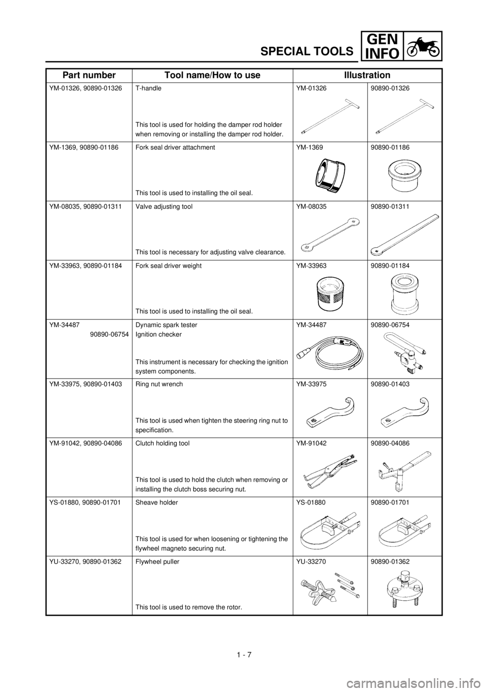
SPECIAL TOOLS
YM-01326, 90890-01326 T-handle
This tool is used for holding the damper rod holder
when removing or installing the damper rod holder.YM-01326 90890-01326
YM-1369, 90890-01186 Fork seal driver attachment
This tool is used to installing the oil seal.YM-1369 90890-01186
YM-08035, 90890-01311 Valve adjusting tool
This tool is necessary for adjusting valve clearance.YM-08035 90890-01311
YM-33963, 90890-01184 Fork seal driver weight
This tool is used to installing the oil seal.YM-33963 90890-01184
YM-34487
90890-06754Dynamic spark tester
Ignition checker
This instrument is necessary for checking the ignition
system components.YM-34487 90890-06754
YM-33975, 90890-01403 Ring nut wrench
This tool is used when tighten the steering ring nut to
specification.YM-33975 90890-01403
YM-91042, 90890-04086 Clutch holding tool
This tool is used to hold the clutch when removing or
installing the clutch boss securing nut.YM-91042 90890-04086
YS-01880, 90890-01701 Sheave holder
This tool is used for when loosening or tightening the
flywheel magneto securing nut.YS-01880 90890-01701
YU-33270, 90890-01362 Flywheel puller
This tool is used to remove the rotor.YU-33270 90890-01362
Part number Tool name/How to use Illustration
Page 56 of 287
SPEC
2 - 1
EC200000
SPECIFICATIONS
EC211000
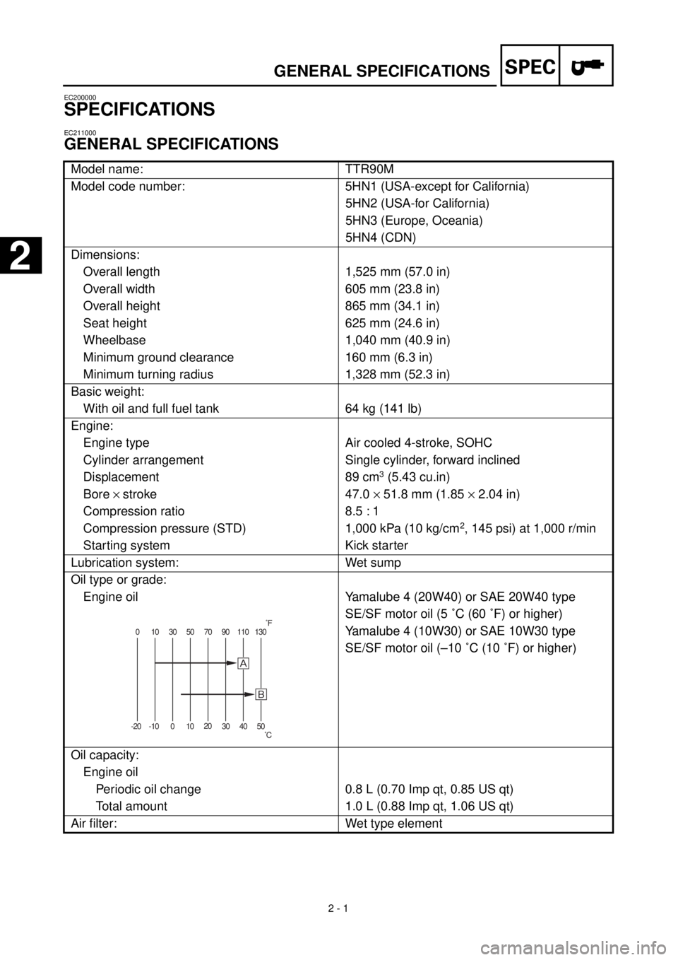
GENERAL SPECIFICATIONS
Model name: TTR90M
Model code number: 5HN1 (USA-except for California)
5HN2 (USA-for California)
5HN3 (Europe, Oceania)
5HN4 (CDN)
Dimensions:
Overall length 1,525 mm (57.0 in)
Overall width 605 mm (23.8 in)
Overall height 865 mm (34.1 in)
Seat height 625 mm (24.6 in)
Wheelbase 1,040 mm (40.9 in)
Minimum ground clearance 160 mm (6.3 in)
Minimum turning radius 1,328 mm (52.3 in)
Basic weight:
With oil and full fuel tank 64 kg (141 lb)
Engine:
Engine type Air cooled 4-stroke, SOHC
Cylinder arrangement Single cylinder, forward inclined
Displacement 89 cm
3
(5.43 cu.in)
Bore
´
stroke 47.0
´
51.8 mm (1.85
´
2.04 in)
Compression ratio 8.5 : 1
Compression pressure (STD) 1,000 kPa (10 kg/cm
2
, 145 psi) at 1,000 r/min
Starting system Kick starter
Lubrication system: Wet sump
Oil type or grade:
Engine oil
Yamalube 4 (20W40) or SAE 20W40 type
SE/SF motor oil (5 ˚C (60 ˚F) or higher)
Yamalube 4 (10W30) or SAE 10W30 type
SE/SF motor oil (–10 ˚C (10 ˚F) or higher)
Oil capacity:
Engine oil
Periodic oil change 0.8 L (0.70 Imp qt, 0.85 US qt)
Total amount 1.0 L (0.88 Imp qt, 1.06 US qt)
Air filter: Wet type element
0 10 30 50 70 90 110 130
-20 -10 01020
30 40 50
õ
˚F
˚C
GENERAL SPECIFICATIONS
2
Page 58 of 287

SPEC
2 - 3
Shock absorber:
Front shock absorber Coil spring/oil damper
Rear shock absorber Coil spring/gas, oil damper
Wheel travel:
Front wheel travel 100 mm (4.33 in)
Rear wheel travel 93 mm (3.66 in)
Electrical:
Ignition system CDI magneto
GENERAL SPECIFICATIONS
Page 66 of 287

SPEC
2 - 11
EC212201
CHASSIS
Item Standard Limit
Steering system:
Steering bearing type Taper roller bearing
Angular bearing----
Front suspension:
Front fork travel 110 mm (4.33 in) ----
Fork spring free length 425.1 mm (16.74 in) 417 mm (16.4 in)
Fork spring fitting length 415.1 mm (16.34 in) ----
Spring rate, STD K = 3.4 N/mm
(0.35 kg/mm, 19.41 lb/in)----
Optional spring/spacer No ----
Oil capacity 64 cm
3
(2.26 lmp oz, 2.16 US oz) ----
Oil level 185 mm (7.28 in) ----
Oil grade Fork oil 15W or equivalent ----
Rear suspension:
Shock absorber travel 48 mm (1.89 in) ----
Spring free length 169 mm (6.65 in) ----
Fitting length 165 mm (6.5 in) ----
Spring rate, STD K = 45.6 N/mm
(4.6 kg/mm, 260 lb/in)----
Optional spring No ----
Enclosed gas pressure 2,000 kPa
(20 kg/cm
2
, 290 psi)----
Swingarm:
Swingarm free play limit
End ---- 1.0 mm (0.04 in)
Side clearance ---- 0.3 mm (0.01 in)
Wheel:
Front wheel type Spoke wheel ----
Rear wheel type Spoke wheel ----
Front rim size/Material 14
´
1.40/Steel ----
Rear rim size/Material 12
´
1.60/Steel ----
Rim runout limit:
Radial ---- 2.0 mm (0.08 in)
Lateral ---- 2.0 mm (0.08 in)
Drive chain:
Type/Manufacturer 420/DAIDO ----
Number of links 86 links ----
Chain slack 40 ~ 53 mm (1.6 ~ 2.1 in) ----
Chain length (10 links) ---- 152.5 mm
(6.00 in)
MAINTENANCE SPECIFICATIONS
Page 68 of 287
SPEC
2 - 13
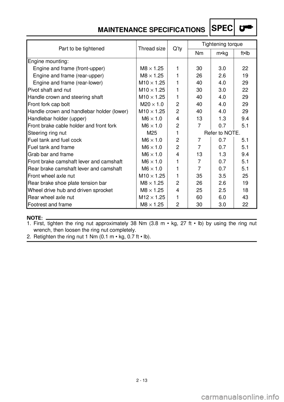
HINWEIS:NOTE:
1. First, tighten the ring nut approximately 38 Nm (3.8 m • kg, 27 ft • lb) by using the ring nut
wrench, then loosen the ring nut completely.
2. Retighten the ring nut 1 Nm (0.1 m • kg, 0.7 ft • lb).Part to be tightened Thread size Q’tyTightening torque
Nm m•kg ft•lb
Engine mounting:
Engine and frame (front-upper) M8 ´ 1.25 1 30 3.0 22
Engine and frame (rear-upper) M8 ´ 1.25 1 26 2.6 19
Engine and frame (rear-lower) M10 ´ 1.25 1 40 4.0 29
Pivot shaft and nut M10 ´ 1.25 1 30 3.0 22
Handle crown and steering shaft M10 ´ 1.25 1 40 4.0 29
Front fork cap bolt M20 ´ 1.0 2 40 4.0 29
Handle crown and handlebar holder (lower) M10 ´ 1.25 2 40 4.0 29
Handlebar holder (upper) M6 ´ 1.0 4 13 1.3 9.4
Front brake cable holder and front fork M6 ´ 1.0 2 7 0.7 5.1
Steering ring nut M25 1 Refer to NOTE.
Fuel tank and fuel cock M6 ´ 1.0 2 7 0.7 5.1
Fuel tank and frame M6 ´ 1.0 2 7 0.7 5.1
Grab bar and frame M6 ´ 1.0 4 13 1.3 9.4
Front brake camshaft lever and camshaft M6 ´ 1.0 1 7 0.7 5.1
Rear brake camshaft lever and camshaft M6 ´ 1.0 1 7 0.7 5.1
Front wheel axle nut M10 ´ 1.25 1 35 3.5 25
Rear brake shoe plate tension bar M8 ´ 1.25 2 26 2.6 19
Wheel drive hub and driven sprocket M8 ´ 1.25 4 25 2.5 18
Rear wheel axle nut M12 ´ 1.25 1 60 6.0 43
Footrest and frame M8 ´ 1.25 2 30 3.0 22
MAINTENANCE SPECIFICATIONS
Page 108 of 287
3 - 1
INSP
ADJ
MAINTENANCE INTERVALS/
PERIODIC MAINTENANCE AND LUBRICATION
EC300000
REGULAR INSPECTION AND ADJUSTMENTS
EC310022
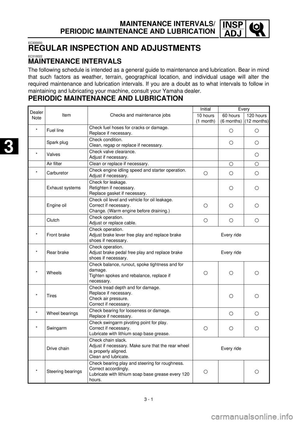
MAINTENANCE INTERVALS
The following schedule is intended as a general guide to maintenance and lubrication. Bear in mind
that such factors as weather, terrain, geographical location, and individual usage will alter the
required maintenance and lubrication intervals. If you are a doubt as to what intervals to follow in
maintaining and lubricating your machine, consult your Yamaha dealer.
PERIODIC MAINTENANCE AND LUBRICATION
Dealer
NoteItem Checks and maintenance jobsInitial Every
10 hours
(1 month)60 hours
(6 months)120 hours
(12 months)
* Fuel lineCheck fuel hoses for cracks or damage.
Replace if necessary.
Spark plugCheck condition.
Clean, regap or replace if necessary.
* ValvesCheck valve clearance.
Adjust if necessary.
Air filter Clean or replace if necessary.
* CarburetorCheck engine idling speed and starter operation.
Adjust if necessary.
Exhaust systemsCheck for leakage.
Retighten if necessary.
Replace gasket if necessary.
Engine oilCheck oil level and vehicle for oil leakage.
Correct if necessary.
Change. (Warm engine before draining.)
ClutchCheck operation.
Adjust or replace cable.
* Front brakeCheck operation.
Adjust brake lever free play and replace brake
shoes if necessary.Every ride
* Rear brakeCheck operation.
Adjust brake pedal free play and replace brake
shoes if necessary.Every ride
* WheelsCheck balance, runout, spoke tightness and for
damage.
Tighten spokes and rebalance, replace if
necessary.
* TiresCheck tread depth and for damage.
Replace if necessary.
Check air pressure.
Correct if necessary.
* Wheel bearingsCheck bearing for looseness or damage.
Replace if necessary.
* SwingarmCheck swingarm pivoting point for play.
Correct if necessary.
Lubricate with lithium soap base grease.
Drive chainCheck chain slack.
Adjust if necessary. Make sure that the rear wheel
is properly aligned.
Clean and lubricate.Every ride
* Steering bearingsCheck bearing play and steering for roughness.
Correct accordingly.
Lubricate with lithium soap base grease every 120
hours.
3
3
Page 109 of 287
3 - 2
INSP
ADJ
PRE-OPERATION INSPECTION AND MAINTENANCE
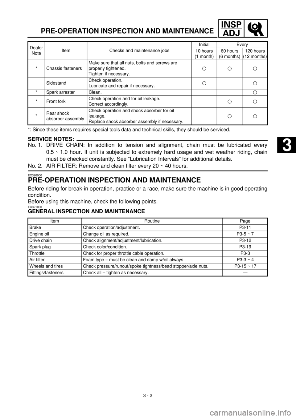
*: Since these items requires special tools data and technical skills, they should be serviced.
SERVICE NOTES:
No. 1. DRIVE CHAIN: In addition to tension and alignment, chain must be lubricated every
0.5 ~ 1.0 hour. If unit is subjected to extremely hard usage and wet weather riding, chain
must be checked constantly. See “Lubrication Intervals” for additional details.
No. 2. AIR FILTER: Remove and clean filter every 20 ~ 40 hours.
EC320000
PRE-OPERATION INSPECTION AND MAINTENANCE
Before riding for break-in operation, practice or a race, make sure the machine is in good operating
condition.
Before using this machine, check the following points.
EC321000
GENERAL INSPECTION AND MAINTENANCE
* Chassis fastenersMake sure that all nuts, bolts and screws are
properly tightened.
Tighten if necessary.
SidestandCheck operation.
Lubricate and repair if necessary.
* Spark arrester Clean.
* Front forkCheck operation and for oil leakage.
Correct accordingly.
*Rear shock
absorber assemblyCheck operation and shock absorber for oil
leakage.
Replace shock absorber assembly if necessary.
Item Routine Page
Brake Check operation/adjustment. P3-11
Engine oil Change oil as required. P3-5 ~ 7
Drive chain Check alignment/adjustment/lubrication. P3-12
Spark plug Check color/condition. P3-19
Throttle Check for proper throttle cable operation. P3-3
Air filter Foam type – must be clean and damp w/oil always P3-3 ~ 4
Wheels and tires Check pressure/runout/spoke tightness/bead stopper/axle nuts. P3-15 ~ 17
Fittings/fasteners Check all – tighten as necessary. —Dealer
NoteItem Checks and maintenance jobsInitial Every
10 hours
(1 month)60 hours
(6 months)120 hours
(12 months)
3
Page 132 of 287
3 - 12
INSP
ADJ
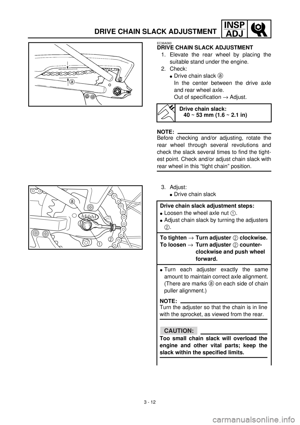
DRIVE CHAIN SLACK ADJUSTMENT
EC36A060
DRIVE CHAIN SLACK ADJUSTMENT
1. Elevate the rear wheel by placing the
suitable stand under the engine.
2. Check:
lDrive chain slack a
In the center between the drive axle
and rear wheel axle.
Out of specification ® Adjust.
NOTE:
Before checking and/or adjusting, rotate the
rear wheel through several revolutions and
check the slack several times to find the tight-
est point. Check and/or adjust chain slack with
rear wheel in this “tight chain” position.
Drive chain slack:
40 ~ 53 mm (1.6 ~ 2.1 in)
3. Adjust:
lDrive chain slack
Drive chain slack adjustment steps:
lLoosen the wheel axle nut 1.
lAdjust chain slack by turning the adjusters
2.
To tighten ®Turn adjuster 2 clockwise.
To loosen ®Turn adjuster 2 counter-
clockwise and push wheel
forward.
lTurn each adjuster exactly the same
amount to maintain correct axle alignment.
(There are marks a on each side of chain
puller alignment.)
12 a
NOTE:
Turn the adjuster so that the chain is in line
with the sprocket, as viewed from the rear.
CAUTION:
Too small chain slack will overload the
engine and other vital parts; keep the
slack within the specified limits.
Page 134 of 287
3 - 13
INSP
ADJFRONT FORK INSPECTION/REAR SHOCK ABSORBER INSPECTION/
REAR SHOCK ABSORBER SPRING PRELOAD ADJUSTMENT
lTighten the wheel axle nut while pushing
down the drive chain.
T R..
Axle nut:
60 Nm (6.0 m • kg, 43 ft • lb)
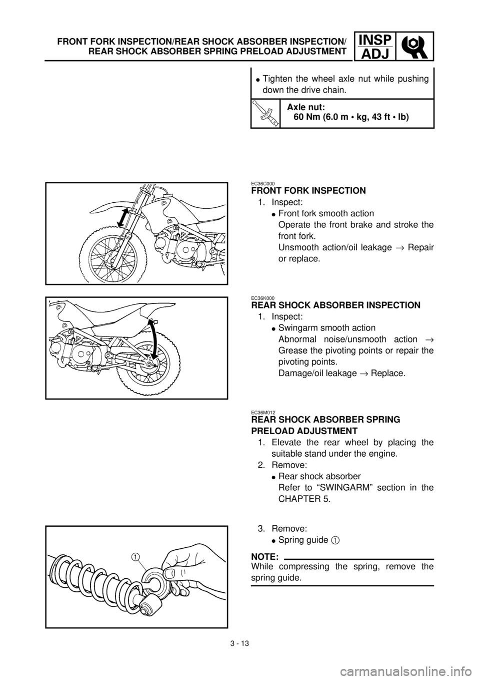
EC36C000
FRONT FORK INSPECTION
1. Inspect:
lFront fork smooth action
Operate the front brake and stroke the
front fork.
Unsmooth action/oil leakage ® Repair
or replace.
EC36K000
REAR SHOCK ABSORBER INSPECTION
1. Inspect:
lSwingarm smooth action
Abnormal noise/unsmooth action ®
Grease the pivoting points or repair the
pivoting points.
Damage/oil leakage ® Replace.
EC36M012
REAR SHOCK ABSORBER SPRING
PRELOAD ADJUSTMENT
1. Elevate the rear wheel by placing the
suitable stand under the engine.
2. Remove:
lRear shock absorber
Refer to “SWINGARM” section in the
CHAPTER 5.
3. Remove:
lSpring guide 1
NOTE:
While compressing the spring, remove the
spring guide.