brake YAMAHA TTR90 2000 Owners Manual
[x] Cancel search | Manufacturer: YAMAHA, Model Year: 2000, Model line: TTR90, Model: YAMAHA TTR90 2000Pages: 287, PDF Size: 6.77 MB
Page 26 of 287
1 - 1
GEN
INFO
DESCRIPTION
EC100000
GENERAL INFORMATION
EC110000
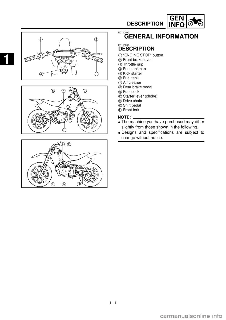
DESCRIPTION
1
“ENGINE STOP” button
2
Front brake lever
3
Throttle grip
4
Fuel tank cap
5
Kick starter
6
Fuel tank
7
Air cleaner
8
Rear brake pedal
9
Fuel cock
0
Starter lever (choke)
A
Drive chain
B
Shift pedal
C
Front fork
NOTE:
l
The machine you have purchased may differ
slightly from those shown in the following.
l
Designs and specifications are subject to
change without notice.
1
1
Page 46 of 287
1 - 9
GEN
INFO
CONTROL FUNCTIONS
EC150000
CONTROL FUNCTIONS
EC151000
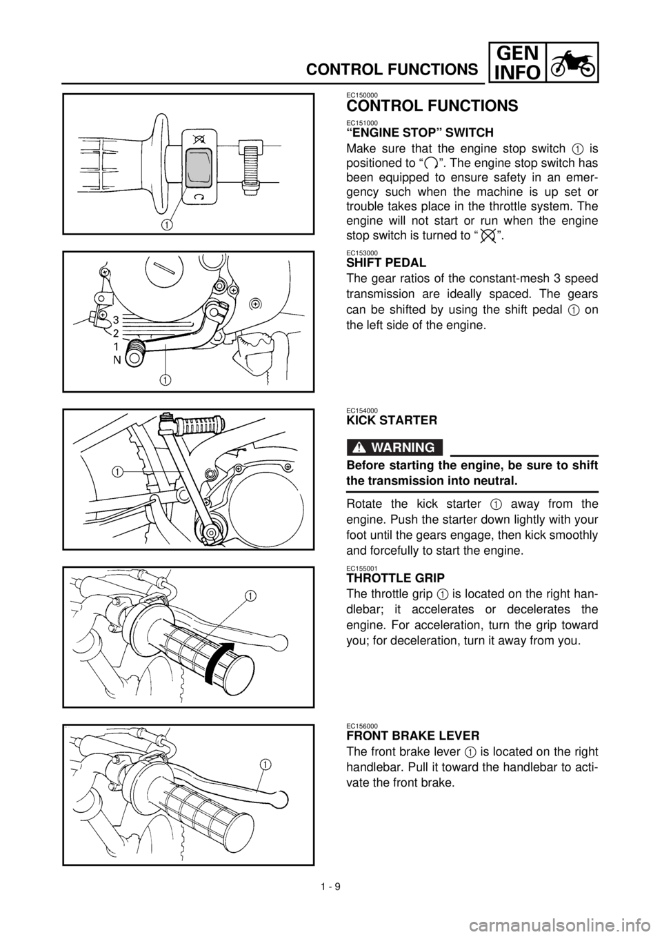
“ENGINE STOP” SWITCH
Make sure that the engine stop switch 1 is
positioned to “ ”. The engine stop switch has
been equipped to ensure safety in an emer-
gency such when the machine is up set or
trouble takes place in the throttle system. The
engine will not start or run when the engine
stop switch is turned to “ ”.
EC153000
SHIFT PEDAL
The gear ratios of the constant-mesh 3 speed
transmission are ideally spaced. The gears
can be shifted by using the shift pedal 1 on
the left side of the engine.
EC154000
KICK STARTER
WARNING
Before starting the engine, be sure to shift
the transmission into neutral.
Rotate the kick starter 1 away from the
engine. Push the starter down lightly with your
foot until the gears engage, then kick smoothly
and forcefully to start the engine.
EC155001
THROTTLE GRIP
The throttle grip 1 is located on the right han-
dlebar; it accelerates or decelerates the
engine. For acceleration, turn the grip toward
you; for deceleration, turn it away from you.
EC156000
FRONT BRAKE LEVER
The front brake lever 1 is located on the right
handlebar. Pull it toward the handlebar to acti-
vate the front brake.
Page 48 of 287
1 - 10
GEN
INFO
CONTROL FUNCTIONS
EC157000
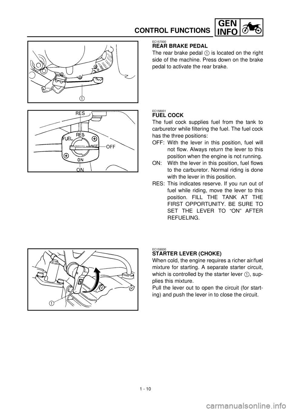
REAR BRAKE PEDAL
The rear brake pedal 1 is located on the right
side of the machine. Press down on the brake
pedal to activate the rear brake.
EC158001
FUEL COCK
The fuel cock supplies fuel from the tank to
carburetor while filtering the fuel. The fuel cock
has the three positions:
OFF: With the lever in this position, fuel will
not flow. Always return the lever to this
position when the engine is not running.
ON: With the lever in this position, fuel flows
to the carburetor. Normal riding is done
with the lever in this position.
RES: This indicates reserve. If you run out of
fuel while riding, move the lever to this
position. FILL THE TANK AT THE
FIRST OPPORTUNITY. BE SURE TO
SET THE LEVER TO “ON” AFTER
REFUELING.
EC159000
STARTER LEVER (CHOKE)
When cold, the engine requires a richer air/fuel
mixture for starting. A separate starter circuit,
which is controlled by the starter lever 1, sup-
plies this mixture.
Pull the lever out to open the circuit (for start-
ing) and push the lever in to close the circuit.
Page 57 of 287
SPEC
2 - 2
Fuel:
Type Unleaded fuel (USA)
Premium unleaded gasoline (CDN, Europe)
Unleaded fuel only (AUS)
Premium gasoline (Oceania)
Tank capacity 4.1 L (0.90 lmp gal, 1.08 US gal)
Reserve amount 0.5 L (0.11 Imp gal, 0.13 US gal)
Carburetor:
Type VM16SH
Manufacturer MIKUNI
Spark plug:
Type CR6HSA/U20FSR-U
Manufacturer NGK/DENSO
Gap 0.6 ~ 0.7 mm (0.02 ~ 0.03 in)
Clutch type: Wet, multiple-disc and centrifugal automatic
Transmission:
Primary reduction system Spur gear
Primary reduction ratio 67/18 (3.722)
Secondary reduction system Chain drive
Secondary reduction ratio 35/14 (2.500)
Transmission type Constant mesh, 3-speed
Operation Left foot operation
Gear ratio: 1st 37/13 (2.846)
2nd 33/19 (1.736)
3rd 28/23 (1.217)
Chassis:
Frame type Double cradle
Caster angle 24.83˚
Trail 56.0 mm (2.2 in)
Tire:
Type With tube
Size (front) 2.50-14 4PR
Size (rear) 3.00-12 4PR
Manufacturer (front and rear) CHENG SHIN
Type (front and rear) KNOBBY
Tire pressure (front and rear) 100 kPa (1.00 kg/cm
2
, 14.5 psi)
Brake:
Front brake type Drum brake
Operation Right hand operation
Rear brake type Drum brake
Operation Right foot operation
Suspension:
Front suspension Telescopic fork
Rear suspension Swingarm (monocross suspension)
GENERAL SPECIFICATIONS
2
Page 67 of 287

SPEC
2 - 12
Drum brake:
Front drum brake type Leading, trailing ----
Rear drum brake type Leading, trailing ----
Front drum inside diameter 95 mm (3.74 in) 96 mm (3.78 in)
Rear drum inside diameter 110 mm (4.33 in) 111 mm (4.37 in)
Front lining thickness 3 mm (0.12 in) 1.5 mm (0.06 in)
Rear lining thickness 4 mm (0.16 in) 1.5 mm (0.06 in)
Front shoe spring free length 32.7 mm (1.29 in) ----
Rear shoe spring free length 50.5 mm (1.99 in) ----
Brake lever and brake pedal:
Brake lever free play (lever end) 10 ~ 20 mm (0.39 ~ 0.79 in) ----
Brake pedal position
(vertical height below footrest top)15 mm (0.59 in) ----
Brake pedal free play 10 ~ 20 mm (0.39 ~ 0.79 in) ----
Throttle grip free play 3 ~ 5 mm (0.12 ~ 0.20 in) ----Item Standard Limit
MAINTENANCE SPECIFICATIONS
Page 68 of 287
SPEC
2 - 13
HINWEIS:NOTE:
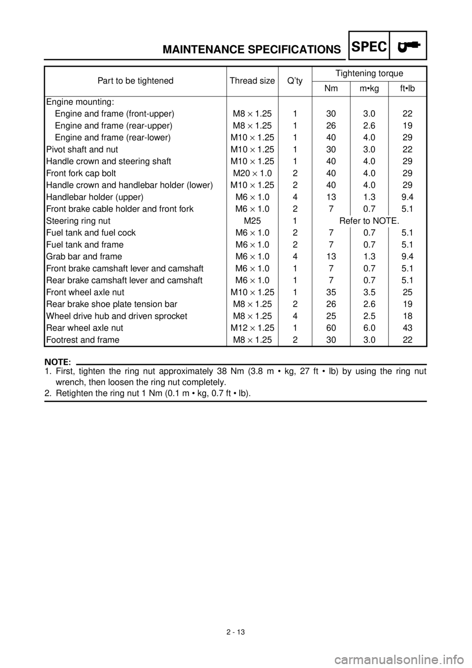
1. First, tighten the ring nut approximately 38 Nm (3.8 m • kg, 27 ft • lb) by using the ring nut
wrench, then loosen the ring nut completely.
2. Retighten the ring nut 1 Nm (0.1 m • kg, 0.7 ft • lb).Part to be tightened Thread size Q’tyTightening torque
Nm m•kg ft•lb
Engine mounting:
Engine and frame (front-upper) M8 ´ 1.25 1 30 3.0 22
Engine and frame (rear-upper) M8 ´ 1.25 1 26 2.6 19
Engine and frame (rear-lower) M10 ´ 1.25 1 40 4.0 29
Pivot shaft and nut M10 ´ 1.25 1 30 3.0 22
Handle crown and steering shaft M10 ´ 1.25 1 40 4.0 29
Front fork cap bolt M20 ´ 1.0 2 40 4.0 29
Handle crown and handlebar holder (lower) M10 ´ 1.25 2 40 4.0 29
Handlebar holder (upper) M6 ´ 1.0 4 13 1.3 9.4
Front brake cable holder and front fork M6 ´ 1.0 2 7 0.7 5.1
Steering ring nut M25 1 Refer to NOTE.
Fuel tank and fuel cock M6 ´ 1.0 2 7 0.7 5.1
Fuel tank and frame M6 ´ 1.0 2 7 0.7 5.1
Grab bar and frame M6 ´ 1.0 4 13 1.3 9.4
Front brake camshaft lever and camshaft M6 ´ 1.0 1 7 0.7 5.1
Rear brake camshaft lever and camshaft M6 ´ 1.0 1 7 0.7 5.1
Front wheel axle nut M10 ´ 1.25 1 35 3.5 25
Rear brake shoe plate tension bar M8 ´ 1.25 2 26 2.6 19
Wheel drive hub and driven sprocket M8 ´ 1.25 4 25 2.5 18
Rear wheel axle nut M12 ´ 1.25 1 60 6.0 43
Footrest and frame M8 ´ 1.25 2 30 3.0 22
MAINTENANCE SPECIFICATIONS
Page 102 of 287
2 - 16
SPEC
CABLE ROUTING DIAGRAM
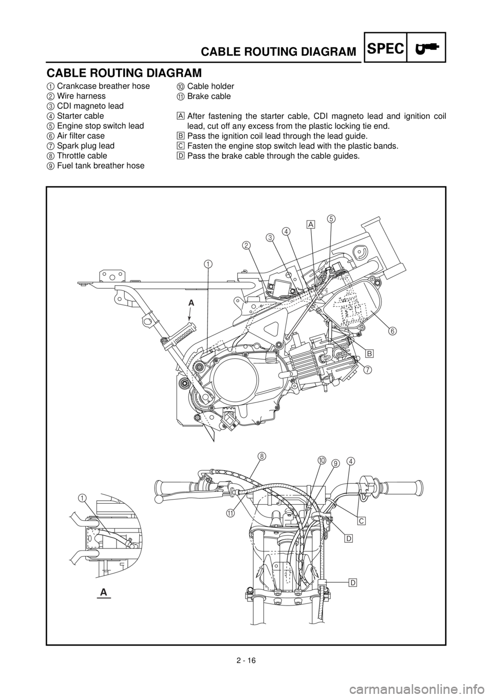
CABLE ROUTING DIAGRAM
1
Crankcase breather hose
2
Wire harness
3
CDI magneto lead
4
Starter cable
5
Engine stop switch lead
6
Air filter case
7
Spark plug lead
8
Throttle cable
9
Fuel tank breather hose
0
Cable holder
A
Brake cable
After fastening the starter cable, CDI magneto lead and ignition coil
lead, cut off any excess from the plastic locking tie end.
õ
Pass the ignition coil lead through the lead guide.
‚
Fasten the engine stop switch lead with the plastic bands.
ë
Pass the brake cable through the cable guides.
12345
6
7
8
9 0
4
A 1
õ
‚
ë
ë
A
A
Page 104 of 287
2 - 17
SPEC
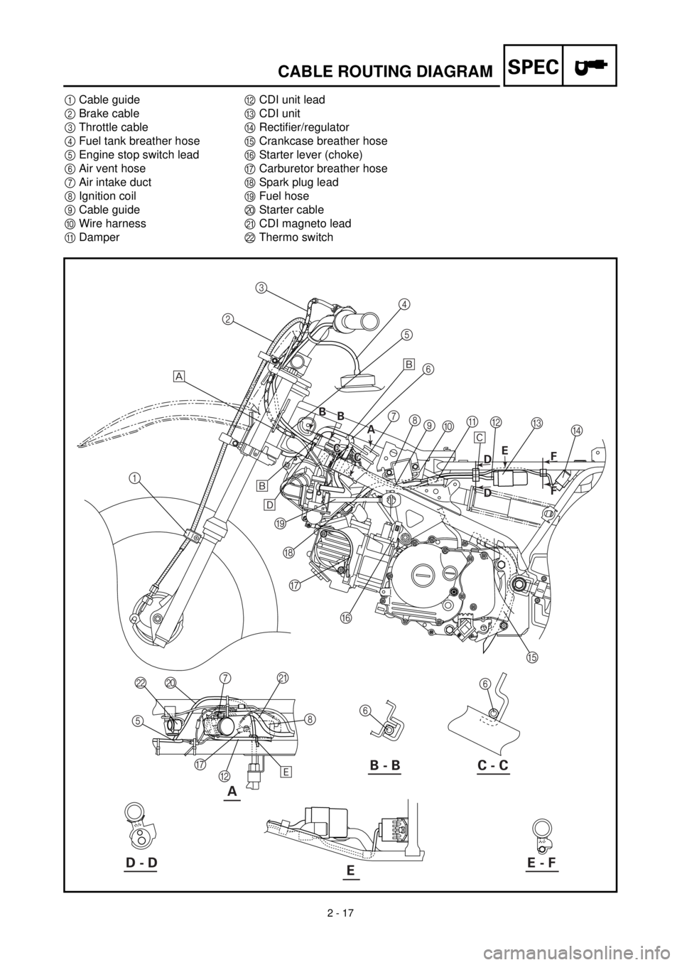
CABLE ROUTING DIAGRAM
1
Cable guide
2
Brake cable
3
Throttle cable
4
Fuel tank breather hose
5
Engine stop switch lead
6
Air vent hose
7
Air intake duct
8
Ignition coil
9
Cable guide
0
Wire harness
A
Damper
B
CDI unit lead
C
CDI unit
D
Rectifier/regulator
E
Crankcase breather hose
F
Starter lever (choke)
G
Carburetor breather hose
H
Spark plug lead
I
Fuel hose
J
Starter cable
K
CDI magneto lead
L
Thermo switch
A
123
4
5
6
7
8
9
0A
C
D B
E F G H I
6
6 J L
5
G
B8 K
7 õ
‚
õ
ë
ä
B - B C - C
D - DE - FE
A A B
B B
B
C
C C
CE
B D
B D
F
F F F
Page 108 of 287
3 - 1
INSP
ADJ
MAINTENANCE INTERVALS/
PERIODIC MAINTENANCE AND LUBRICATION
EC300000
REGULAR INSPECTION AND ADJUSTMENTS
EC310022
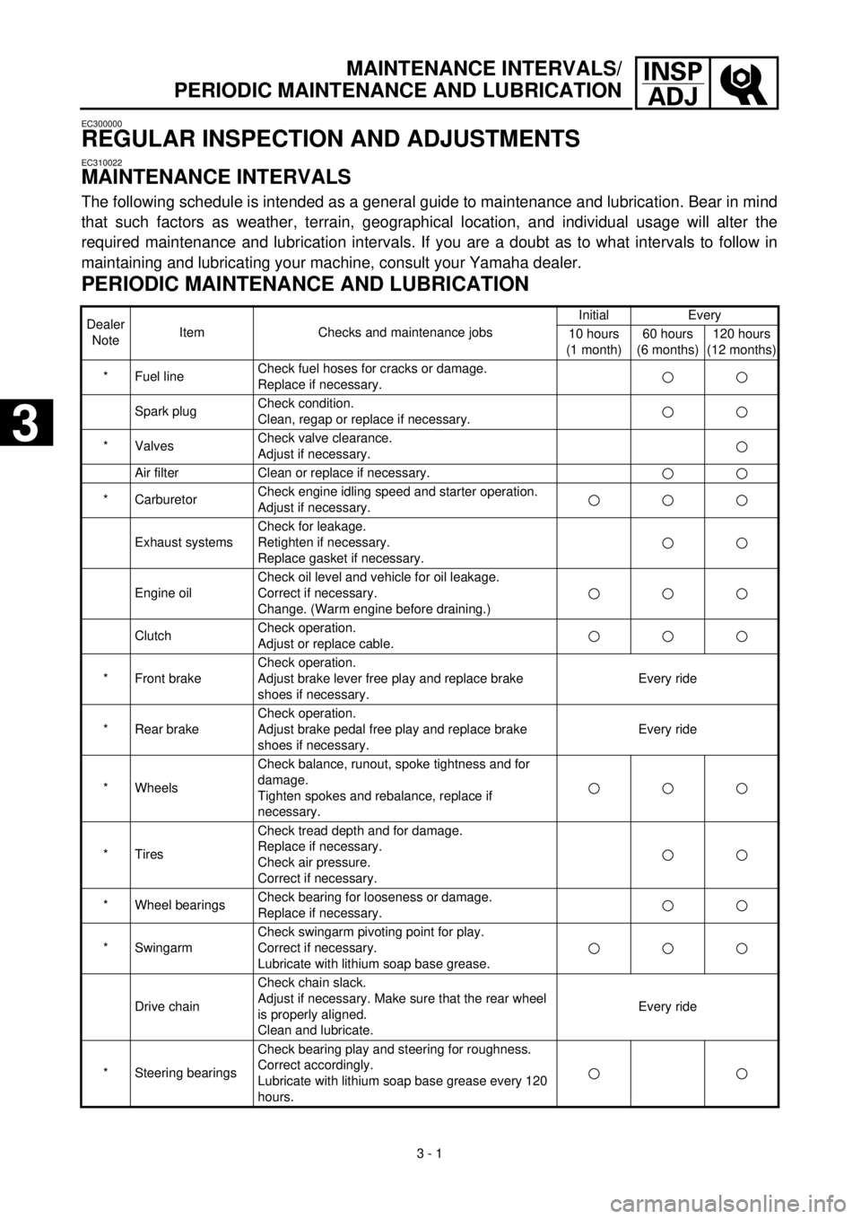
MAINTENANCE INTERVALS
The following schedule is intended as a general guide to maintenance and lubrication. Bear in mind
that such factors as weather, terrain, geographical location, and individual usage will alter the
required maintenance and lubrication intervals. If you are a doubt as to what intervals to follow in
maintaining and lubricating your machine, consult your Yamaha dealer.
PERIODIC MAINTENANCE AND LUBRICATION
Dealer
NoteItem Checks and maintenance jobsInitial Every
10 hours
(1 month)60 hours
(6 months)120 hours
(12 months)
* Fuel lineCheck fuel hoses for cracks or damage.
Replace if necessary.
Spark plugCheck condition.
Clean, regap or replace if necessary.
* ValvesCheck valve clearance.
Adjust if necessary.
Air filter Clean or replace if necessary.
* CarburetorCheck engine idling speed and starter operation.
Adjust if necessary.
Exhaust systemsCheck for leakage.
Retighten if necessary.
Replace gasket if necessary.
Engine oilCheck oil level and vehicle for oil leakage.
Correct if necessary.
Change. (Warm engine before draining.)
ClutchCheck operation.
Adjust or replace cable.
* Front brakeCheck operation.
Adjust brake lever free play and replace brake
shoes if necessary.Every ride
* Rear brakeCheck operation.
Adjust brake pedal free play and replace brake
shoes if necessary.Every ride
* WheelsCheck balance, runout, spoke tightness and for
damage.
Tighten spokes and rebalance, replace if
necessary.
* TiresCheck tread depth and for damage.
Replace if necessary.
Check air pressure.
Correct if necessary.
* Wheel bearingsCheck bearing for looseness or damage.
Replace if necessary.
* SwingarmCheck swingarm pivoting point for play.
Correct if necessary.
Lubricate with lithium soap base grease.
Drive chainCheck chain slack.
Adjust if necessary. Make sure that the rear wheel
is properly aligned.
Clean and lubricate.Every ride
* Steering bearingsCheck bearing play and steering for roughness.
Correct accordingly.
Lubricate with lithium soap base grease every 120
hours.
3
3
Page 109 of 287
3 - 2
INSP
ADJ
PRE-OPERATION INSPECTION AND MAINTENANCE
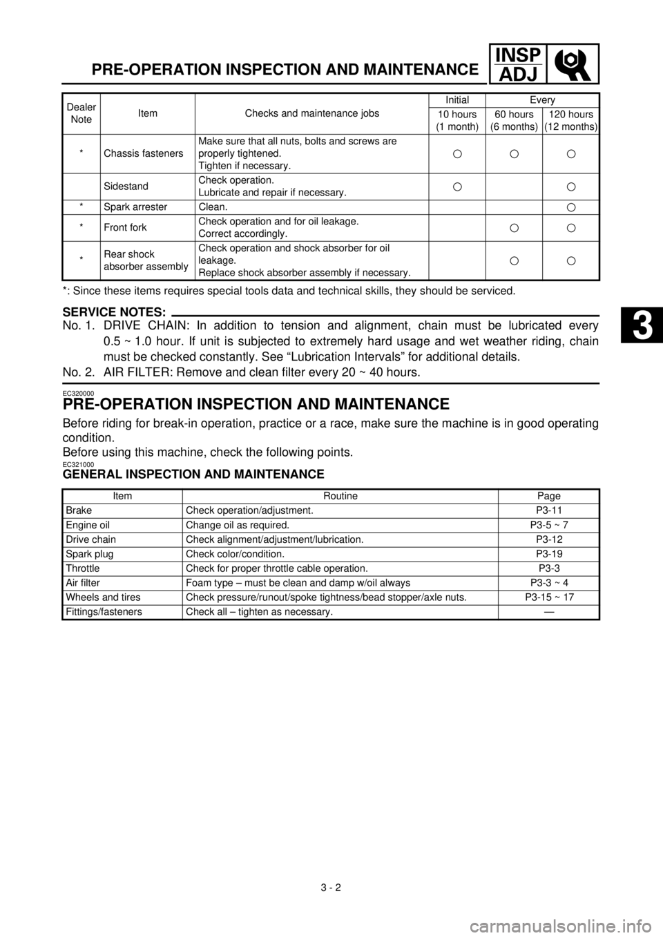
*: Since these items requires special tools data and technical skills, they should be serviced.
SERVICE NOTES:
No. 1. DRIVE CHAIN: In addition to tension and alignment, chain must be lubricated every
0.5 ~ 1.0 hour. If unit is subjected to extremely hard usage and wet weather riding, chain
must be checked constantly. See “Lubrication Intervals” for additional details.
No. 2. AIR FILTER: Remove and clean filter every 20 ~ 40 hours.
EC320000
PRE-OPERATION INSPECTION AND MAINTENANCE
Before riding for break-in operation, practice or a race, make sure the machine is in good operating
condition.
Before using this machine, check the following points.
EC321000
GENERAL INSPECTION AND MAINTENANCE
* Chassis fastenersMake sure that all nuts, bolts and screws are
properly tightened.
Tighten if necessary.
SidestandCheck operation.
Lubricate and repair if necessary.
* Spark arrester Clean.
* Front forkCheck operation and for oil leakage.
Correct accordingly.
*Rear shock
absorber assemblyCheck operation and shock absorber for oil
leakage.
Replace shock absorber assembly if necessary.
Item Routine Page
Brake Check operation/adjustment. P3-11
Engine oil Change oil as required. P3-5 ~ 7
Drive chain Check alignment/adjustment/lubrication. P3-12
Spark plug Check color/condition. P3-19
Throttle Check for proper throttle cable operation. P3-3
Air filter Foam type – must be clean and damp w/oil always P3-3 ~ 4
Wheels and tires Check pressure/runout/spoke tightness/bead stopper/axle nuts. P3-15 ~ 17
Fittings/fasteners Check all – tighten as necessary. —Dealer
NoteItem Checks and maintenance jobsInitial Every
10 hours
(1 month)60 hours
(6 months)120 hours
(12 months)
3