drain bolt YAMAHA TTR90 2000 Owners Manual
[x] Cancel search | Manufacturer: YAMAHA, Model Year: 2000, Model line: TTR90, Model: YAMAHA TTR90 2000Pages: 287, PDF Size: 6.77 MB
Page 65 of 287

SPEC
2 - 10
Part to be tightened Thread size Q’tyTightening torque
Nm m•kg ft•lb
Cylinder head nut M8
´
1.25 4 22 2.2 16
Cylinder head bolt M6
´
1.0 2 10 1.0 7.2
Spark plug M10
´
1.0 1 13 1.3 9.4
Cylinder head side cover bolt M6
´
1.0 2 7 0.7 5.1
Tappet cover M45
´
1.5 2 18 1.8 13
Exhaust pipe stud bolt M6
´
1.0 2 7 0.7 5.1
Magneto rotor nut M12
´
1.25 1 48 4.8 35
Timing chain guide (rear) M6
´
1.0 2 10 1.0 7.2
Valve clearance adjust screw locknut M5
´
0.5 2 7 0.7 5.1
Camshaft sprocket M8
´
1.25 1 20 2.0 14
Camshaft bearing retainer M6
´
1.0 1 10 1.0 7.2
Timing chain tensioner cap bolt M8
´
1.25 1 8 0.8 5.8
Timing chain tensioner M6
´
1.0 2 10 1.0 7.2
Oil pump M6
´
1.0 2 7 0.7 5.1
Drain plug M12
´
1.5 1 20 2.0 14
Carburetor joint (cylinder head side) M6
´
1.0 2 7 0.7 5.1
Carburetor joint (carburetor side) M6
´
1.0 2 7 0.7 5.1
Air filter case M6
´
1.0 2 7 0.7 5.1
Exhaust pipe M6
´
1.0 2 7 0.7 5.1
Exhaust pipe M5
´
0.8 2 4 0.4 2.9
Exhaust pipe protector M6
´
1.0 5 7 0.7 5.1
Silencer M8
´
1.25 1 24 2.4 17
Crankcase M6
´
1.0 9 10 1.0 7.2
Crankcase cover (left) M6
´
1.0 8 7 0.7 5.1
Drive sprocket cover M6
´
1.0 2 7 0.7 5.1
Crankcase cover (right) M6
´
1.0 9 7 0.7 5.1
Timing plug M14
´
1.5 1 7 0.7 5.1
Crankshaft end cover M32
´
1.5 1 7 0.7 5.1
Cylinder head stud bolt M8
´
1.25 4 13 1.3 9.4
Kick crank M6
´
1.0 1 10 1.0 7.2
Primary drive gear M12
´
1.0 1 50 5.0 36
Pressure plate M5
´
0.8 4 6 0.6 4.3
Clutch boss M14
´
1.0 1 60 6.0 43
Main axle bearing retainer M6
´
1.0 1 10 1.0 7.2
Shift pedal M6
´
1.0 1 8 0.8 5.8
Clutch adjust screw locknut M6
´
1.0 1 8 0.8 5.8
Pickup coil M6
´
1.0 2 10 1.0 7.2
Stator assembly M6
´
1.0 3 10 1.0 7.2
MAINTENANCE SPECIFICATIONS
Page 120 of 287

3 - 6
INSP
ADJ
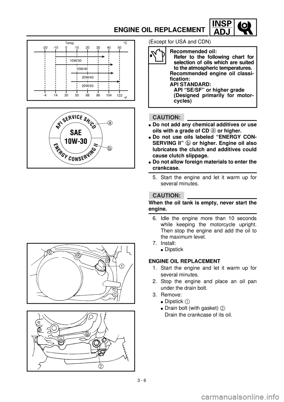
ENGINE OIL REPLACEMENT
(Except for USA and CDN)
CAUTION:
l
Do not add any chemical additives or use
oils with a grade of CD
a or higher.
lDo not use oils labeled “ENERGY CON-
SERVING II” b or higher. Engine oil also
lubricates the clutch and additives could
cause clutch slippage.
lDo not allow foreign materials to enter the
crankcase.
5. Start the engine and let it warm up for
several minutes.
CAUTION:
When the oil tank is empty, never start the
engine.
6. Idle the engine more than 10 seconds
while keeping the motorcycle upright.
Then stop the engine and add the oil to
the maximum level.
7. Install:
lDipstick
ENGINE OIL REPLACEMENT
1. Start the engine and let it warm up for
several minutes.
2. Stop the engine and place an oil pan
under the drain bolt.
3. Remove:
lDipstick 1
lDrain bolt (with gasket) 2
Drain the crankcase of its oil.
Recommended oil:
Refer to the following chart for
selection of oils which are suited
to the atmospheric temperatures.
Recommended engine oil classi-
fication:
API STANDARD:
API “SE/SF” or higher grade
(Designed primarily for motor-
cycles)-20
-4-10
140
3010
5020
6830
8640 50
104
122¡CTemp.
¡F
10W/30
10W/40
20W/40
20W/50
a
b
Page 122 of 287

3 - 7
INSP
ADJ
PILOT AIR SCREW ADJUSTMENT
4. Install:
lGasket
lDrain bolt
New
T R..20 Nm (2.0 m · kg, 14 ft · lb)
5. Fill:
lCrankcase
Oil quantity:
Total amount:
1.0 L (0.88 Imp qt, 1.06 US qt)
Periodic oil change:
0.8 L (0.70 Imp qt, 0.85 US qt)
6. Install:
lDipstick
7. Inspect:
lEngine (for oil leaks)
lOil level
Refer to “ENGINE OIL LEVEL INSPEC-
TION”.
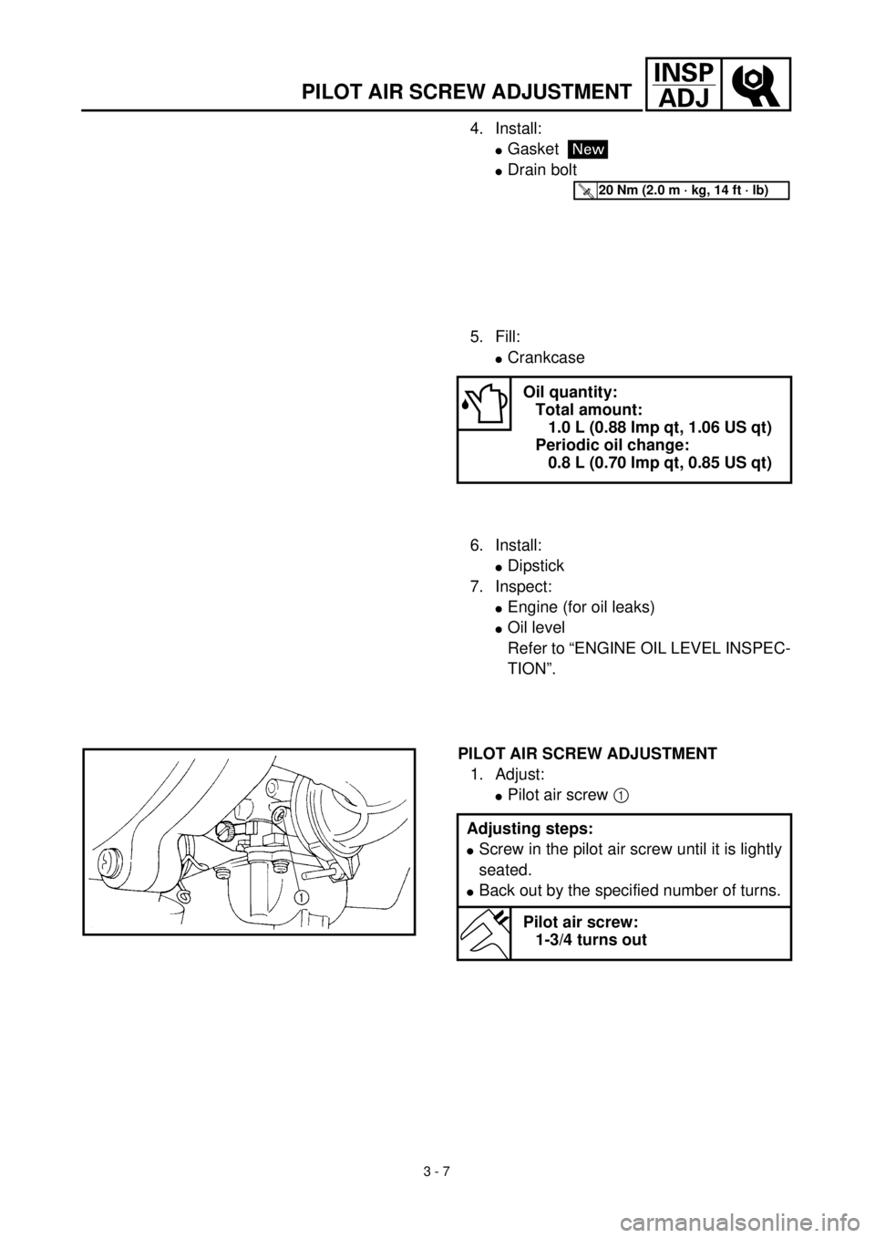
PILOT AIR SCREW ADJUSTMENT
1. Adjust:
lPilot air screw 1
Adjusting steps:
lScrew in the pilot air screw until it is lightly
seated.
lBack out by the specified number of turns.
Pilot air screw:
1-3/4 turns out
Page 252 of 287

5 - 7
CHAS
FRONT FORK
EC558000
FRONT FORK DISASSEMBLY
Extent of removal:
1
Oil seal removal
2
Damper rod removal
Extent of removal Order Part name Q’ty Remarks
FRONT FORK DISASSEMBLY
Preparation for disas-
semblyDrain the fork oil.
1
Adjuster 1
2
Fork spring 1
3
Dust cover 1
4
Stopper ring 1
5
Bolt (damper rod) 1
Use special tool.
Refer to “REMOVAL POINTS”.
6
Inner tube 1
7
Damper rod 1
8
Oil seal 1
9
Outer tube 1
12