engine oil YAMAHA TTR90 2000 Owners Manual
[x] Cancel search | Manufacturer: YAMAHA, Model Year: 2000, Model line: TTR90, Model: YAMAHA TTR90 2000Pages: 287, PDF Size: 6.77 MB
Page 18 of 287
EC085001
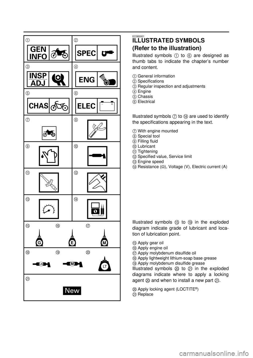
ILLUSTRATED SYMBOLS
(Refer to the illustration)
Illustrated symbols
1
to
6
are designed as
thumb tabs to indicate the chapter’s number
and content.
1
General information
2
Specifications
3
Regular inspection and adjustments
4
Engine
5
Chassis
6
Electrical
Illustrated symbols
7
to
D
are used to identify
the specifications appearing in the text.
7
With engine mounted
8
Special tool
9
Filling fluid
0
Lubricant
A
Tightening
B
Specified value, Service limit
C
Engine speed
DResistance (W), Voltage (V), Electric current (A)
Illustrated symbols E to I in the exploded
diagram indicate grade of lubricant and loca-
tion of lubrication point.
EApply gear oil
FApply engine oil
GApply molybdenum disulfide oil
HApply lightweight lithium-soap base grease
IApply molybdenum disulfide grease
Illustrated symbols J to K in the exploded
diagrams indicate where to apply a locking
agent J and when to install a new part K.
JApply locking agent (LOCTITE®)
KReplace 12
34
56
78
90
AB
CD
EFG
HIJ
K
GEN
INFOSPEC
INSP
ADJENG
CHAS–+ELEC
T R..
GME
MLTLS
New
Page 24 of 287

CHAPTER 4
ENGINE
CARBURETOR
......................................... 4-1
CYLINDER HEAD
..................................... 4-8
CAMSHAFT AND ROCKER ARMS
....... 4-13
VALVES AND VALVE SPRINGS
........... 4-16
CYLINDER AND PISTON
....................... 4-21
CLUTCH
.................................................. 4-27
KICK AXLE
............................................. 4-33
SHIFT SHAFT
......................................... 4-34
OIL PUMP
............................................... 4-36
CDI MAGNETO
....................................... 4-39
CRANKCASE AND CRANKSHAFT
....... 4-41
SHIFT FORK, SHIFT CAM AND
TRANSMISSION
..................................... 4-44
CHAPTER 5
CHASSIS
FRONT WHEEL AND REAR WHEEL
...... 5-1
FRONT FORK
........................................... 5-6
HANDLEBAR
............................................ 5-9
STEERING
.............................................. 5-10
SWINGARM
............................................ 5-11
CHAPTER 6
ELECTRICAL
ELECTRICAL COMPONENTS AND
WIRING DIAGRAM
................................... 6-1
IGNITION SYSTEM
................................... 6-2
CARBURETOR HEATING SYSTEM
........ 6-6
MAINTENANCE RECORD
....................... 6-9
Page 32 of 287
1 - 4
GEN
INFO
IMPORTANT INFORMATION
EC133000
GASKETS, OIL SEALS AND O-RINGS
1. All gaskets, oil seals, and O-rings should
be replaced when an engine is over-
hauled. All gasket surfaces, oil seal lips,
and O-rings must be cleaned.
2. Properly oil all mating parts and bearings
during reassembly. Apply grease to the
oil seal lips.
EC134000
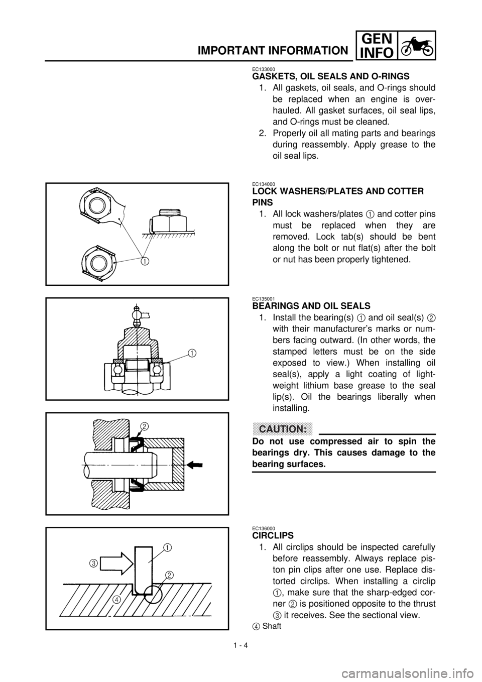
LOCK WASHERS/PLATES AND COTTER
PINS
1. All lock washers/plates
1
and cotter pins
must be replaced when they are
removed. Lock tab(s) should be bent
along the bolt or nut flat(s) after the bolt
or nut has been properly tightened.
EC135001
BEARINGS AND OIL SEALS
1. Install the bearing(s)
1
and oil seal(s)
2
with their manufacturer’s marks or num-
bers facing outward. (In other words, the
stamped letters must be on the side
exposed to view.) When installing oil
seal(s), apply a light coating of light-
weight lithium base grease to the seal
lip(s). Oil the bearings liberally when
installing.
CAUTION:
Do not use compressed air to spin the
bearings dry. This causes damage to the
bearing surfaces.
EC136000
CIRCLIPS
1. All circlips should be inspected carefully
before reassembly. Always replace pis-
ton pin clips after one use. Replace dis-
torted circlips. When installing a circlip
1
, make sure that the sharp-edged cor-
ner
2
is positioned opposite to the thrust
3
it receives. See the sectional view.
4
Shaft
Page 36 of 287
GEN
INFO
1 - 6
SPECIAL TOOLS
EC140001
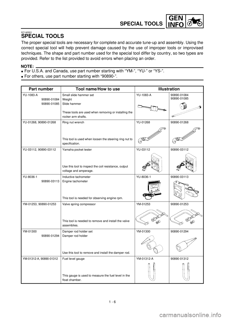
SPECIAL TOOLS
The proper special tools are necessary for complete and accurate tune-up and assembly. Using the
correct special tool will help prevent damage caused by the use of improper tools or improvised
techniques. The shape and part number used for the special tool differ by country, so two types are
provided. Refer to the list provided to avoid errors when placing an order.
NOTE:
l
For U.S.A. and Canada, use part number starting with “YM-”, “YU-” or “YS-”.
lFor others, use part number starting with “90890-”.
Part number Tool name/How to use Illustration
YU-1083-A
90890-01084
90890-01085Small slide hammer set
Weight
Slide hammer
These tools are used when removing or installing the
rocker arm shafts.YU-1083-A 90890-01084
90890-01085
YU-01268, 90890-01268 Ring nut wrench
This tool is used when loosen the steering ring nut to
specification.YU-01268 90890-01268
YU-03112, 90890-03112 Yamaha pocket tester
Use this tool to inspect the coil resistance, output
voltage and amperage.YU-03112 90890-03112
YU-8036-1
90890-03113Inductive tachometer
Engine tachometer
This tool is needed for observing engine rpm.YU-8036-1 90890-03113
YM-01253, 90890-01253 Valve spring compressor
This tool is needed to remove and install the valve
assemblies.YM-01253 90890-01253
YM-01300
90890-01294Damper rod holder set
Damper rod holder
Use this tool to remove and install the damper rod.YM-01300 90890-01294
YM-01312-A, 90890-01312Fuel level gauge
This gauge is used to measure the fuel level in the
float chamber.YM-01312-A 90890-01312
Page 52 of 287
GEN
INFO
1 - 12
STARTING AND OPERATION
STARTING AND OPERATION
CAUTION:
Prior to operating the machine, perform
steps listed in pre-operation check list.
WARNING
Never start your engine or let it run for any
length of time in a closed area. The exhaust
fumes are poisonous and can cause loss of
consciousness and death within a short
time. Always operate your machine in an
area with adequate ventilation.
STARTING A COLD ENGINE
WARNING
Before starting the engine, be sure to shift
the transmission into neutral.
1. Turn the fuel cock to “ON”.
2. Operate the starter (choke) and com-
pletely close the throttle grip.
3. Slide the “ENGINE STOP” switch to the
“”.
4. Kick the kick starter with full strength to
start the engine.
5. After the engine starts, warm up for one
or two minutes. Make sure the stater
(choke) is returned to the original position
before riding.
STARTING A WARM ENGINE
To start a warm engine, refer to the “Starting a
cold engine” section. The starter (choke)
should not be used. The throttle should be
opened slightly.
CAUTION:
See “Break-in Section” prior to operating
engine for the first time.WARMING UP
To get maximum engine life, always “warm-up”
the engine before starting off. Never acceler-
ate hard with a cold engine! To see whether or
not the engine is warm, see if it responds to
throttle normally with the stater (choke) turned
off.
WARNING
Before starting off, be sure to turn up or
remove the side stand.
Failure to retract the side stand completely
can result in a serious accident when you
try to turn a corner.
ENGINE BREAK-IN
1. Prior to starting, fill fuel tank with gasoline
and oil tank with specified oil.
2. Allow engine to warm up. Check engine
idling speed. Check operating controls
and engine stop switch operation.
3. Operate machine in lower gears at mod-
erate throttle setting for 3 ~ 5 minutes.
Check spark plug condition.
4. Allow engine to cool. Repeat procedure,
running for 5 minutes. Very briefly, shift to
higher gears and check full throttle
response. Check spark plug condition.
5. Allow engine to cool. Repeat procedure,
running for 5 minutes. Full throttle and
higher gears may be used, but avoid sus-
tained full throttle operation. Check spark
plug condition.
6. Allow engine to cool. Remove top end and
inspect. Remove “high” spots on piston
with No.600 grit, wet sandpaper.
Clean, and carefully reassemble.
7. Check entire unit for loose or misadjusted
fittings/controls/fasteners.
8. Re-start engine and check through entire
operating range thoroughly. Stop. Check
spark plug condition. Re-start. After 10 ~
15 minutes operation, machine is ready
to ride.
CAUTION:
After the break-in period, check every fit-
ting and fastener for looseness.
If any loose is found, retighten it securely.
Page 56 of 287
SPEC
2 - 1
EC200000
SPECIFICATIONS
EC211000
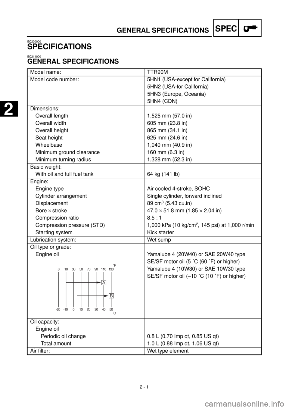
GENERAL SPECIFICATIONS
Model name: TTR90M
Model code number: 5HN1 (USA-except for California)
5HN2 (USA-for California)
5HN3 (Europe, Oceania)
5HN4 (CDN)
Dimensions:
Overall length 1,525 mm (57.0 in)
Overall width 605 mm (23.8 in)
Overall height 865 mm (34.1 in)
Seat height 625 mm (24.6 in)
Wheelbase 1,040 mm (40.9 in)
Minimum ground clearance 160 mm (6.3 in)
Minimum turning radius 1,328 mm (52.3 in)
Basic weight:
With oil and full fuel tank 64 kg (141 lb)
Engine:
Engine type Air cooled 4-stroke, SOHC
Cylinder arrangement Single cylinder, forward inclined
Displacement 89 cm
3
(5.43 cu.in)
Bore
´
stroke 47.0
´
51.8 mm (1.85
´
2.04 in)
Compression ratio 8.5 : 1
Compression pressure (STD) 1,000 kPa (10 kg/cm
2
, 145 psi) at 1,000 r/min
Starting system Kick starter
Lubrication system: Wet sump
Oil type or grade:
Engine oil
Yamalube 4 (20W40) or SAE 20W40 type
SE/SF motor oil (5 ˚C (60 ˚F) or higher)
Yamalube 4 (10W30) or SAE 10W30 type
SE/SF motor oil (–10 ˚C (10 ˚F) or higher)
Oil capacity:
Engine oil
Periodic oil change 0.8 L (0.70 Imp qt, 0.85 US qt)
Total amount 1.0 L (0.88 Imp qt, 1.06 US qt)
Air filter: Wet type element
0 10 30 50 70 90 110 130
-20 -10 01020
30 40 50
õ
˚F
˚C
GENERAL SPECIFICATIONS
2
Page 102 of 287
2 - 16
SPEC
CABLE ROUTING DIAGRAM
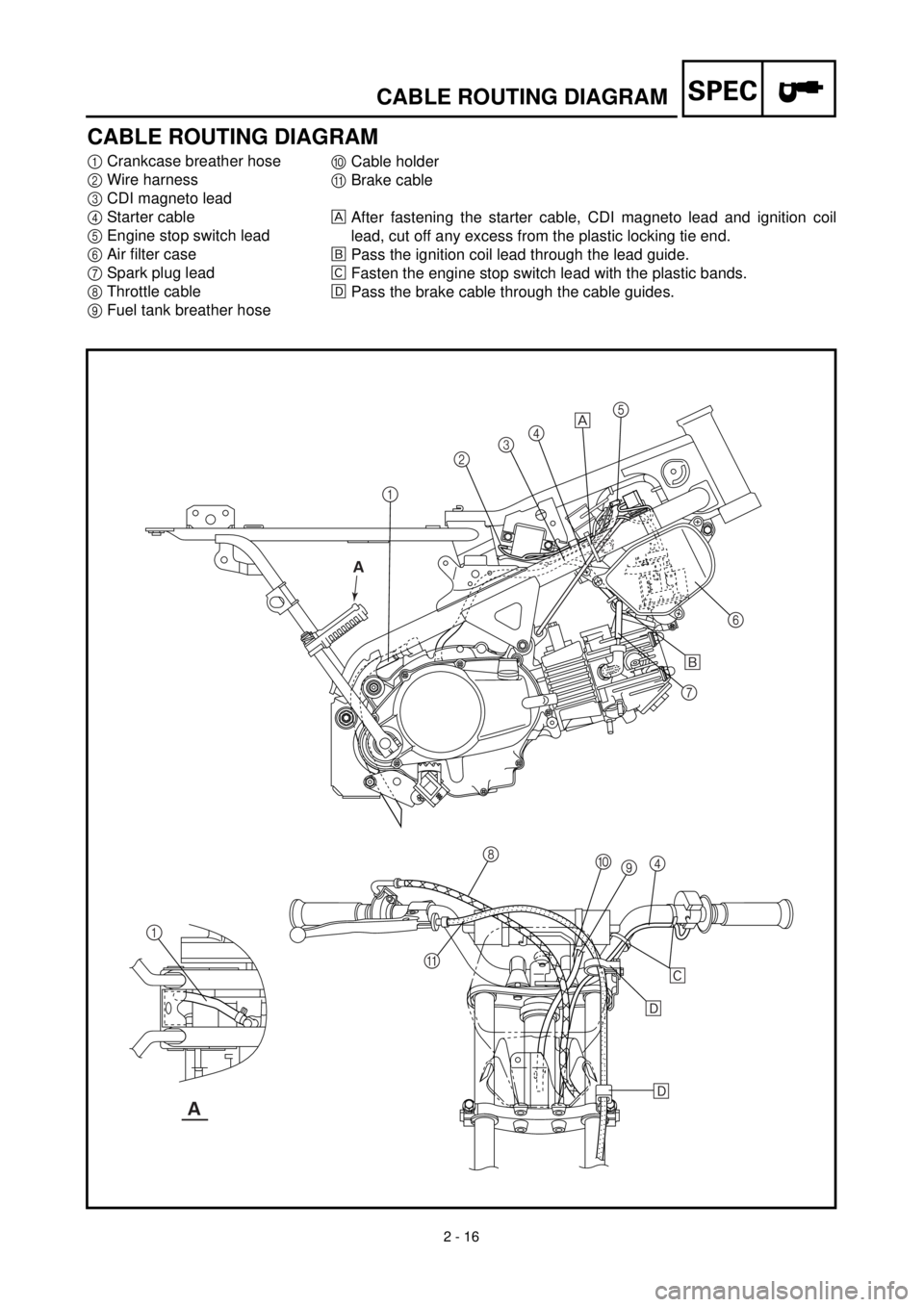
CABLE ROUTING DIAGRAM
1
Crankcase breather hose
2
Wire harness
3
CDI magneto lead
4
Starter cable
5
Engine stop switch lead
6
Air filter case
7
Spark plug lead
8
Throttle cable
9
Fuel tank breather hose
0
Cable holder
A
Brake cable
After fastening the starter cable, CDI magneto lead and ignition coil
lead, cut off any excess from the plastic locking tie end.
õ
Pass the ignition coil lead through the lead guide.
‚
Fasten the engine stop switch lead with the plastic bands.
ë
Pass the brake cable through the cable guides.
12345
6
7
8
9 0
4
A 1
õ
‚
ë
ë
A
A
Page 104 of 287
2 - 17
SPEC
CABLE ROUTING DIAGRAM
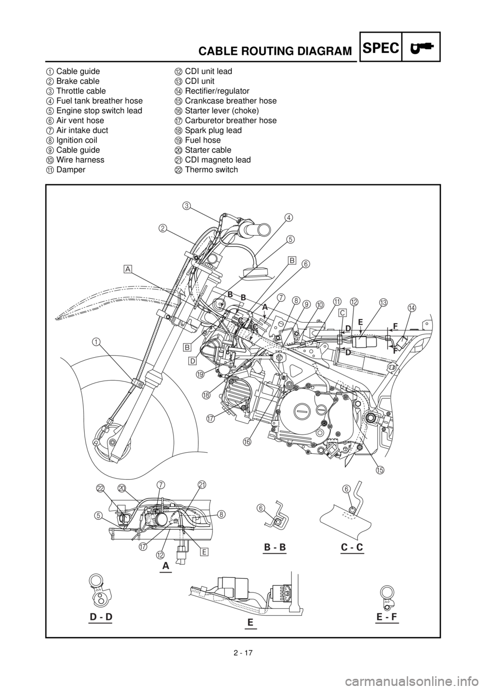
1
Cable guide
2
Brake cable
3
Throttle cable
4
Fuel tank breather hose
5
Engine stop switch lead
6
Air vent hose
7
Air intake duct
8
Ignition coil
9
Cable guide
0
Wire harness
A
Damper
B
CDI unit lead
C
CDI unit
D
Rectifier/regulator
E
Crankcase breather hose
F
Starter lever (choke)
G
Carburetor breather hose
H
Spark plug lead
I
Fuel hose
J
Starter cable
K
CDI magneto lead
L
Thermo switch
A
123
4
5
6
7
8
9
0A
C
D B
E F G H I
6
6 J L
5
G
B8 K
7 õ
‚
õ
ë
ä
B - B C - C
D - DE - FE
A A B
B B
B
C
C C
CE
B D
B D
F
F F F
Page 108 of 287
3 - 1
INSP
ADJ
MAINTENANCE INTERVALS/
PERIODIC MAINTENANCE AND LUBRICATION
EC300000
REGULAR INSPECTION AND ADJUSTMENTS
EC310022
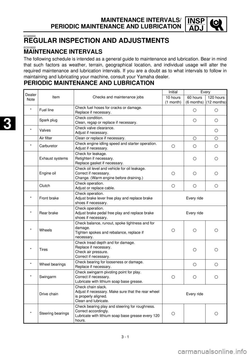
MAINTENANCE INTERVALS
The following schedule is intended as a general guide to maintenance and lubrication. Bear in mind
that such factors as weather, terrain, geographical location, and individual usage will alter the
required maintenance and lubrication intervals. If you are a doubt as to what intervals to follow in
maintaining and lubricating your machine, consult your Yamaha dealer.
PERIODIC MAINTENANCE AND LUBRICATION
Dealer
NoteItem Checks and maintenance jobsInitial Every
10 hours
(1 month)60 hours
(6 months)120 hours
(12 months)
* Fuel lineCheck fuel hoses for cracks or damage.
Replace if necessary.
Spark plugCheck condition.
Clean, regap or replace if necessary.
* ValvesCheck valve clearance.
Adjust if necessary.
Air filter Clean or replace if necessary.
* CarburetorCheck engine idling speed and starter operation.
Adjust if necessary.
Exhaust systemsCheck for leakage.
Retighten if necessary.
Replace gasket if necessary.
Engine oilCheck oil level and vehicle for oil leakage.
Correct if necessary.
Change. (Warm engine before draining.)
ClutchCheck operation.
Adjust or replace cable.
* Front brakeCheck operation.
Adjust brake lever free play and replace brake
shoes if necessary.Every ride
* Rear brakeCheck operation.
Adjust brake pedal free play and replace brake
shoes if necessary.Every ride
* WheelsCheck balance, runout, spoke tightness and for
damage.
Tighten spokes and rebalance, replace if
necessary.
* TiresCheck tread depth and for damage.
Replace if necessary.
Check air pressure.
Correct if necessary.
* Wheel bearingsCheck bearing for looseness or damage.
Replace if necessary.
* SwingarmCheck swingarm pivoting point for play.
Correct if necessary.
Lubricate with lithium soap base grease.
Drive chainCheck chain slack.
Adjust if necessary. Make sure that the rear wheel
is properly aligned.
Clean and lubricate.Every ride
* Steering bearingsCheck bearing play and steering for roughness.
Correct accordingly.
Lubricate with lithium soap base grease every 120
hours.
3
3
Page 109 of 287
3 - 2
INSP
ADJ
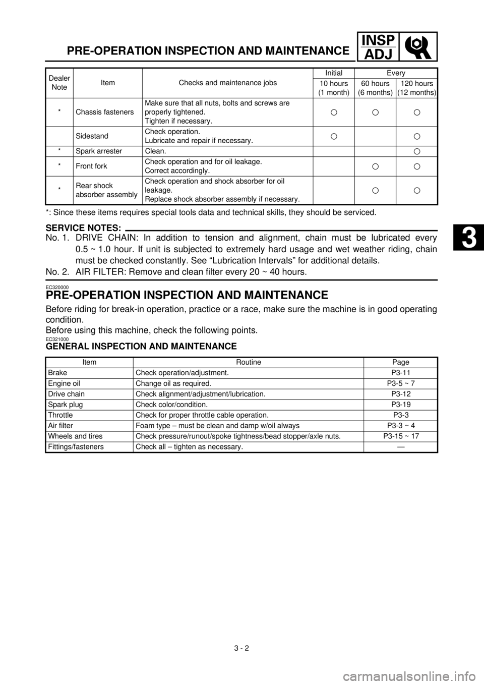
PRE-OPERATION INSPECTION AND MAINTENANCE
*: Since these items requires special tools data and technical skills, they should be serviced.
SERVICE NOTES:
No. 1. DRIVE CHAIN: In addition to tension and alignment, chain must be lubricated every
0.5 ~ 1.0 hour. If unit is subjected to extremely hard usage and wet weather riding, chain
must be checked constantly. See “Lubrication Intervals” for additional details.
No. 2. AIR FILTER: Remove and clean filter every 20 ~ 40 hours.
EC320000
PRE-OPERATION INSPECTION AND MAINTENANCE
Before riding for break-in operation, practice or a race, make sure the machine is in good operating
condition.
Before using this machine, check the following points.
EC321000
GENERAL INSPECTION AND MAINTENANCE
* Chassis fastenersMake sure that all nuts, bolts and screws are
properly tightened.
Tighten if necessary.
SidestandCheck operation.
Lubricate and repair if necessary.
* Spark arrester Clean.
* Front forkCheck operation and for oil leakage.
Correct accordingly.
*Rear shock
absorber assemblyCheck operation and shock absorber for oil
leakage.
Replace shock absorber assembly if necessary.
Item Routine Page
Brake Check operation/adjustment. P3-11
Engine oil Change oil as required. P3-5 ~ 7
Drive chain Check alignment/adjustment/lubrication. P3-12
Spark plug Check color/condition. P3-19
Throttle Check for proper throttle cable operation. P3-3
Air filter Foam type – must be clean and damp w/oil always P3-3 ~ 4
Wheels and tires Check pressure/runout/spoke tightness/bead stopper/axle nuts. P3-15 ~ 17
Fittings/fasteners Check all – tighten as necessary. —Dealer
NoteItem Checks and maintenance jobsInitial Every
10 hours
(1 month)60 hours
(6 months)120 hours
(12 months)
3