ECU YAMAHA TTR90 2001 Betriebsanleitungen (in German)
[x] Cancel search | Manufacturer: YAMAHA, Model Year: 2001, Model line: TTR90, Model: YAMAHA TTR90 2001Pages: 288, PDF-Größe: 15.39 MB
Page 7 of 288

WICHTIGER HINWEIS
Dieses Fahrzeug ist ausschließlich für den Ge-
brauch abseits öffentlicher Straßen durch jun-
ge Fahrer unter Beaufsichtigung von Erwach-
senen vorgesehen. Der Einsatz dieses
Fahrzeugs auf öffentlichen Straßen, Wegen
oder Schnellstraßen ist nicht gestattet.
Der Einsatz abseits der Straßen auf öffentli-
chem Gelände kann verboten sein. Bitte vor
Fahrtantritt die örtlichen Bestimmungen prü-
fen.
1. Kraftstoff ist leicht entzündlich.
Daher:
* Motor beim Auftanken immer abstel-
len.
* Beim Auftanken darauf achten, daß
kein Kraftstoff auf Motor, Krümmer
oder Schalldämpfer verschüttet
wird.
* Beim Auftanken darauf achten, daß
nicht geraucht wird und sich keine
offenen Flammen in der Nähe befin-
den.
2. Falls Kraftstoff geschluckt wurde,
große Mengen an Kraftstoffdampf ein-
geatmet wurden oder Kraftstoff in die
Augen gelangt ist, muß unverzüglich
ein Arzt aufgesucht werden. Falls
Kraftstoff auf Haut oder Kleidung
gelangt, sofort mit Wasser und Seife
abwaschen und die Kleidung wech-
seln.
3. Den Motor immer abstellen, wenn das
Fahrzeug unbeaufsichtigt ist. Beim
Parken des Fahrzeuges folgende
Punkte beachten:
* Motor und Auspuffanlage werden
sehr heiß. Darum so parken, daß
Fußgänger oder Kinder die heißen
Teile nicht versehentlich berühren
können.
* Das Fahrzeug nicht auf abschüssi-
gem oder weichem Untergrund
abstellen, damit es nicht umfallen
kann.
SICHERHEITSINFORMATION
REMARQUE IMPORTANTE
Ce véhicule est conçu uniquement pour une utilisa-
tion tout-terrain par des pilotes très jeunes roulant
sous la surveillance d’un adulte, après avoir reçu
les instructions nécessaires par un adulte. L’utilisa-
tion de cette machine sur la voie publique (rue,
route, autoroute, etc.) est interdite.
L’utilisation de ce véhicule sur des terrains publics
peut être illégale. Avant utilisation, prendre con-
naissance des réglementations locales.
1. L’ESSENCE EST UN PRODUIT TRES
INFLAMMABLE:
* Toujours couper le moteur avant de
faire le plein.
* Bien veiller à ne pas renverser d’essence
sur le moteur ou le tuyau et pot d’échap-
pement en faisant le plein.
* Ne pas faire le plein en fumant ou à
proximité d’une flamme.
2. En cas d’ingestion d’essence, d’inhalation
importante de vapeur d’essence ou d’écla-
boussure dans les yeux, consulter immé-
diatement un médecin. En cas
d’éclaboussure d’essence sur la peau ou
les vêtements, se laver immédiatement à
l’eau et au savon et changer de vêtements.
3. Toujours couper le moteur avant de lais-
ser le véhicule sans surveillance. Au
moment de se garer, être attentif aux
points suivants:
* Le moteur ainsi que les éléments du sys-
tème d’échappement risquent d’être
chauds. Garer le véhicule à un endroit
où les piétons et particulièrement les
enfants ne risquent pas de le toucher.
* Ne pas stationner dans une pente ou sur
un sol meuble où la machine pourrait se
renverser.
INFORMATION DE SECURITE
Page 11 of 288

SICHERHEITSINFORMATION
1. Das Fahrzeug nicht auf der Straße fahren.
2. Den Motor nicht in geschlossenen Räumen
starten.
3. Dieses Fahrzeug ist nur für eine Person
zugelassen. Zweipersonen-Betrieb ist nicht
gestattet.
4. Sicheres Fahren kann man lernen. Im
Zweifelsfall die Eltern fragen.
5. Beim Fahren immer einen Helm tragen.
1
Helm
2
Schutzbrille
3
Mundschutz
4
Motorrad-Handschuhe
5
Motorradstiefel
6
Motocross-Hose
7
Langärmeliges Trainingshemd
INFORMATION DE SECURITE
1. Ne pas rouler sur la route.
2. Ne pas faire tourner le moteur dans un bâti-
ment.
3. Il s’agit d’une moto à une seule place. Ne
jamais transporter de passager.
4. Il est important d’apprendre à conduire correc-
tement. Ne pas hésiter à poser des questions à
l’instructeur.
5. Toujours porter un casque, comme illustré,
lorsqu’on est à moto.
1
Casque
2
Lunettes
3
Protection pour la bouche
4
Gants
5
Bottes
6
Pantalon de motard
7
Une veste à longue manches
Page 15 of 288

COMMENT UTILISER CE
MANUEL
INFORMATIONS PARTICULIERE-
MENT IMPORTANTES
Le symbole d’alerte de sécurité signifie
ATTENTION! SOYEZ VIGILANT! VOTRE
SECURITE EST EN JEU!
Le non-respect des instructions AVERTISSE-
MENT peut entraîner de sérieuses blessures ou la
mort du pilote de la machine, d’un passant ou d’une
personne inspectant ou réparant la machine.
Un ATTENTION indique les procédures spéciales
qui doivent être suivies pour éviter d’endommager
la machine.
N.B.:
Un N.B. fournit les renseignements nécessaires
pour rendre les procédures plus faciles ou plus clai-
res.
TROUVER LA PAGE RECHERCHEE
1. Ce manuel comprend 6 chapitres: “Rensei-
gnements généraux”, “Caractéristiques”,
“Contrôles et réglages courants”, “Moteur”,
“Partie cycle” et “Partie électrique”.
2. La table des matières se trouve au début du
manuel.
Regarder la disposition générale du manuel
avant de rechercher le chapitre et l’article
désirés.
Arquer le manuel à son bord, de la manière
indiquée, pour trouver le symbole de devant
désiré et passer à une page de la description et
l’article désirés.
AVERTISSEMENT
ATTENTION:
BENUTZERHINWEISE
KENNZEICHNUNG
WICHTIGER HINWEISE
Das Ausrufezeichen bedeutet: “GEFAHR!
Achten Sie auf Ihre Sicherheit!”
Ein Mißachten dieser Warnhinweise bringt
Fahrer, Mechaniker und andere Personen in
Verletzungs- oder Lebensgefahr.
Hierunter sind Vorsichtsmaßnahmen zum
Schutz des Fahrzeugs vor Schäden aufge-
führt.
HINWEISE:
Ein HINWEIS gibt Zusatzinformationen und
Tips, um bestimmte Vorgänge oder Arbeiten
zu vereinfachen.
INFORMATION AUFFINDEN
1. Diese Anleitung umfaßt sechs Kapitel: 1.
Allgemeine Angaben – 2. Technische
Daten – 3. Regelmäßige Inspektionen
und Einstellarbeiten – 4. Motor – 5. Fahr-
werk – 6. Elektrische Anlage.
2. Dem ersten Kapitel geht ein Inhaltver-
zeichnis voran. Machen Sie sich mit dem
Inhalt und Aufbau der Anleitung vertraut,
bevor Sie nach bestimmten Angaben su-
chen. Halten Sie das Buch wie in der Ab-
bildung gezeigt, um das Auffinden der
einzelnen Kapitel zu erleichtern.
WARNUNG
ACHTUNG:
Page 37 of 288
GEN
INFO
1 - 7
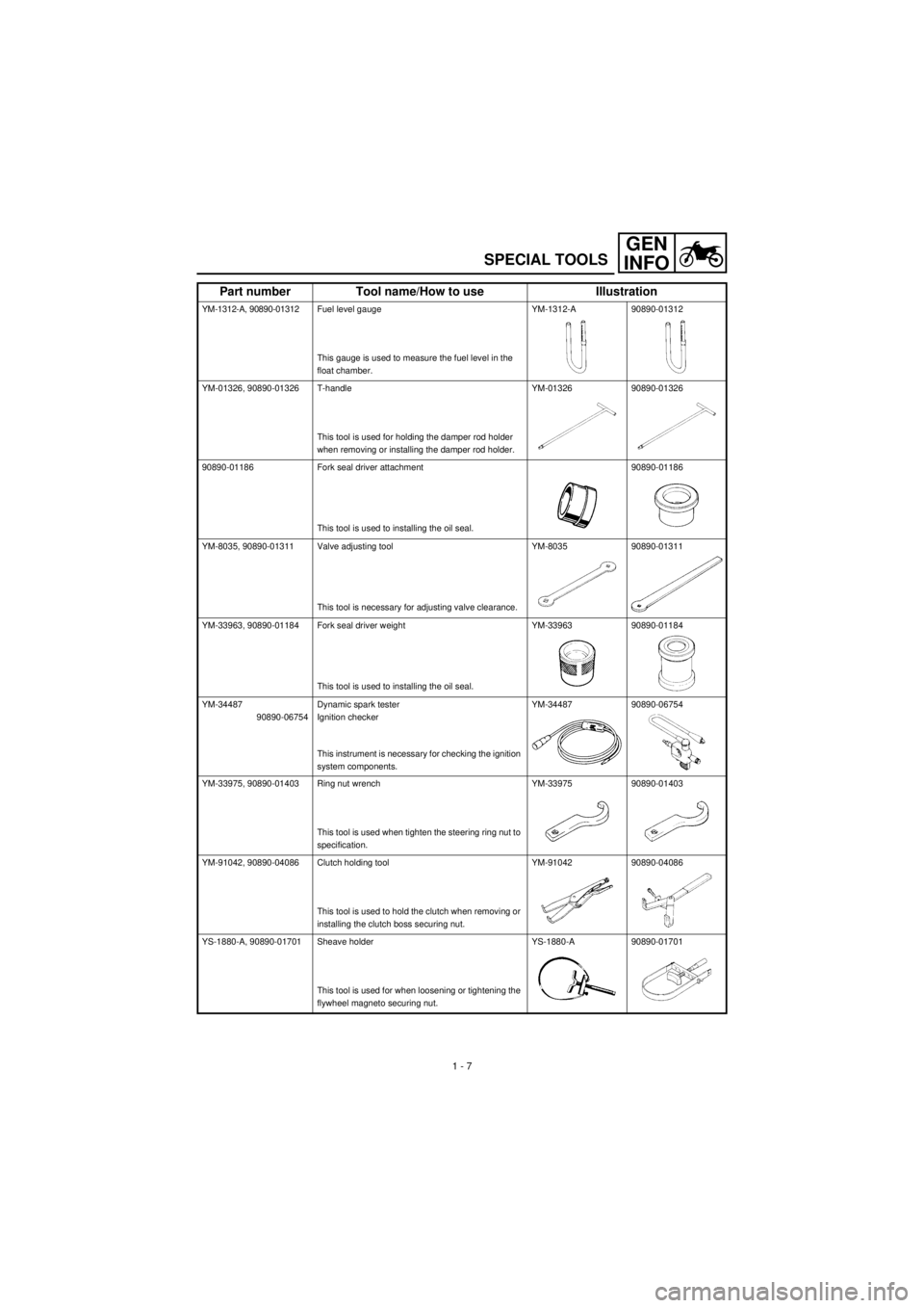
SPECIAL TOOLS
YM-1312-A, 90890-01312Fuel level gauge
This gauge is used to measure the fuel level in the
float chamber.YM-1312-A 90890-01312
YM-01326, 90890-01326 T-handle
This tool is used for holding the damper rod holder
when removing or installing the damper rod holder.YM-01326 90890-01326
90890-01186 Fork seal driver attachment
This tool is used to installing the oil seal.90890-01186
YM-8035, 90890-01311 Valve adjusting tool
This tool is necessary for adjusting valve clearance.YM-8035 90890-01311
YM-33963, 90890-01184 Fork seal driver weight
This tool is used to installing the oil seal.YM-33963 90890-01184
YM-34487
90890-06754Dynamic spark tester
Ignition checker
This instrument is necessary for checking the ignition
system components.YM-34487 90890-06754
YM-33975, 90890-01403 Ring nut wrench
This tool is used when tighten the steering ring nut to
specification.YM-33975 90890-01403
YM-91042, 90890-04086 Clutch holding tool
This tool is used to hold the clutch when removing or
installing the clutch boss securing nut.YM-91042 90890-04086
YS-1880-A, 90890-01701 Sheave holder
This tool is used for when loosening or tightening the
flywheel magneto securing nut.YS-1880-A 90890-01701
Part number Tool name/How to use Illustration
Page 52 of 288
GEN
INFO
1 - 12
STARTING AND OPERATION
STARTING AND OPERATION
CAUTION:
Prior to operating the machine, perform
steps listed in pre-operation check list.
WARNING
Never start your engine or let it run for any
length of time in a closed area. The exhaust
fumes are poisonous and can cause loss of
consciousness and death within a short
time. Always operate your machine in an
area with adequate ventilation.
STARTING A COLD ENGINE
WARNING
Before starting the engine, be sure to shift
the transmission into neutral.
1. Turn the fuel cock to “ON”.
2. Operate the starter (choke) and com-
pletely close the throttle grip.
3. Slide the “ENGINE STOP” switch to the
“”.
4. Kick the kick starter with full strength to
start the engine.
5. After the engine starts, warm up for one
or two minutes. Make sure the stater
(choke) is returned to the original position
before riding.
STARTING A WARM ENGINE
To start a warm engine, refer to the “Starting a
cold engine” section. The starter (choke)
should not be used. The throttle should be
opened slightly.
CAUTION:
See “Engine break-in Section” prior to
operating engine for the first time.WARMING UP
To get maximum engine life, always “warm-up”
the engine before starting off. Never acceler-
ate hard with a cold engine! To see whether or
not the engine is warm, see if it responds to
throttle normally with the stater (choke) turned
off.
WARNING
Before starting off, be sure to turn up or
remove the side stand.
Failure to retract the side stand completely
can result in a serious accident when you
try to turn a corner.
ENGINE BREAK-IN
Brake-in is important to better fit the moving
and sliding parts as well as the installed parts.
It is also important to accustom the rider to the
machine better.
Avoid full-throttle run on a new machine for the
first 5 hours.
After the trial run, check for loose parts, oil
leakage and other problems.
Make full inspection and adjustment especially
of slack cables and drive chain and loose
spokes.
CAUTION:
After the break-in period, check every fit-
ting and fastener for looseness.
If any loose is found, retighten it securely.
Page 186 of 288
4 - 20
ENG
VALVES AND VALVE SPRINGS
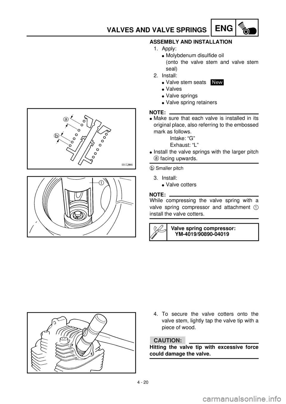
ASSEMBLY AND INSTALLATION
1. Apply:
l
Molybdenum disulfide oil
(onto the valve stem and valve stem
seal)
2. Install:
l
Valve stem seats
l
Valves
l
Valve springs
l
Valve spring retainers
NOTE:
l
Make sure that each valve is installed in its
original place, also referring to the embossed
mark as follows.
Intake: “G”
Exhaust: “L”
l
Install the valve springs with the larger pitch
a
facing upwards.
b
Smaller pitch
New
3. Install:
l
Valve cotters
NOTE:
While compressing the valve spring with a
valve spring compressor and attachment
1
install the valve cotters.
Valve spring compressor:
YM-4019/90890-04019
4. To secure the valve cotters onto the
valve stem, lightly tap the valve tip with a
piece of wood.
CAUTION:
Hitting the valve tip with excessive force
could damage the valve.
Page 240 of 288
5 - 1
CHAS
EC500000
CHASSIS
FRONT WHEEL AND REAR WHEEL
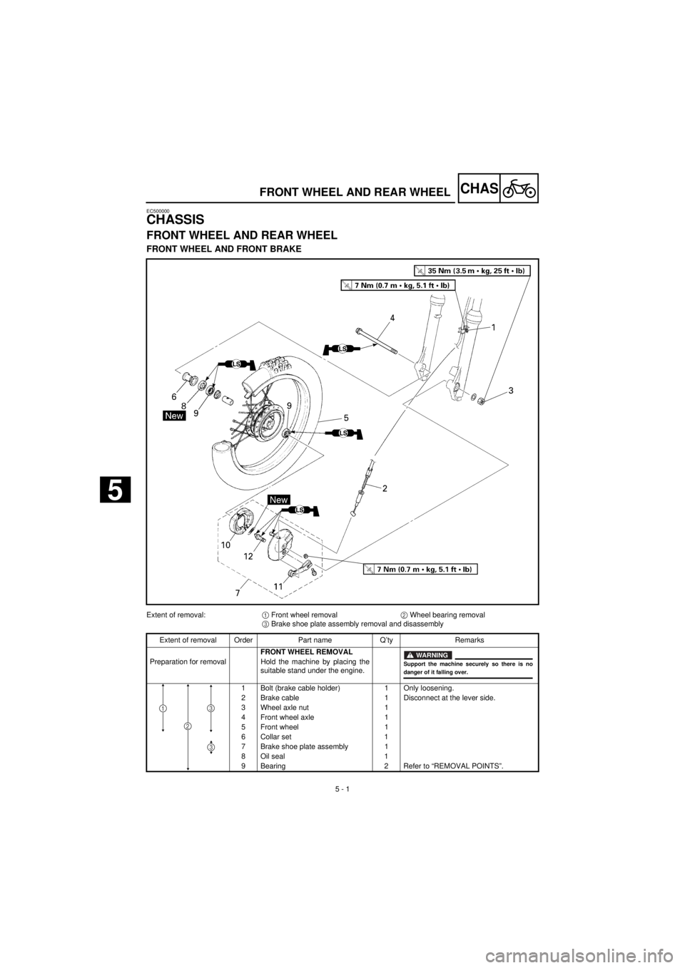
FRONT WHEEL AND FRONT BRAKE
Extent of removal:
1
Front wheel removal
2
Wheel bearing removal
3
Brake shoe plate assembly removal and disassembly
Extent of removal Order Part name Q’ty Remarks
FRONT WHEEL REMOVAL
Preparation for removal Hold the machine by placing the
suitable stand under the engine.
1 Bolt (brake cable holder) 1 Only loosening.
2 Brake cable 1 Disconnect at the lever side.
3 Wheel axle nut 1
4 Front wheel axle 1
5 Front wheel 1
6 Collar set 1
7 Brake shoe plate assembly 1
8 Oil seal 1
9Bearing
2Refer to “REMOVAL POINTS”.
WARNING
Support the machine securely so there is nodanger of it falling over.
2
31
3
FRONT WHEEL AND REAR WHEEL
5
Page 244 of 288
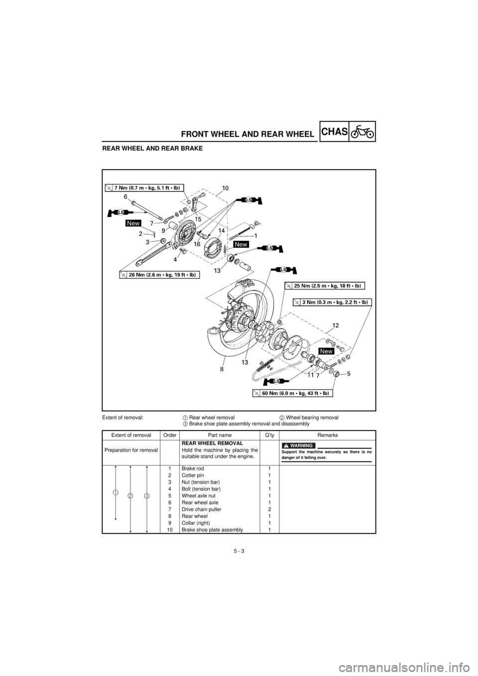
5 - 3
CHAS
FRONT WHEEL AND REAR WHEEL
REAR WHEEL AND REAR BRAKE
Extent of removal:
1
Rear wheel removal
2
Wheel bearing removal
3
Brake shoe plate assembly removal and disassembly
Extent of removal Order Part name Q’ty Remarks
REAR WHEEL REMOVAL
Preparation for removal Hold the machine by placing the
suitable stand under the engine.
1 Brake rod 1
2 Cotter pin 1
3 Nut (tension bar) 1
4 Bolt (tension bar) 1
5 Wheel axle nut 1
6 Rear wheel axle 1
7 Drive chain puller 2
8 Rear wheel 1
9 Collar (right) 1
10 Brake shoe plate assembly 1
WARNING
Support the machine securely so there is nodanger of it falling over.
231
Page 250 of 288
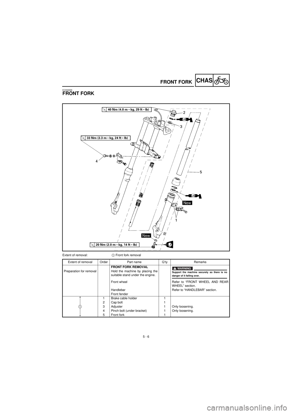
5 - 6
CHAS
FRONT FORK
EC550000
FRONT FORK
Extent of removal:
1
Front fork removal
Extent of removal Order Part name Q’ty Remarks
FRONT FORK REMOVAL
Preparation for removal Hold the machine by placing the
suitable stand under the engine.
Front wheel Refer to “FRONT WHEEL AND REAR
WHEEL” section.
Handlebar Refer to “HANDLEBAR” section.
Front fender
1 Brake cable holder 1
2 Cap bolt 1
3 Adjuster 1 Only loosening.
4 Pinch bolt (under bracket) 1 Only loosening.
5 Front fork 1
WARNING
Support the machine securely so there is nodanger of it falling over.
1
Page 258 of 288
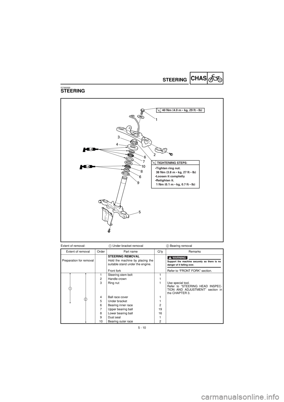
5 - 10
CHAS
STEERING
EC560000
STEERING
LS
LS
T R..TIGHTENING STEPS:
•Tighten ring nut.
38 Nm (3.8 m • kg, 27 ft • Ib)
•Loosen it completly
•Retighten it.
1 Nm (0.1 m • kg, 0.7 ft • Ib)
T R..40 Nm (4.0 m • kg, 29 ft • Ib)
5 9681076 43
21
Extent of removal:
1
Under bracket removal
2
Bearing removal
Extent of removal Order Part name Q’ty Remarks
STEERING REMOVAL
Preparation for removal Hold the machine by placing the
suitable stand under the engine.
Front fork Refer to “FRONT FORK” section.
1 Steering stem bolt 1
2 Handle crown 1
3 Ring nut 1 Use special tool.
Refer to “STEERING HEAD INSPEC-
TION AND ADJUSTMENT” section in
the CHAPTER 3.
4 Ball race cover 1
5 Under bracket 1
6 Bearing inner race 2
7 Upper bearing ball 19
8 Lower bearing ball 16
9 Dust seal 1
10 Bearing outer race 2
WARNING
Support the machine securely so there is nodanger of it falling over.
2
1