engine oil YAMAHA TTR90 2002 Betriebsanleitungen (in German)
[x] Cancel search | Manufacturer: YAMAHA, Model Year: 2002, Model line: TTR90, Model: YAMAHA TTR90 2002Pages: 288, PDF-Größe: 15.07 MB
Page 109 of 288
3 - 2
INSP
ADJ
PRE-OPERATION INSPECTION AND MAINTENANCE
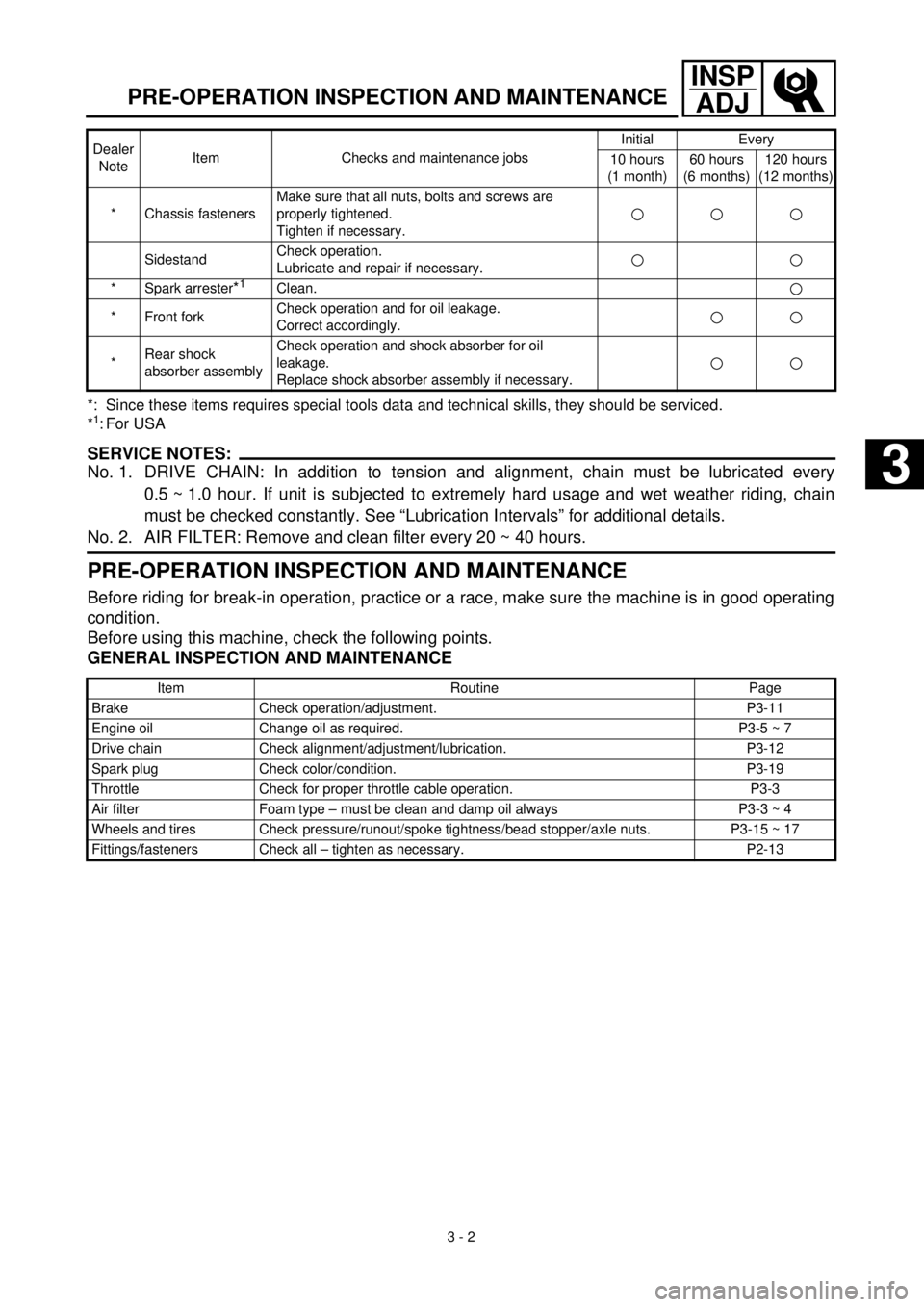
*: Since these items requires special tools data and technical skills, they should be serviced.
*1: For USA
SERVICE NOTES:
No. 1. DRIVE CHAIN: In addition to tension and alignment, chain must be lubricated every
0.5 ~ 1.0 hour. If unit is subjected to extremely hard usage and wet weather riding, chain
must be checked constantly. See “Lubrication Intervals” for additional details.
No. 2. AIR FILTER: Remove and clean filter every 20 ~ 40 hours.
PRE-OPERATION INSPECTION AND MAINTENANCE
Before riding for break-in operation, practice or a race, make sure the machine is in good operating
condition.
Before using this machine, check the following points.
GENERAL INSPECTION AND MAINTENANCE
* Chassis fastenersMake sure that all nuts, bolts and screws are
properly tightened.
Tighten if necessary.
SidestandCheck operation.
Lubricate and repair if necessary.
* Spark arrester*1Clean.
* Front forkCheck operation and for oil leakage.
Correct accordingly.
*Rear shock
absorber assemblyCheck operation and shock absorber for oil
leakage.
Replace shock absorber assembly if necessary.
Item Routine Page
Brake Check operation/adjustment. P3-11
Engine oil Change oil as required. P3-5 ~ 7
Drive chain Check alignment/adjustment/lubrication. P3-12
Spark plug Check color/condition. P3-19
Throttle Check for proper throttle cable operation. P3-3
Air filter Foam type – must be clean and damp oil always P3-3 ~ 4
Wheels and tires Check pressure/runout/spoke tightness/bead stopper/axle nuts. P3-15 ~ 17
Fittings/fasteners Check all – tighten as necessary. P2-13Dealer
NoteItem Checks and maintenance jobsInitial Every
10 hours
(1 month)60 hours
(6 months)120 hours
(12 months)
3
Page 116 of 288
3 - 4
INSP
ADJ
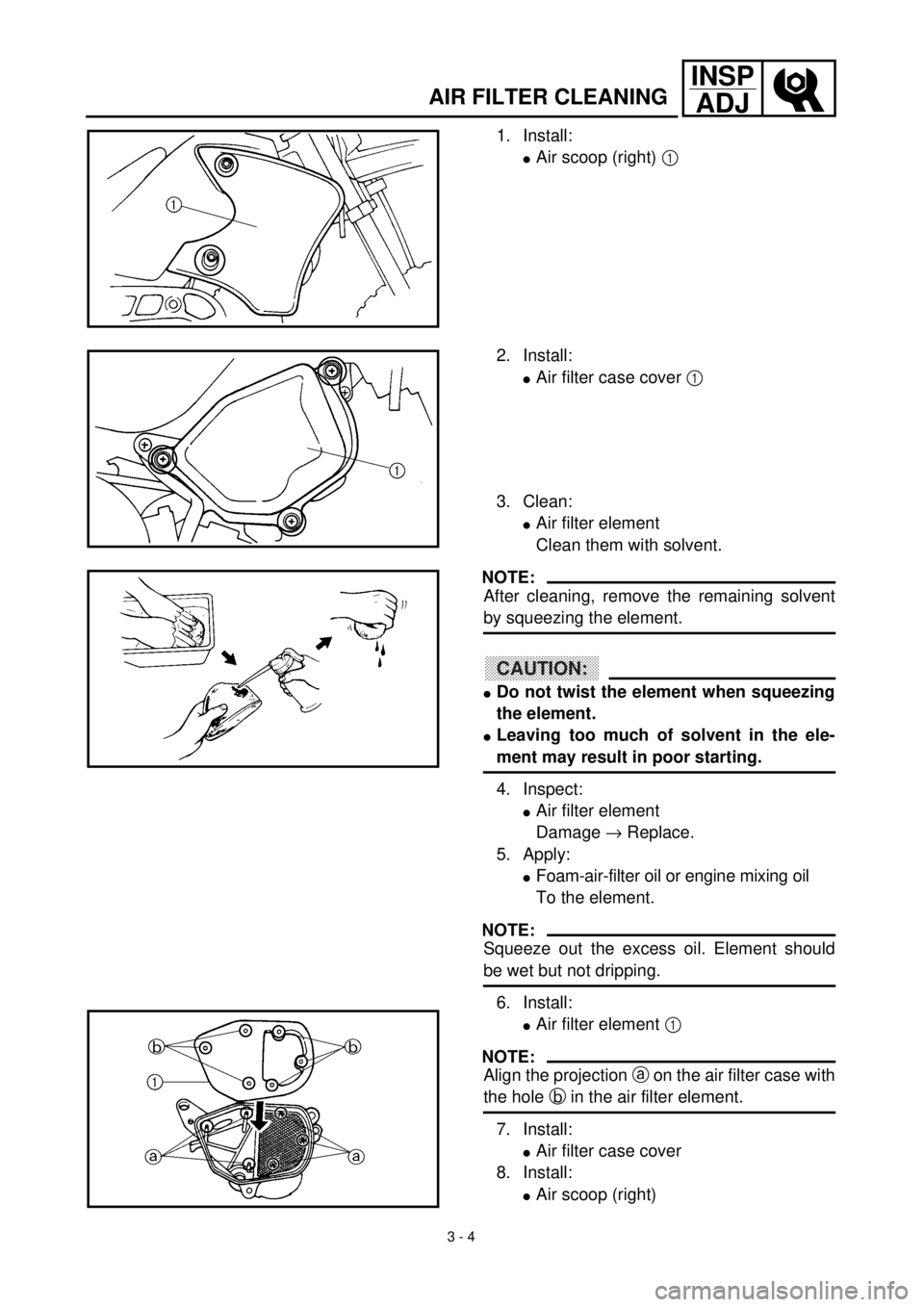
AIR FILTER CLEANING
1. Install:
lAir scoop (right) 1
2. Install:
lAir filter case cover 1
3. Clean:
lAir filter element
Clean them with solvent.
NOTE:
After cleaning, remove the remaining solvent
by squeezing the element.
CAUTION:
lDo not twist the element when squeezing
the element.
lLeaving too much of solvent in the ele-
ment may result in poor starting.
4. Inspect:
lAir filter element
Damage ® Replace.
5. Apply:
lFoam-air-filter oil or engine mixing oil
To the element.
NOTE:
Squeeze out the excess oil. Element should
be wet but not dripping.
6. Install:
lAir filter element 1
NOTE:
Align the projection a on the air filter case with
the hole b in the air filter element.
7. Install:
lAir filter case cover
8. Install:
lAir scoop (right)
Page 118 of 288
3 - 5
INSP
ADJ
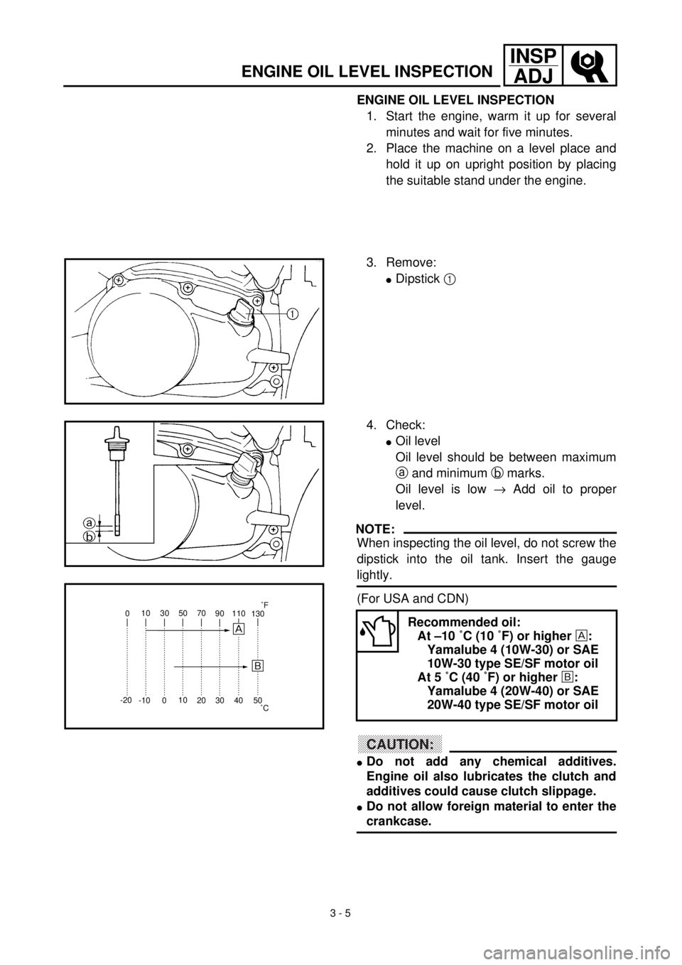
ENGINE OIL LEVEL INSPECTION
1. Start the engine, warm it up for several
minutes and wait for five minutes.
2. Place the machine on a level place and
hold it up on upright position by placing
the suitable stand under the engine.
3. Remove:
lDipstick 1
4. Check:
lOil level
Oil level should be between maximum
a and minimum b marks.
Oil level is low ® Add oil to proper
level.
NOTE:
When inspecting the oil level, do not screw the
dipstick into the oil tank. Insert the gauge
lightly.
(For USA and CDN)
CAUTION:
lDo not add any chemical additives.
Engine oil also lubricates the clutch and
additives could cause clutch slippage.
lDo not allow foreign material to enter the
crankcase.
Recommended oil:
At –10 ˚C (10 ˚F) or higher :
Yamalube 4 (10W-30) or SAE
10W-30 type SE/SF motor oil
At 5 ˚C (40 ˚F) or higher õ:
Yamalube 4 (20W-40) or SAE
20W-40 type SE/SF motor oil010 30 50 70
90110
130
-20
-10010
20 30 40
50
õ
˚C˚F
ENGINE OIL LEVEL INSPECTION
Page 120 of 288
3 - 6
INSP
ADJ
ENGINE OIL REPLACEMENT
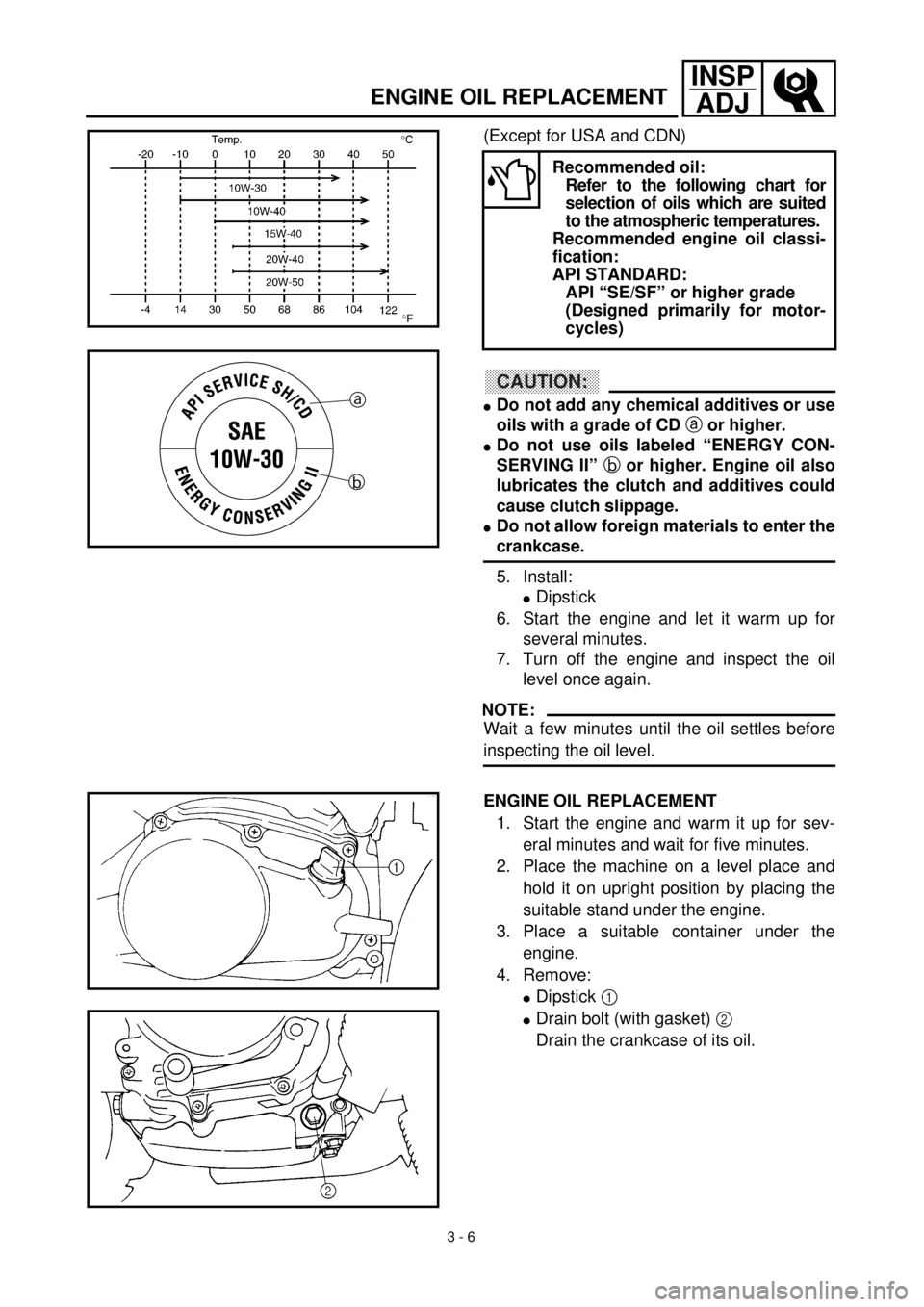
(Except for USA and CDN)
CAUTION:
lDo not add any chemical additives or use
oils with a grade of CD a or higher.
lDo not use oils labeled “ENERGY CON-
SERVING II” b or higher. Engine oil also
lubricates the clutch and additives could
cause clutch slippage.
lDo not allow foreign materials to enter the
crankcase.
5. Install:
lDipstick
6. Start the engine and let it warm up for
several minutes.
7. Turn off the engine and inspect the oil
level once again.
NOTE:
Wait a few minutes until the oil settles before
inspecting the oil level.
ENGINE OIL REPLACEMENT
1. Start the engine and warm it up for sev-
eral minutes and wait for five minutes.
2. Place the machine on a level place and
hold it on upright position by placing the
suitable stand under the engine.
3. Place a suitable container under the
engine.
4. Remove:
lDipstick 1
lDrain bolt (with gasket) 2
Drain the crankcase of its oil.
Recommended oil:
Refer to the following chart for
selection of oils which are suited
to the atmospheric temperatures.
Recommended engine oil classi-
fication:
API STANDARD:
API “SE/SF” or higher grade
(Designed primarily for motor-
cycles)
a
b
Page 122 of 288
3 - 7
INSP
ADJ
PILOT AIR SCREW ADJUSTMENT
5. Install:
lGasket
lDrain bolt
New
T R..20 Nm (2.0 m · kg, 14 ft · lb)
6. Fill:
lCrankcase
Oil quantity:
Periodic oil change:
0.8 L (0.70 Imp qt, 0.85 US qt)
7. Install:
lDipstick
8. Inspect:
lEngine (for oil leaks)
lOil level
Refer to “ENGINE OIL LEVEL INSPEC-
TION”.
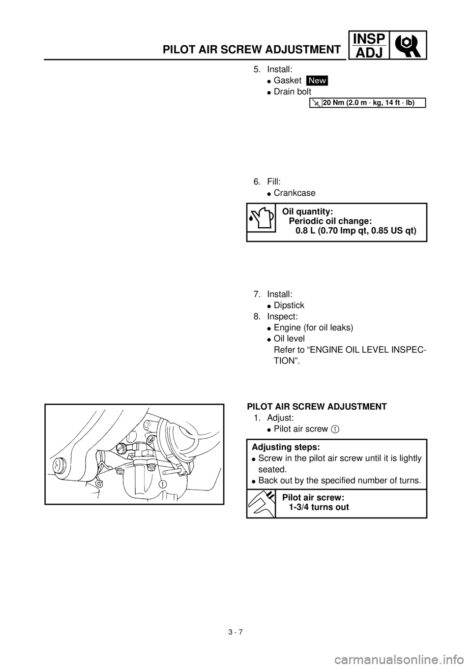
PILOT AIR SCREW ADJUSTMENT
1. Adjust:
lPilot air screw 1
Adjusting steps:
lScrew in the pilot air screw until it is lightly
seated.
lBack out by the specified number of turns.
Pilot air screw:
1-3/4 turns out
Page 134 of 288
3 - 13
INSP
ADJFRONT FORK INSPECTION/REAR SHOCK ABSORBER INSPECTION/
REAR SHOCK ABSORBER SPRING PRELOAD ADJUSTMENT
lTighten the wheel axle nut while pushing
down the drive chain.
T R..
Axle nut:
60 Nm (6.0 m • kg, 43 ft • lb)
EC36C000
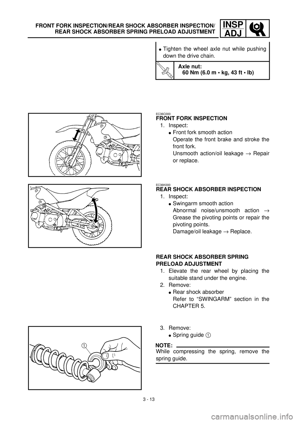
FRONT FORK INSPECTION
1. Inspect:
lFront fork smooth action
Operate the front brake and stroke the
front fork.
Unsmooth action/oil leakage ® Repair
or replace.
EC36K000
REAR SHOCK ABSORBER INSPECTION
1. Inspect:
lSwingarm smooth action
Abnormal noise/unsmooth action ®
Grease the pivoting points or repair the
pivoting points.
Damage/oil leakage ® Replace.
REAR SHOCK ABSORBER SPRING
PRELOAD ADJUSTMENT
1. Elevate the rear wheel by placing the
suitable stand under the engine.
2. Remove:
lRear shock absorber
Refer to “SWINGARM” section in the
CHAPTER 5.
3. Remove:
lSpring guide 1
NOTE:
While compressing the spring, remove the
spring guide.
Page 168 of 288
4 - 11
ENGCYLINDER HEAD
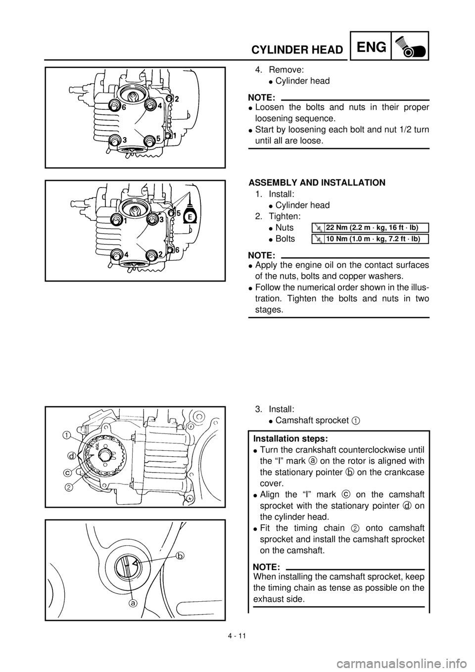
4. Remove:
lCylinder head
NOTE:
lLoosen the bolts and nuts in their proper
loosening sequence.
lStart by loosening each bolt and nut 1/2 turn
until all are loose.
ASSEMBLY AND INSTALLATION
1. Install:
lCylinder head
2. Tighten:
lNuts
lBolts
NOTE:
lApply the engine oil on the contact surfaces
of the nuts, bolts and copper washers.
lFollow the numerical order shown in the illus-
tration. Tighten the bolts and nuts in two
stages.
T R..22 Nm (2.2 m · kg, 16 ft · lb)
T R..10 Nm (1.0 m · kg, 7.2 ft · lb)
3. Install:
lCamshaft sprocket 1
Installation steps:
lTurn the crankshaft counterclockwise until
the “I” mark a on the rotor is aligned with
the stationary pointer b on the crankcase
cover.
lAlign the “I” mark c on the camshaft
sprocket with the stationary pointer d on
the cylinder head.
lFit the timing chain 2 onto camshaft
sprocket and install the camshaft sprocket
on the camshaft.
NOTE:
When installing the camshaft sprocket, keep
the timing chain as tense as possible on the
exhaust side.
Page 174 of 288
4 - 14
ENGCAMSHAFT AND ROCKER ARMS
REMOVAL POINTS
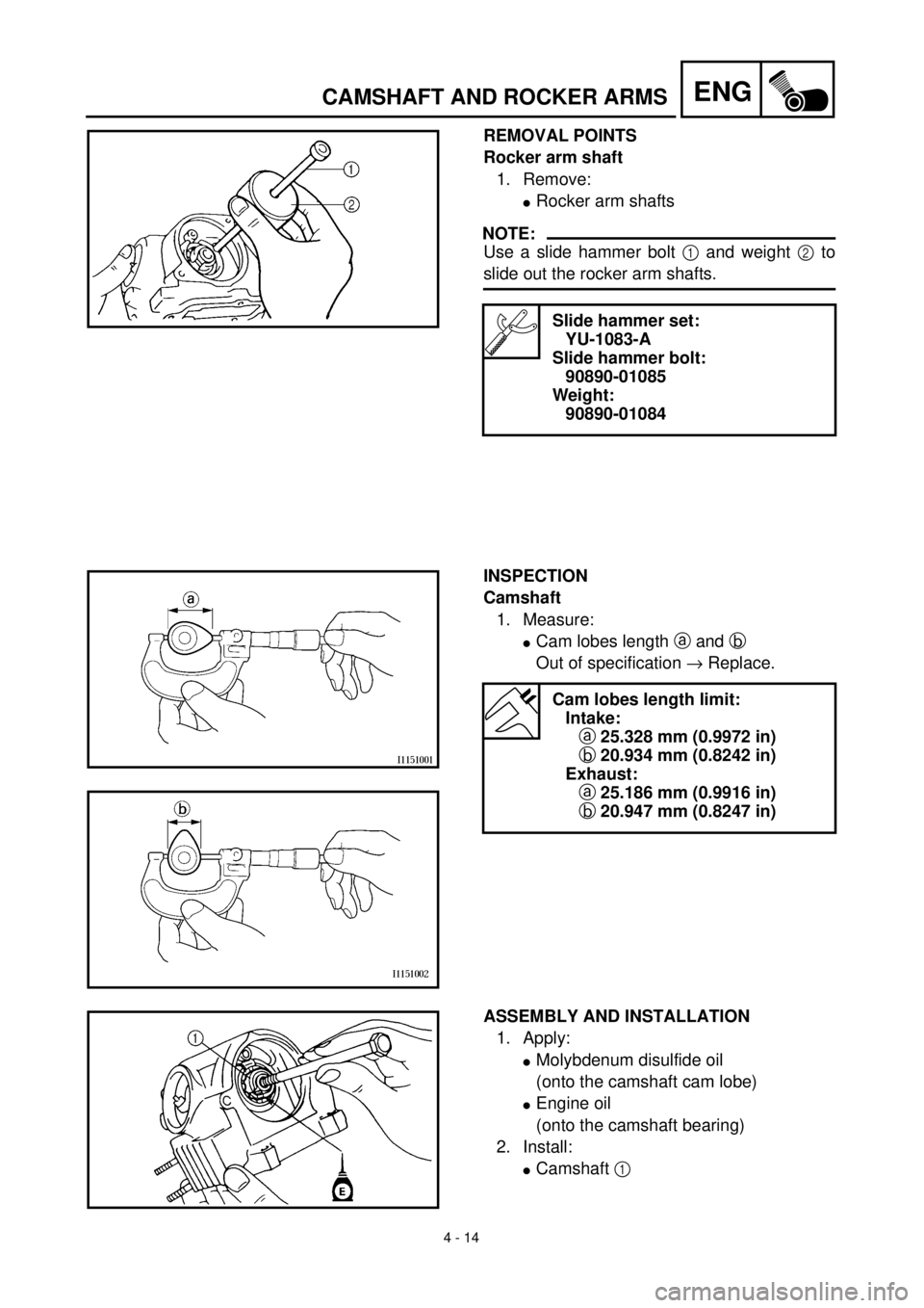
Rocker arm shaft
1. Remove:
lRocker arm shafts
NOTE:
Use a slide hammer bolt 1 and weight 2 to
slide out the rocker arm shafts.
Slide hammer set:
YU-1083-A
Slide hammer bolt:
90890-01085
Weight:
90890-01084
INSPECTION
Camshaft
1. Measure:
lCam lobes length a and b
Out of specification ® Replace.
Cam lobes length limit:
Intake:
a 25.328 mm (0.9972 in)
b 20.934 mm (0.8242 in)
Exhaust:
a 25.186 mm (0.9916 in)
b 20.947 mm (0.8247 in)
ASSEMBLY AND INSTALLATION
1. Apply:
lMolybdenum disulfide oil
(onto the camshaft cam lobe)
lEngine oil
(onto the camshaft bearing)
2. Install:
lCamshaft 1
Page 196 of 288
4 - 25
ENGCYLINDER AND PISTON
Piston pin
1. Inspect:
lPiston pin
Blue discoloration/grooves ®
Replace, then inspect the lubrication
system.
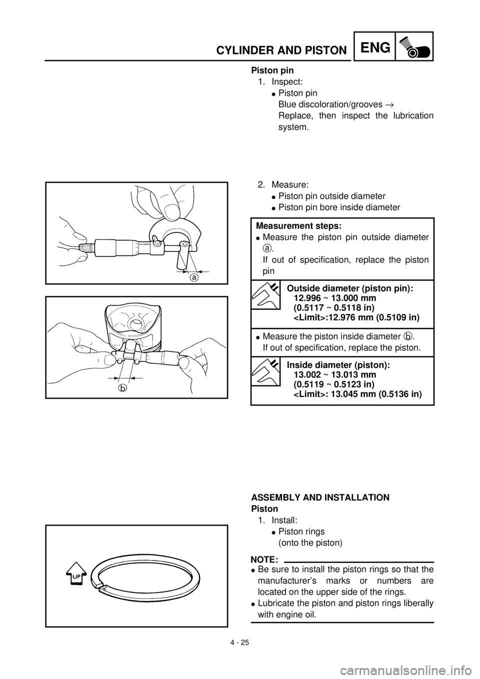
2. Measure:
lPiston pin outside diameter
lPiston pin bore inside diameter
ASSEMBLY AND INSTALLATION
Piston
1. Install:
lPiston rings
(onto the piston)
NOTE:
lBe sure to install the piston rings so that the
manufacturer’s marks or numbers are
located on the upper side of the rings.
lLubricate the piston and piston rings liberally
with engine oil. Measurement steps:
lMeasure the piston pin outside diameter
a.
If out of specification, replace the piston
pin
Outside diameter (piston pin):
12.996 ~ 13.000 mm
(0.5117 ~ 0.5118 in)
lMeasure the piston inside diameter b.
If out of specification, replace the piston.
Inside diameter (piston):
13.002 ~ 13.013 mm
(0.5119 ~ 0.5123 in)
Page 198 of 288
4 - 26
ENGCYLINDER AND PISTON
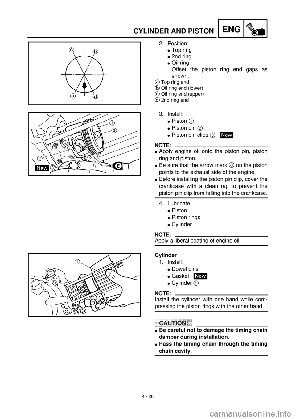
2. Position:
lTop ring
l2nd ring
lOil ring
Offset the piston ring end gaps as
shown.
aTop ring end
bOil ring end (lower)
cOil ring end (upper)
d2nd ring end
3. Install:
lPiston 1
lPiston pin 2
lPiston pin clips 3
NOTE:
lApply engine oil onto the piston pin, piston
ring and piston.
lBe sure that the arrow mark a on the piston
points to the exhaust side of the engine.
lBefore installing the piston pin clip, cover the
crankcase with a clean rag to prevent the
piston pin clip from falling into the crankcase.
4. Lubricate:
lPiston
lPiston rings
lCylinder
NOTE:
Apply a liberal coating of engine oil.
New
Cylinder
1. Install:
lDowel pins
lGasket
lCylinder 1
NOTE:
Install the cylinder with one hand while com-
pressing the piston rings with the other hand.
CAUTION:
lBe careful not to damage the timing chain
damper during installation.
lPass the timing chain through the timing
chain cavity.
New