fuel YAMAHA TTR90 2002 Betriebsanleitungen (in German)
[x] Cancel search | Manufacturer: YAMAHA, Model Year: 2002, Model line: TTR90, Model: YAMAHA TTR90 2002Pages: 288, PDF-Größe: 15.07 MB
Page 63 of 288

SPEC
2 - 8
Crankshaft:
Crank width “A” 42.95 ~ 43.00 mm
(1.691 ~ 1.693 in)----
Runout limit C ---- 0.03 mm
(0.0012 in)
Big end side clearance “D” 0.10 ~ 0.40 mm
(0.0039 ~ 0.0157 in)0.50 mm
(0.02 in)
Big end radial clearance “E” 0.010 ~ 0.025 mm
(0.0004 ~ 0.0010 in)0.05 mm
(0.002 in)
Clutch:
Friction plate thickness 2.7 ~ 2.9 mm
(0.106 ~ 0.114 in)2.6 mm
(0.102 in)
Quantity 5 ----
Clutch plate thickness 1.1 ~ 1.3 mm (0.043 ~ 0.051 in) ----
Quantity 4 ----
Warp limit ---- 0.2 mm
(0.008 in)
Clutch spring free length 26.2 mm (1.03 in) 24.2 mm
(0.95 in)
Quantity 4 ----
Clutch release method Inner push, cam push ----
Push rod bending limit ---- 0.5 mm
(0.02 in)
Automatic centrifugal clutch: ----
Clutch-in revolution 2,160 ~ 2,560 r/min ----
Clutch-stall revolution 3,300 ~ 3,800 r/min
Shifter:
Shifter type Cam drum and guide bar ----
Kick starter:
Type Ratchet type ----
Kick clip friction force 5.8 ~ 14.7 N
(0.59 ~ 1.50 kg, 1.3 ~ 3.3 lb)
Carburetor:
I. D. mark 5HN1 01 ----
Main jet (M.J) #90 ----
Main air jet (M.A.J) ø 1.1 ----
Jet needle (J.N) 4E9-2 ----
Cutaway (C.A) 2.5 ----
Pilot outlet (P.O) ø 1.0 ´ 2.0 ----
Pilot jet (P.J) #12.5 ----
Valve seat size (V.S) ø 1.5 ----
Starter jet 1 (G.S.1) #37.5 ----
Pilot air screw 1-3/4 turns out
Float height (F.H) 15.5 ~ 16.5 mm (0.61 ~ 0.65 in) ----
Fuel level (F.L) 2 ~ 3 mm (0.08 ~ 0.1 in) ----
Engine idle speed 1,400 ~ 1,600 r/min ----Item Standard Limit
MAINTENANCE SPECIFICATIONS
CC
D
A
E
Page 68 of 288

SPEC
2 - 13
NOTE:
l1. First, tighten the ring nut approximately 38 Nm (3.8 m • kg, 27 ft • lb) by using the ring nut
wrench and turn the steering right and left a few times; then loosen the ring nut one turn.
2. Retighten the ring nut 1 Nm (0.1 m • kg, 0.7 ft • lb).
l-marked portion shall be checked for torque tightening after break-in or before each ride.Part to be tightened Thread size Q’tyTightening torque
Nm m•kg ft•lb
Engine mounting:
Engine and frame (front-upper) M8 ´ 1.25 1 30 3.0 22
Engine and frame (rear-upper) M8 ´ 1.25 1 26 2.6 19
Engine and frame (rear-lower) M10 ´ 1.25 1 40 4.0 29
Starter cable and frame M11 ´ 1.25 1 1 0.1 0.7
Pivot shaft and nut M10 ´ 1.25 1 30 3.0 22
Handle crown and steering shaft M10 ´ 1.25 1 40 4.0 29
Front fork cap bolt M20 ´ 1.0 2 40 4.0 29
Under bracket and front fork M10 ´ 1.25 2 33 3.3 24
Damper rod bolt M8 ´ 1.25 2 20 2.0 14
Handle crown and handlebar holder (lower) M10 ´ 1.25 2 40 4.0 29
Handlebar holder (upper) M6 ´ 1.0 4 13 1.3 9.4
Front brake cable holder and front fork M6 ´ 1.0 2 7 0.7 5.1
Steering ring nut M25 1 Refer to NOTE.
Fuel tank and fuel cock M6 ´ 1.0 2 7 0.7 5.1
Fuel tank and frame M6 ´ 1.0 2 7 0.7 5.1
Grab bar and frame M6 ´ 1.0 4 13 1.3 9.4
Front brake camshaft lever and camshaft M6 ´ 1.0 1 7 0.7 5.1
Rear brake camshaft lever and camshaft M6 ´ 1.0 1 7 0.7 5.1
Front wheel axle nut M10 ´ 1.25 1 35 3.5 25
Rear brake shoe plate tension bar M8 ´ 1.25 2 26 2.6 19
Wheel drive hub and driven sprocket M8 ´ 1.25 4 25 2.5 18
Rear wheel axle nut M12 ´ 1.25 1 60 6.0 43
Wheel nipple (spoke) — 64 2 0.2 1.4
Chain case M5 ´ 0.8 5 4 0.4 2.9
Chain puller locknut M6 ´ 1.0 2 3 0.3 2.2
Footrest and frame M8 ´ 1.25 2 30 3.0 22
MAINTENANCE SPECIFICATIONS
Page 102 of 288
2 - 16
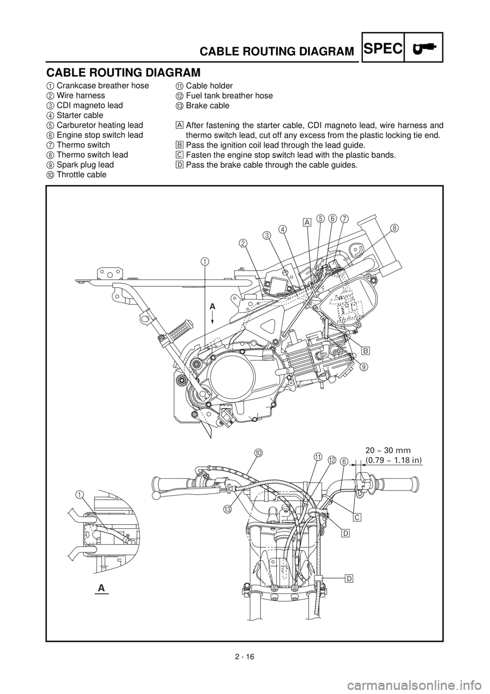
SPECCABLE ROUTING DIAGRAM
CABLE ROUTING DIAGRAM
1Crankcase breather hose
2Wire harness
3CDI magneto lead
4Starter cable
5Carburetor heating lead
6Engine stop switch lead
7Thermo switch
8Thermo switch lead
9Spark plug lead
0Throttle cableACable holder
BFuel tank breather hose
CBrake cable
After fastening the starter cable, CDI magneto lead, wire harness and
thermo switch lead, cut off any excess from the plastic locking tie end.
õPass the ignition coil lead through the lead guide.
‚Fasten the engine stop switch lead with the plastic bands.
ëPass the brake cable through the cable guides.
12345
9
0
B A
6
C 1
õ
‚
ë
ë
A
A
67
8
20 ~ 30 mm
(0.79 ~ 1.18 in)
Page 104 of 288
2 - 17
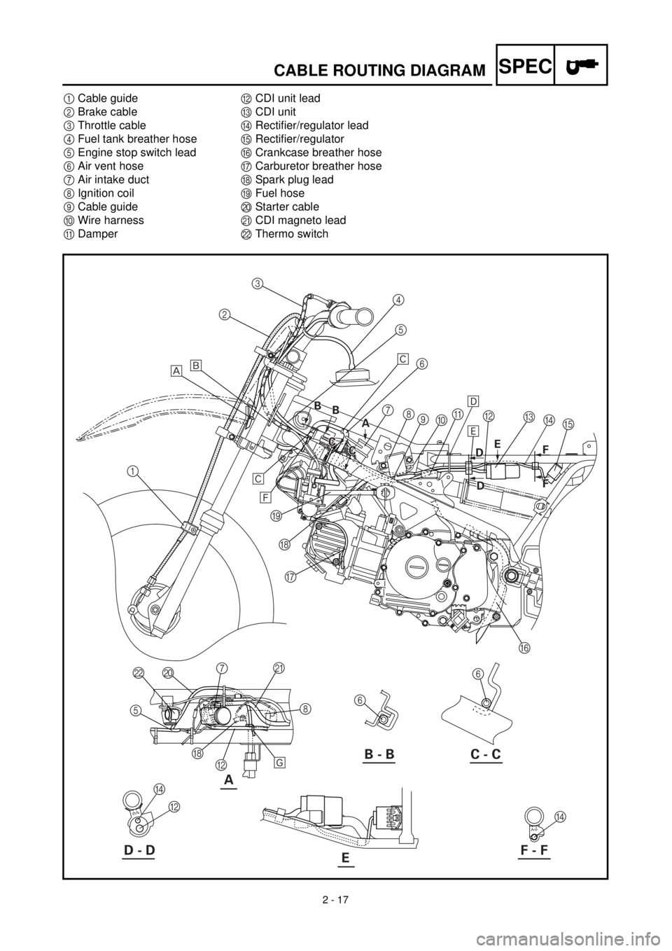
SPECCABLE ROUTING DIAGRAM
1Cable guide
2Brake cable
3Throttle cable
4Fuel tank breather hose
5Engine stop switch lead
6Air vent hose
7Air intake duct
8Ignition coil
9Cable guide
0Wire harness
ADamperBCDI unit lead
CCDI unit
DRectifier/regulator lead
ERectifier/regulator
FCrankcase breather hose
GCarburetor breather hose
HSpark plug lead
IFuel hose
JStarter cable
KCDI magneto lead
LThermo switch
A
123
4
5
6
7
8
9
0A
C
E B
F G H I
6
6 J L
5
H
B8 K
7 ‚
ä
‚
ì
í
B - B C - C
D - DF - FE
õ
ë
D
D
B
D
A A B
B B
B
C
C C
CE
B D
B
D
F F F F
Page 106 of 288
2 - 18
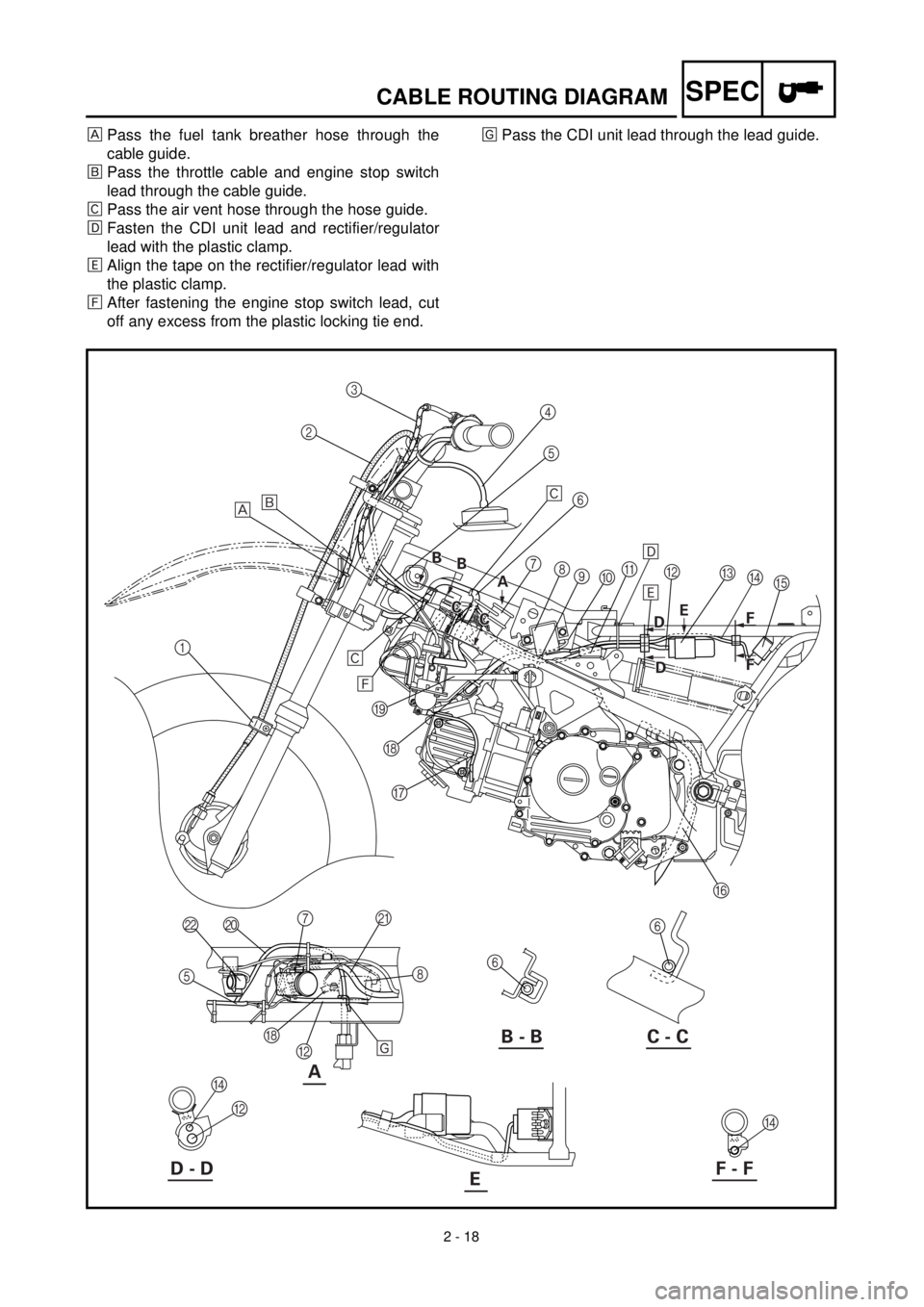
SPECCABLE ROUTING DIAGRAM
Pass the fuel tank breather hose through the
cable guide.
õPass the throttle cable and engine stop switch
lead through the cable guide.
‚Pass the air vent hose through the hose guide.
ëFasten the CDI unit lead and rectifier/regulator
lead with the plastic clamp.
äAlign the tape on the rectifier/regulator lead with
the plastic clamp.
ìAfter fastening the engine stop switch lead, cut
off any excess from the plastic locking tie end.íPass the CDI unit lead through the lead guide.
A
123
4
5
6
7
8
9
0A
C
E B
F G H I
6
6 J L
5
H
B8 K
7 ‚
ä
‚
ì
í
B - B C - C
D - DF - FE
õ
ë
D
D
B
D
A A B
B B
B
C
C C
CE
B D
B
D
F F F F
Page 108 of 288
3 - 1
INSP
ADJMAINTENANCE INTERVALS/
PERIODIC MAINTENANCE AND LUBRICATION
EC300000
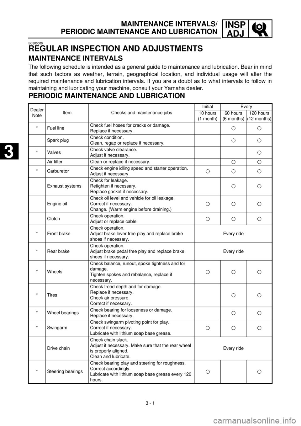
REGULAR INSPECTION AND ADJUSTMENTS
MAINTENANCE INTERVALS
The following schedule is intended as a general guide to maintenance and lubrication. Bear in mind
that such factors as weather, terrain, geographical location, and individual usage will alter the
required maintenance and lubrication intervals. If you are a doubt as to what intervals to follow in
maintaining and lubricating your machine, consult your Yamaha dealer.
PERIODIC MAINTENANCE AND LUBRICATION
Dealer
NoteItem Checks and maintenance jobsInitial Every
10 hours
(1 month)60 hours
(6 months)120 hours
(12 months)
* Fuel lineCheck fuel hoses for cracks or damage.
Replace if necessary.
Spark plugCheck condition.
Clean, regap or replace if necessary.
* ValvesCheck valve clearance.
Adjust if necessary.
Air filter Clean or replace if necessary.
* CarburetorCheck engine idling speed and starter operation.
Adjust if necessary.
Exhaust systemsCheck for leakage.
Retighten if necessary.
Replace gasket if necessary.
Engine oilCheck oil level and vehicle for oil leakage.
Correct if necessary.
Change. (Warm engine before draining.)
ClutchCheck operation.
Adjust or replace cable.
* Front brakeCheck operation.
Adjust brake lever free play and replace brake
shoes if necessary.Every ride
* Rear brakeCheck operation.
Adjust brake pedal free play and replace brake
shoes if necessary.Every ride
* WheelsCheck balance, runout, spoke tightness and for
damage.
Tighten spokes and rebalance, replace if
necessary.
* TiresCheck tread depth and for damage.
Replace if necessary.
Check air pressure.
Correct if necessary.
* Wheel bearingsCheck bearing for looseness or damage.
Replace if necessary.
* SwingarmCheck swingarm pivoting point for play.
Correct if necessary.
Lubricate with lithium soap base grease.
Drive chainCheck chain slack.
Adjust if necessary. Make sure that the rear wheel
is properly aligned.
Clean and lubricate.Every ride
* Steering bearingsCheck bearing play and steering for roughness.
Correct accordingly.
Lubricate with lithium soap base grease every 120
hours.
3
3
Page 148 of 288
4 - 1
ENG
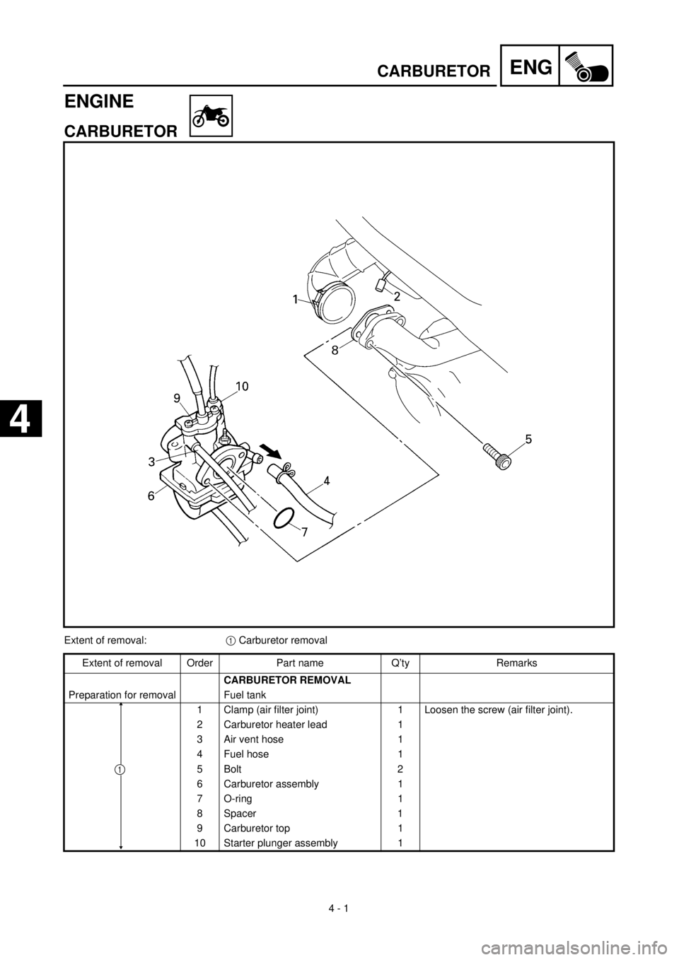
ENGINE
CARBURETOR
Extent of removal:1 Carburetor removal
Extent of removal Order Part name Q’ty Remarks
CARBURETOR REMOVAL
Preparation for removal Fuel tank
1 Clamp (air filter joint) 1 Loosen the screw (air filter joint).
2 Carburetor heater lead 1
3 Air vent hose 1
4 Fuel hose 1
5 Bolt 2
6 Carburetor assembly 1
7 O-ring 1
8 Spacer 1
9 Carburetor top 1
10 Starter plunger assembly 1
1
CARBURETOR
4
Page 158 of 288
4 - 6
ENGCARBURETOR
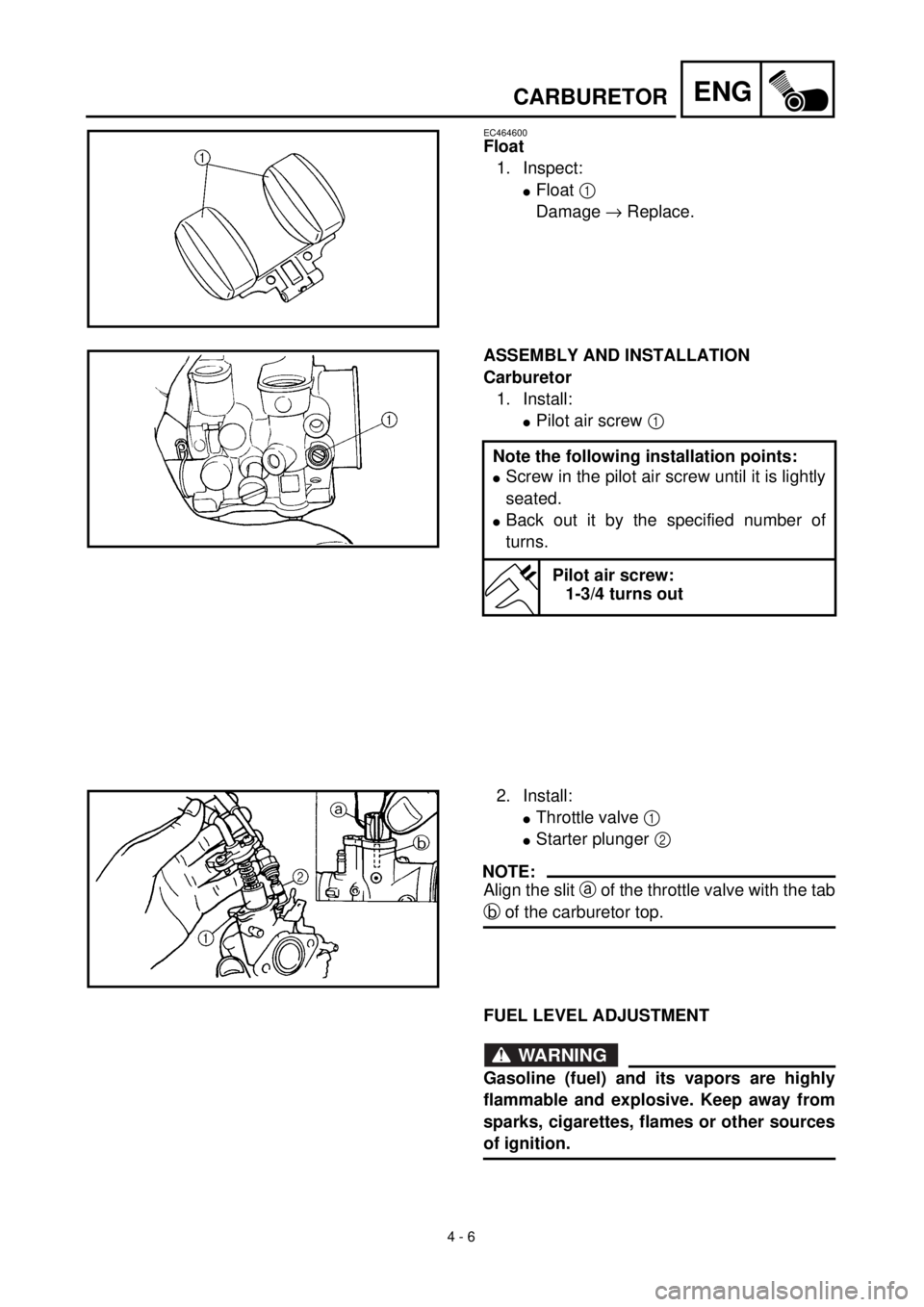
EC464600
Float
1. Inspect:
lFloat 1
Damage ® Replace.
ASSEMBLY AND INSTALLATION
Carburetor
1. Install:
lPilot air screw 1
Note the following installation points:
lScrew in the pilot air screw until it is lightly
seated.
lBack out it by the specified number of
turns.
Pilot air screw:
1-3/4 turns out
2. Install:
lThrottle valve 1
lStarter plunger 2
NOTE:
Align the slit a of the throttle valve with the tab
b of the carburetor top.
FUEL LEVEL ADJUSTMENT
WARNING
Gasoline (fuel) and its vapors are highly
flammable and explosive. Keep away from
sparks, cigarettes, flames or other sources
of ignition.
Page 160 of 288
4 - 7
ENGCARBURETOR
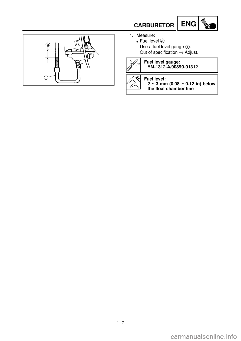
1. Measure:
lFuel level a
Use a fuel level gauge 1.
Out of specification ® Adjust.
Fuel level gauge:
YM-1312-A/90890-01312
Fuel level:
2 ~ 3 mm (0.08 ~ 0.12 in) below
the float chamber line
Page 162 of 288
4 - 8
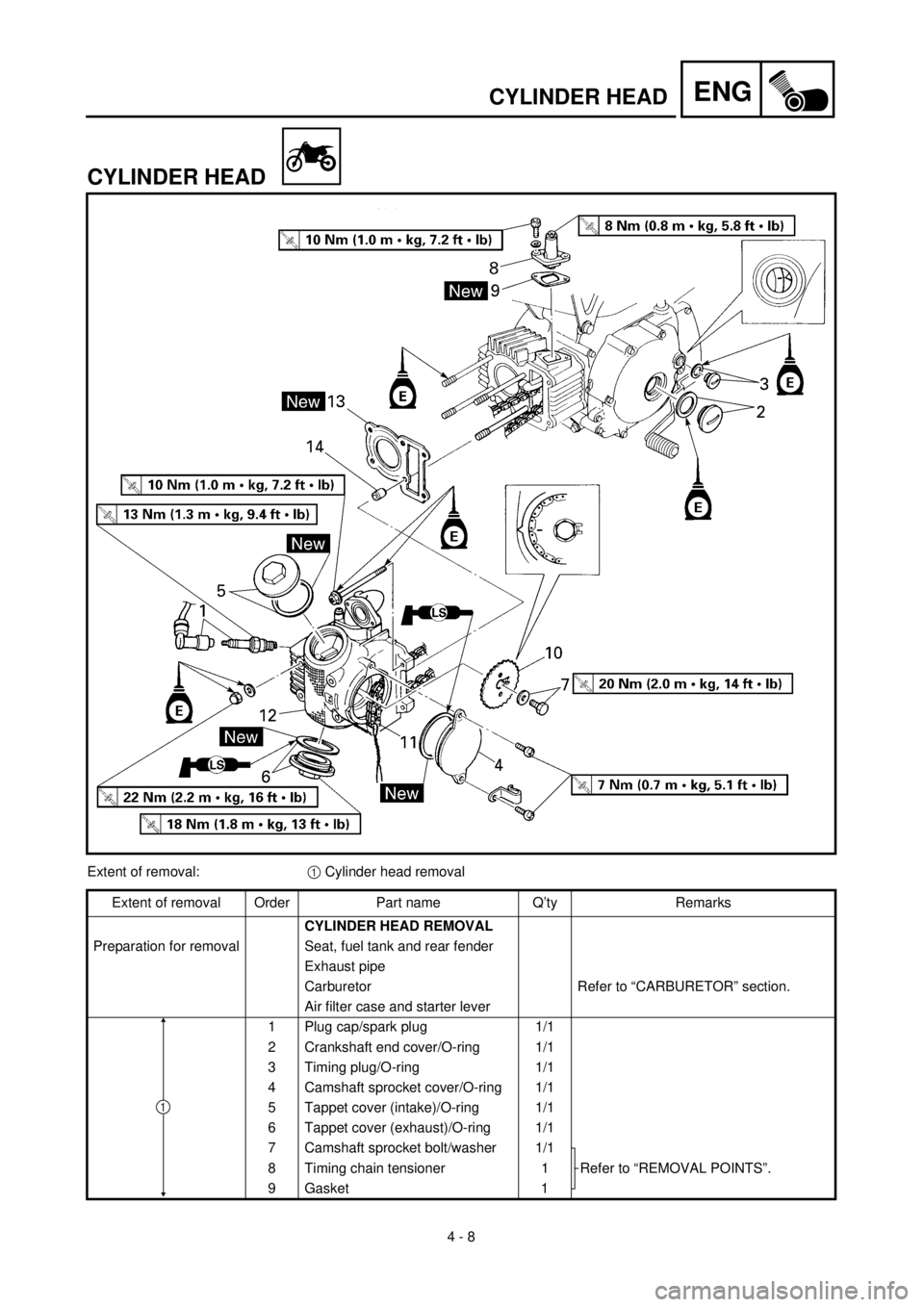
ENGCYLINDER HEAD
CYLINDER HEAD
Extent of removal:1 Cylinder head removal
Extent of removal Order Part name Q’ty Remarks
CYLINDER HEAD REMOVAL
Preparation for removal Seat, fuel tank and rear fender
Exhaust pipe
Carburetor Refer to “CARBURETOR” section.
Air filter case and starter lever
1 Plug cap/spark plug 1/1
2 Crankshaft end cover/O-ring 1/1
3 Timing plug/O-ring 1/1
4 Camshaft sprocket cover/O-ring 1/1
5 Tappet cover (intake)/O-ring 1/1
6 Tappet cover (exhaust)/O-ring 1/1
7 Camshaft sprocket bolt/washer 1/1
Refer to “REMOVAL POINTS”. 8 Timing chain tensioner 1
9 Gasket 1
1