Chain cover YAMAHA TTR90 2002 Owners Manual
[x] Cancel search | Manufacturer: YAMAHA, Model Year: 2002, Model line: TTR90, Model: YAMAHA TTR90 2002Pages: 288, PDF Size: 15.07 MB
Page 65 of 288

SPEC
2 - 10
Part to be tightened Thread size Q’tyTightening torque
Nm m•kg ft•lb
Cylinder head nut M8 ´ 1.25 4 22 2.2 16
Cylinder head bolt M6 ´ 1.0 2 10 1.0 7.2
Spark plug M10 ´ 1.0 1 13 1.3 9.4
Camshaft sprocket cover bolt M6 ´ 1.0 2 7 0.7 5.1
Tappet cover M45 ´ 1.5 2 18 1.8 13
Exhaust pipe stud bolt M6 ´ 1.0 2 7 0.7 5.1
Rotor nut M12 ´ 1.25 1 48 4.8 35
Timing chain guide (rear) M6 ´ 1.0 2 10 1.0 7.2
Valve clearance adjust screw locknut M5 ´ 0.5 2 7 0.7 5.1
Camshaft sprocket M8 ´ 1.25 1 20 2.0 14
Camshaft bearing retainer M6 ´ 1.0 1 10 1.0 7.2
Timing chain tensioner cap bolt M8 ´ 1.25 1 8 0.8 5.8
Timing chain tensioner M6 ´ 1.0 2 10 1.0 7.2
Oil pump M6 ´ 1.0 2 7 0.7 5.1
Drain bolt M12 ´ 1.5 1 20 2.0 14
Carburetor joint (cylinder head side) M6 ´ 1.0 2 7 0.7 5.1
Carburetor joint (carburetor side) M6 ´ 1.0 2 7 0.7 5.1
Air filter case M6 ´ 1.0 2 7 0.7 5.1
Exhaust pipe M6 ´ 1.0 2 7 0.7 5.1
Exhaust pipe protector M6 ´ 1.0 7 7 0.7 5.1
Silencer M8 ´ 1.25 1 24 2.4 17
Silencer protector M5 ´ 0.8 2 4 0.4 2.9
Crankcase M6 ´ 1.0 9 10 1.0 7.2
Crankcase cover (left) M6 ´ 1.0 8 7 0.7 5.1
Drive sprocket cover M6 ´ 1.0 2 7 0.7 5.1
Crankcase cover (right) M6 ´ 1.0 9 7 0.7 5.1
Timing plug M14 ´ 1.5 1 7 0.7 5.1
Crankshaft end cover M32 ´ 1.5 1 7 0.7 5.1
Cylinder head stud bolt M8 ´ 1.25 4 13 1.3 9.4
Kick crank M6 ´ 1.0 1 10 1.0 7.2
Primary drive gear M12 ´ 1.0 1 50 5.0 36
Pressure plate M5 ´ 0.8 4 6 0.6 4.3
Clutch boss M14 ´ 1.0 1 70 7.0 50
Main axle bearing retainer M6 ´ 1.0 1 10 1.0 7.2
Shift pedal M6 ´ 1.0 1 8 0.8 5.8
Clutch adjust screw locknut M6 ´ 1.0 1 8 0.8 5.8
Pickup coil M6 ´ 1.0 2 10 1.0 7.2
Stator assembly M6 ´ 1.0 3 10 1.0 7.2
MAINTENANCE SPECIFICATIONS
Page 162 of 288
4 - 8
ENGCYLINDER HEAD
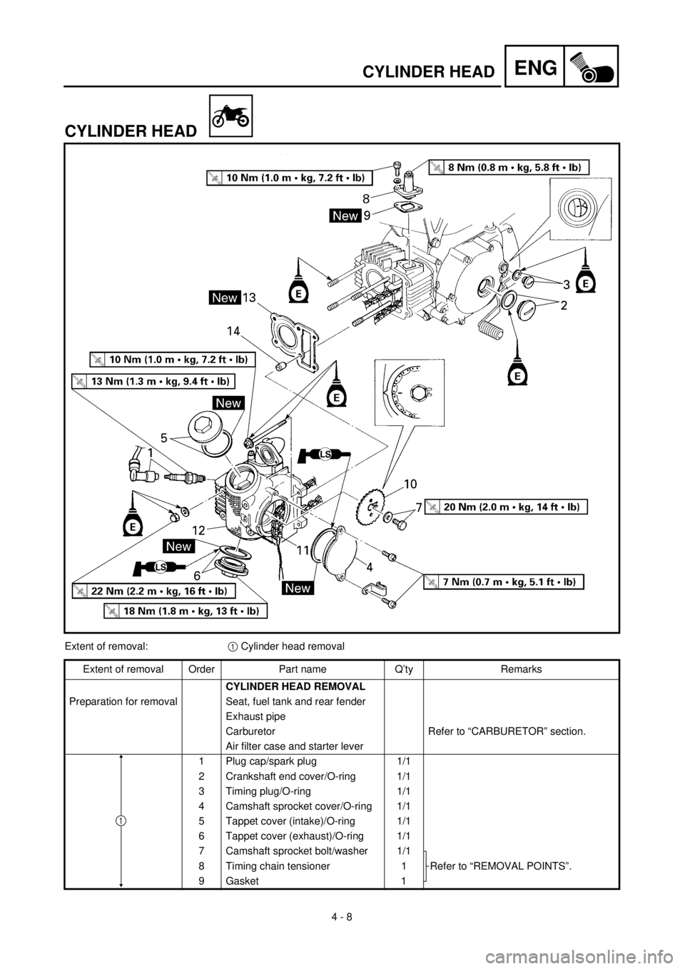
CYLINDER HEAD
Extent of removal:1 Cylinder head removal
Extent of removal Order Part name Q’ty Remarks
CYLINDER HEAD REMOVAL
Preparation for removal Seat, fuel tank and rear fender
Exhaust pipe
Carburetor Refer to “CARBURETOR” section.
Air filter case and starter lever
1 Plug cap/spark plug 1/1
2 Crankshaft end cover/O-ring 1/1
3 Timing plug/O-ring 1/1
4 Camshaft sprocket cover/O-ring 1/1
5 Tappet cover (intake)/O-ring 1/1
6 Tappet cover (exhaust)/O-ring 1/1
7 Camshaft sprocket bolt/washer 1/1
Refer to “REMOVAL POINTS”. 8 Timing chain tensioner 1
9 Gasket 1
1
Page 166 of 288
4 - 10
ENGCYLINDER HEAD
REMOVAL POINTS
Cylinder head
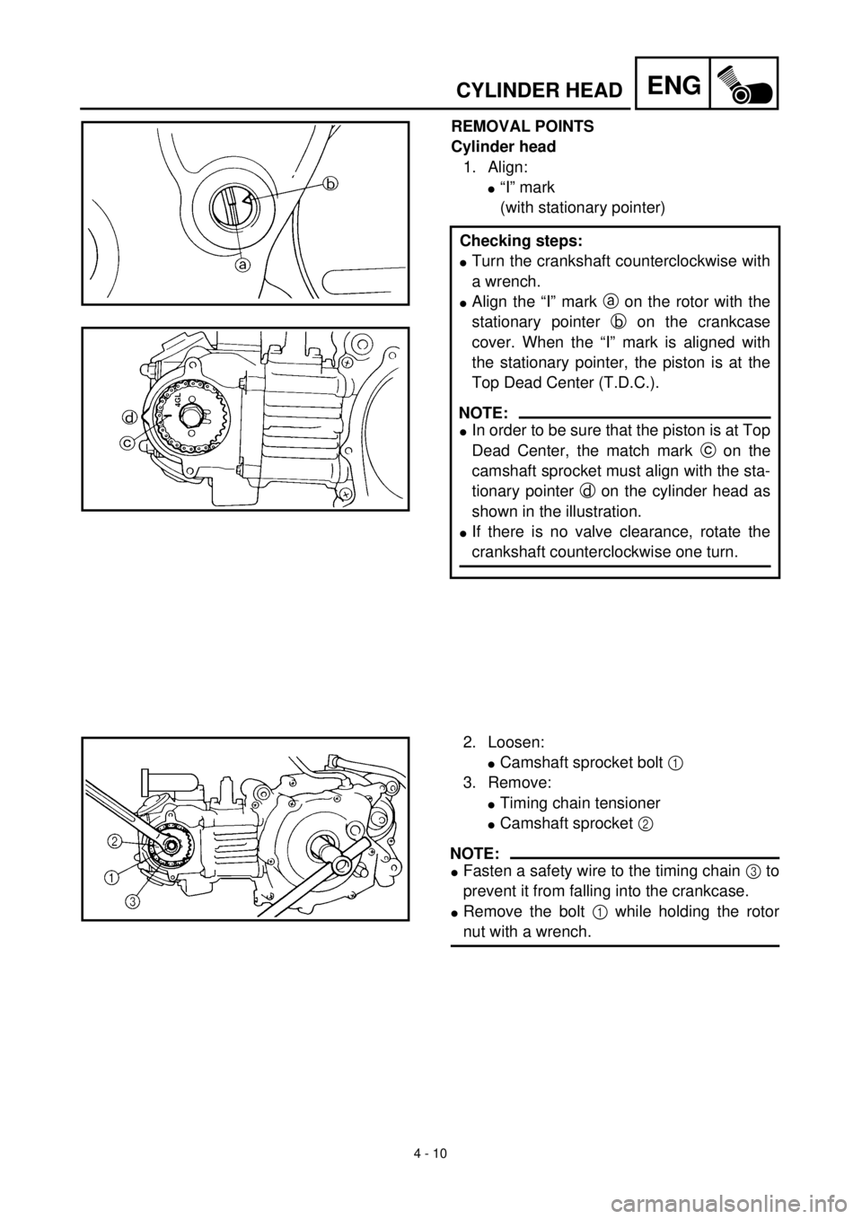
1. Align:
l“I” mark
(with stationary pointer)
Checking steps:
lTurn the crankshaft counterclockwise with
a wrench.
lAlign the “I” mark a on the rotor with the
stationary pointer b on the crankcase
cover. When the “I” mark is aligned with
the stationary pointer, the piston is at the
Top Dead Center (T.D.C.).
NOTE:
lIn order to be sure that the piston is at Top
Dead Center, the match mark c on the
camshaft sprocket must align with the sta-
tionary pointer d on the cylinder head as
shown in the illustration.
lIf there is no valve clearance, rotate the
crankshaft counterclockwise one turn.
2. Loosen:
lCamshaft sprocket bolt 1
3. Remove:
lTiming chain tensioner
lCamshaft sprocket 2
NOTE:
lFasten a safety wire to the timing chain 3 to
prevent it from falling into the crankcase.
lRemove the bolt 1 while holding the rotor
nut with a wrench.
Page 168 of 288
4 - 11
ENGCYLINDER HEAD
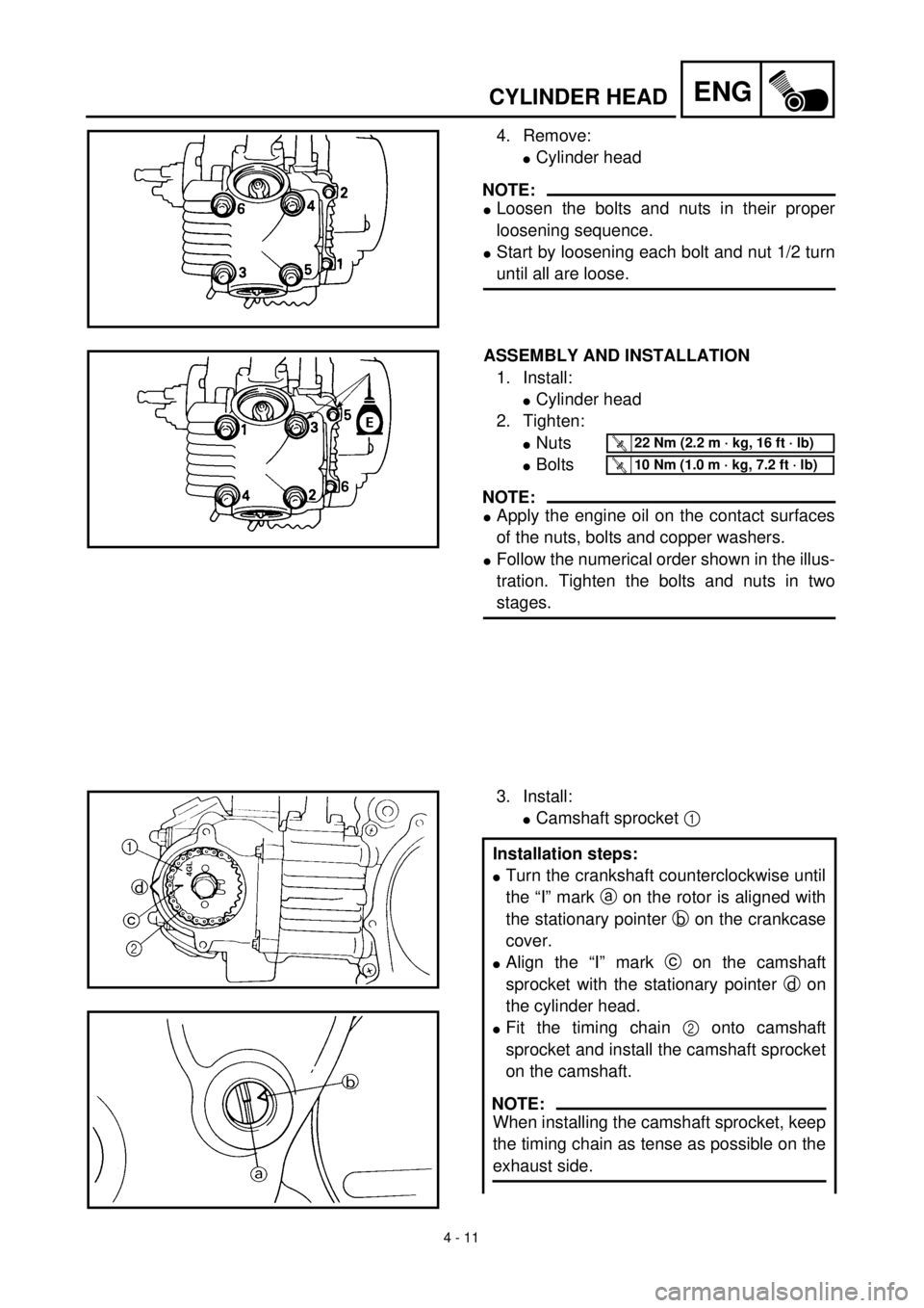
4. Remove:
lCylinder head
NOTE:
lLoosen the bolts and nuts in their proper
loosening sequence.
lStart by loosening each bolt and nut 1/2 turn
until all are loose.
ASSEMBLY AND INSTALLATION
1. Install:
lCylinder head
2. Tighten:
lNuts
lBolts
NOTE:
lApply the engine oil on the contact surfaces
of the nuts, bolts and copper washers.
lFollow the numerical order shown in the illus-
tration. Tighten the bolts and nuts in two
stages.
T R..22 Nm (2.2 m · kg, 16 ft · lb)
T R..10 Nm (1.0 m · kg, 7.2 ft · lb)
3. Install:
lCamshaft sprocket 1
Installation steps:
lTurn the crankshaft counterclockwise until
the “I” mark a on the rotor is aligned with
the stationary pointer b on the crankcase
cover.
lAlign the “I” mark c on the camshaft
sprocket with the stationary pointer d on
the cylinder head.
lFit the timing chain 2 onto camshaft
sprocket and install the camshaft sprocket
on the camshaft.
NOTE:
When installing the camshaft sprocket, keep
the timing chain as tense as possible on the
exhaust side.
Page 198 of 288
4 - 26
ENGCYLINDER AND PISTON
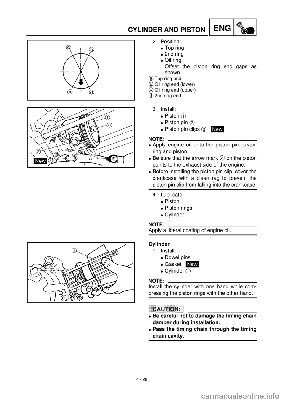
2. Position:
lTop ring
l2nd ring
lOil ring
Offset the piston ring end gaps as
shown.
aTop ring end
bOil ring end (lower)
cOil ring end (upper)
d2nd ring end
3. Install:
lPiston 1
lPiston pin 2
lPiston pin clips 3
NOTE:
lApply engine oil onto the piston pin, piston
ring and piston.
lBe sure that the arrow mark a on the piston
points to the exhaust side of the engine.
lBefore installing the piston pin clip, cover the
crankcase with a clean rag to prevent the
piston pin clip from falling into the crankcase.
4. Lubricate:
lPiston
lPiston rings
lCylinder
NOTE:
Apply a liberal coating of engine oil.
New
Cylinder
1. Install:
lDowel pins
lGasket
lCylinder 1
NOTE:
Install the cylinder with one hand while com-
pressing the piston rings with the other hand.
CAUTION:
lBe careful not to damage the timing chain
damper during installation.
lPass the timing chain through the timing
chain cavity.
New