oil YAMAHA TTR90 2005 Betriebsanleitungen (in German)
[x] Cancel search | Manufacturer: YAMAHA, Model Year: 2005, Model line: TTR90, Model: YAMAHA TTR90 2005Pages: 364, PDF-Größe: 10.2 MB
Page 64 of 364
SPEC
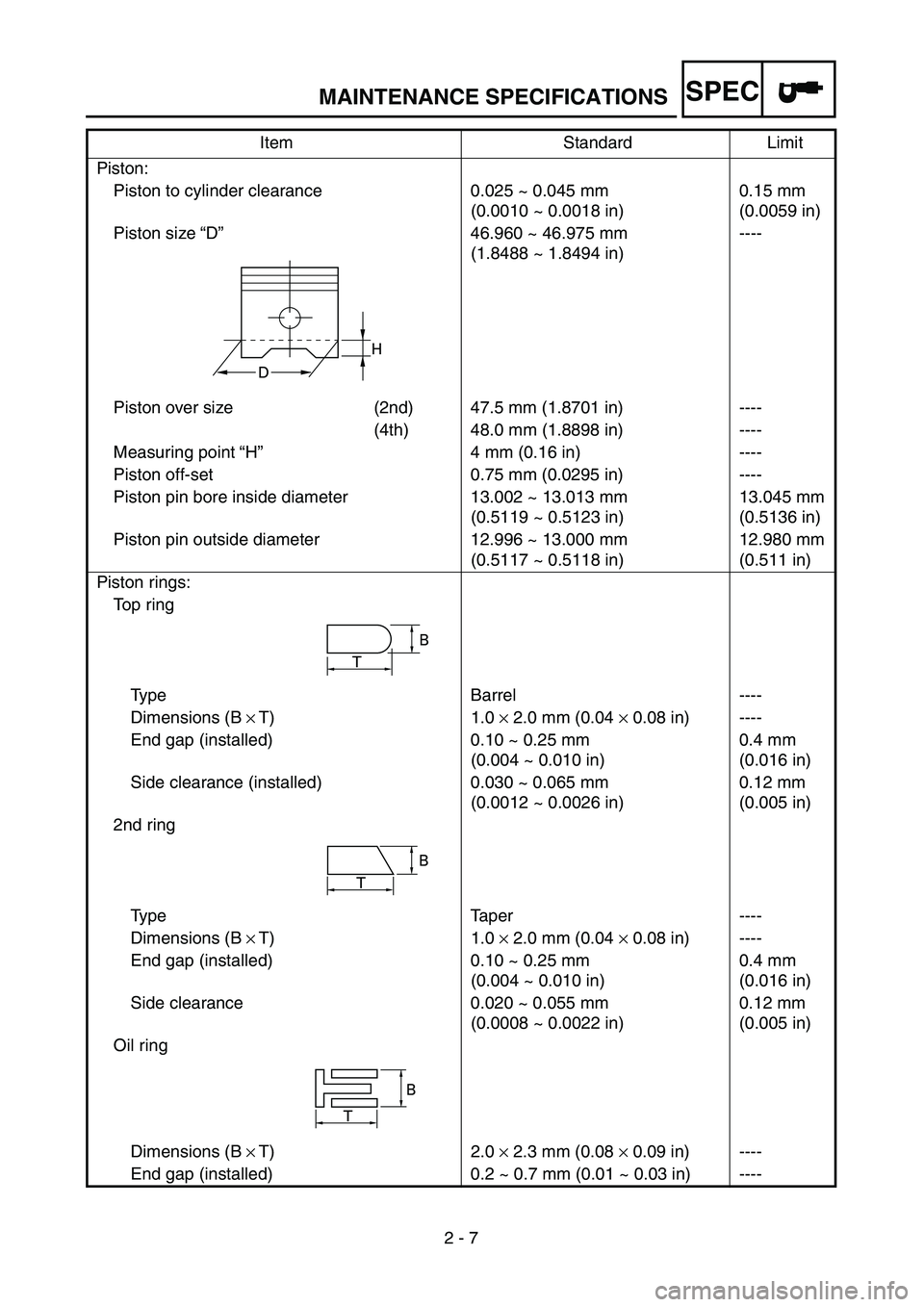
2 - 7 Piston:
Piston to cylinder clearance 0.025 ~ 0.045 mm
(0.0010 ~ 0.0018 in)0.15 mm
(0.0059 in)
Piston size “D”46.960 ~ 46.975 mm
(1.8488 ~ 1.8494 in)----
Piston over size (2nd) 47.5 mm (1.8701 in) ----
(4th) 48.0 mm (1.8898 in) ----
Measuring point “H”4 mm (0.16 in) ----
Piston off-set 0.75 mm (0.0295 in) ----
Piston pin bore inside diameter 13.002 ~ 13.013 mm
(0.5119 ~ 0.5123 in)13.045 mm
(0.5136 in)
Piston pin outside diameter 12.996 ~ 13.000 mm
(0.5117 ~ 0.5118 in)12.980 mm
(0.511 in)
Piston rings:
Top ring
Type Barrel ----
Dimensions (B × T) 1.0 × 2.0 mm (0.04 × 0.08 in) ----
End gap (installed) 0.10 ~ 0.25 mm
(0.004 ~ 0.010 in)0.4 mm
(0.016 in)
Side clearance (installed) 0.030 ~ 0.065 mm
(0.0012 ~ 0.0026 in)0.12 mm
(0.005 in)
2nd ring
Type Taper ----
Dimensions (B × T) 1.0 × 2.0 mm (0.04 × 0.08 in) ----
End gap (installed) 0.10 ~ 0.25 mm
(0.004 ~ 0.010 in)0.4 mm
(0.016 in)
Side clearance 0.020 ~ 0.055 mm
(0.0008 ~ 0.0022 in)0.12 mm
(0.005 in)
Oil ring
Dimensions (B × T) 2.0 × 2.3 mm (0.08 × 0.09 in) ----
End gap (installed) 0.2 ~ 0.7 mm (0.01 ~ 0.03 in) ----Item Standard Limit
H
D
T
B
B
T
B
T
MAINTENANCE SPECIFICATIONS
Page 66 of 364
SPEC
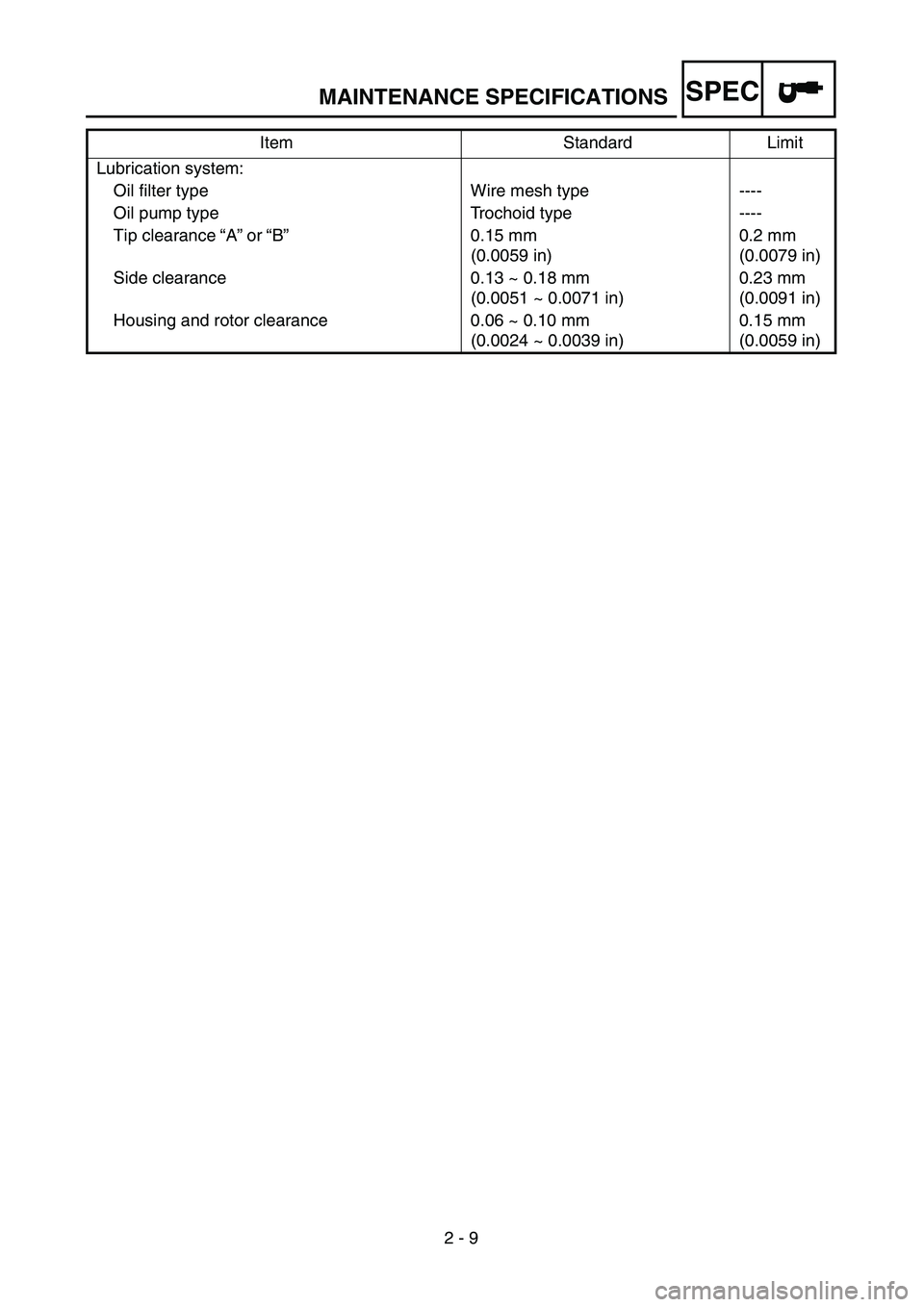
2 - 9 Lubrication system:
Oil filter type Wire mesh type ----
Oil pump type Trochoid type ----
Tip clearance “A” or “B”0.15 mm
(0.0059 in)0.2 mm
(0.0079 in)
Side clearance 0.13 ~ 0.18 mm
(0.0051 ~ 0.0071 in)0.23 mm
(0.0091 in)
Housing and rotor clearance 0.06 ~ 0.10 mm
(0.0024 ~ 0.0039 in)0.15 mm
(0.0059 in) Item Standard Limit
MAINTENANCE SPECIFICATIONS
Page 67 of 364
SPEC
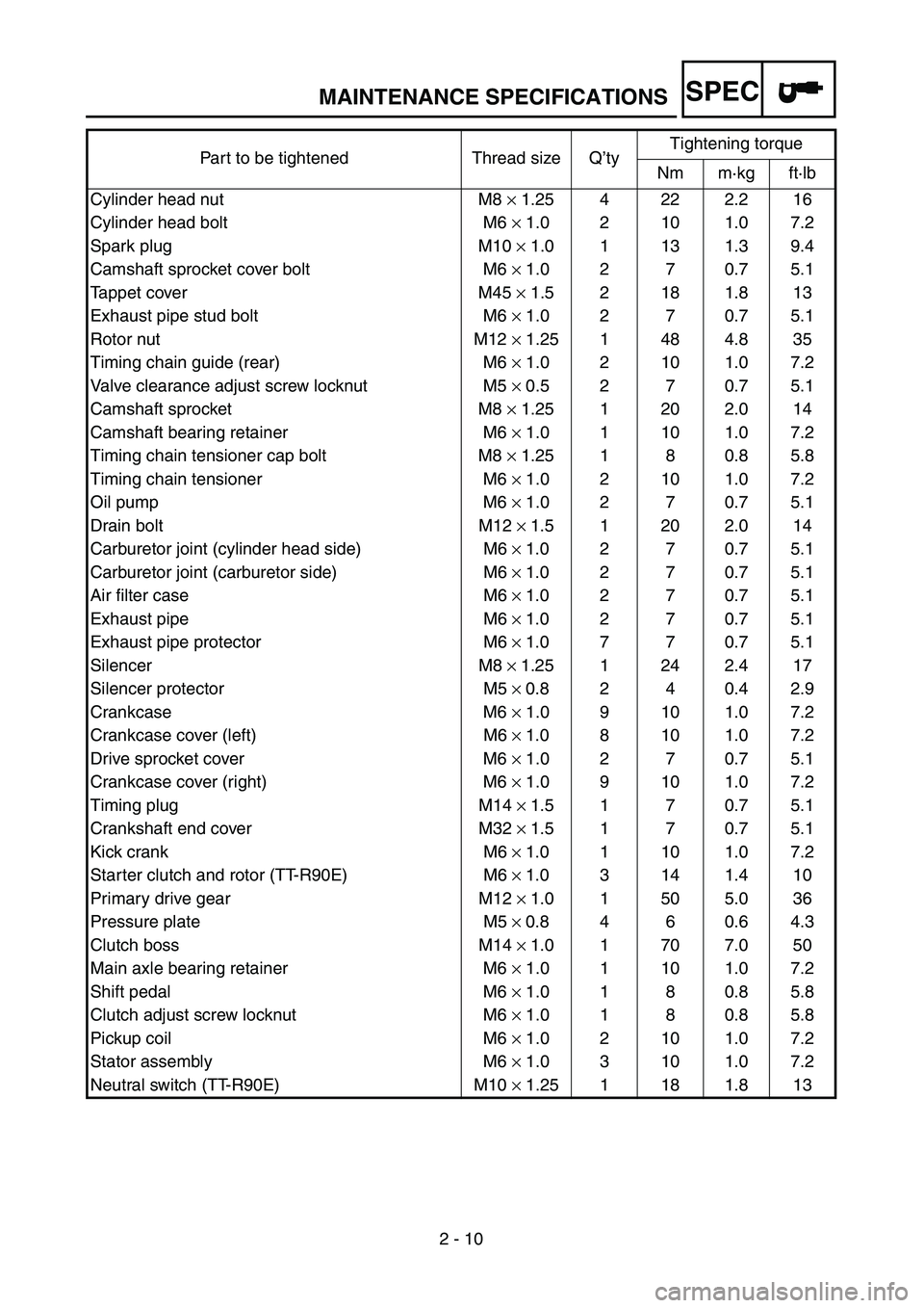
2 - 10 Part to be tightened Thread size Q’tyTightening torque
Nm m·kg ft·lb
Cylinder head nut M8 × 1.25 4 22 2.2 16
Cylinder head bolt M6 × 1.0 2 10 1.0 7.2
Spark plug M10 × 1.0 1 13 1.3 9.4
Camshaft sprocket cover bolt M6 × 1.0 2 7 0.7 5.1
Tappet cover M45 × 1.5 2 18 1.8 13
Exhaust pipe stud bolt M6 × 1.0 2 7 0.7 5.1
Rotor nut M12 × 1.25 1 48 4.8 35
Timing chain guide (rear) M6 × 1.0 2 10 1.0 7.2
Valve clearance adjust screw locknut M5 × 0.5 2 7 0.7 5.1
Camshaft sprocket M8 × 1.25 1 20 2.0 14
Camshaft bearing retainer M6 × 1.0 1 10 1.0 7.2
Timing chain tensioner cap bolt M8 × 1.25 1 8 0.8 5.8
Timing chain tensioner M6 × 1.0 2 10 1.0 7.2
Oil pump M6 × 1.0 2 7 0.7 5.1
Drain bolt M12 × 1.5 1 20 2.0 14
Carburetor joint (cylinder head side) M6 × 1.0 2 7 0.7 5.1
Carburetor joint (carburetor side) M6 × 1.0 2 7 0.7 5.1
Air filter case M6 × 1.0 2 7 0.7 5.1
Exhaust pipe M6 × 1.0 2 7 0.7 5.1
Exhaust pipe protector M6 × 1.0 7 7 0.7 5.1
Silencer M8 × 1.25 1 24 2.4 17
Silencer protector M5 × 0.8 2 4 0.4 2.9
Crankcase M6 × 1.0 9 10 1.0 7.2
Crankcase cover (left) M6 × 1.0 8 10 1.0 7.2
Drive sprocket cover M6 × 1.0 2 7 0.7 5.1
Crankcase cover (right) M6 × 1.0 9 10 1.0 7.2
Timing plug M14 × 1.5 1 7 0.7 5.1
Crankshaft end cover M32 × 1.5 1 7 0.7 5.1
Kick crank M6 × 1.0 1 10 1.0 7.2
Starter clutch and rotor (TT-R90E) M6 × 1.0 3 14 1.4 10
Primary drive gear M12 × 1.0 1 50 5.0 36
Pressure plate M5 × 0.8 4 6 0.6 4.3
Clutch boss M14 × 1.0 1 70 7.0 50
Main axle bearing retainer M6 × 1.0 1 10 1.0 7.2
Shift pedal M6 × 1.0 1 8 0.8 5.8
Clutch adjust screw locknut M6 × 1.0 1 8 0.8 5.8
Pickup coil M6 × 1.0 2 10 1.0 7.2
Stator assembly M6 × 1.0 3 10 1.0 7.2
Neutral switch (TT-R90E) M10 × 1.25 1 18 1.8 13
MAINTENANCE SPECIFICATIONS
Page 68 of 364
SPEC
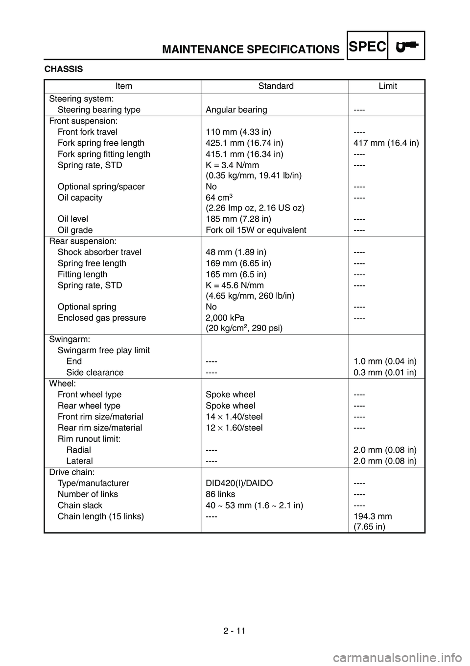
2 - 11 CHASSIS
Item Standard Limit
Steering system:
Steering bearing type Angular bearing ----
Front suspension:
Front fork travel 110 mm (4.33 in) ----
Fork spring free length 425.1 mm (16.74 in) 417 mm (16.4 in)
Fork spring fitting length 415.1 mm (16.34 in) ----
Spring rate, STD K = 3.4 N/mm
(0.35 kg/mm, 19.41 lb/in)----
Optional spring/spacer No ----
Oil capacity 64 cm
3
(2.26 Imp oz, 2.16 US oz) ----
Oil level 185 mm (7.28 in) ----
Oil grade Fork oil 15W or equivalent ----
Rear suspension:
Shock absorber travel 48 mm (1.89 in) ----
Spring free length 169 mm (6.65 in) ----
Fitting length 165 mm (6.5 in) ----
Spring rate, STD K = 45.6 N/mm
(4.65 kg/mm, 260 lb/in)----
Optional spring No ----
Enclosed gas pressure 2,000 kPa
(20 kg/cm
2, 290 psi)----
Swingarm:
Swingarm free play limit
End ---- 1.0 mm (0.04 in)
Side clearance ---- 0.3 mm (0.01 in)
Wheel:
Front wheel type Spoke wheel ----
Rear wheel type Spoke wheel ----
Front rim size/material 14 × 1.40/steel ----
Rear rim size/material 12 × 1.60/steel ----
Rim runout limit:
Radial ---- 2.0 mm (0.08 in)
Lateral ---- 2.0 mm (0.08 in)
Drive chain:
Type/manufacturer DID420(I)/DAIDO ----
Number of links 86 links ----
Chain slack 40 ~ 53 mm (1.6 ~ 2.1 in) ----
Chain length (15 links) ---- 194.3 mm
(7.65 in)
MAINTENANCE SPECIFICATIONS
Page 71 of 364
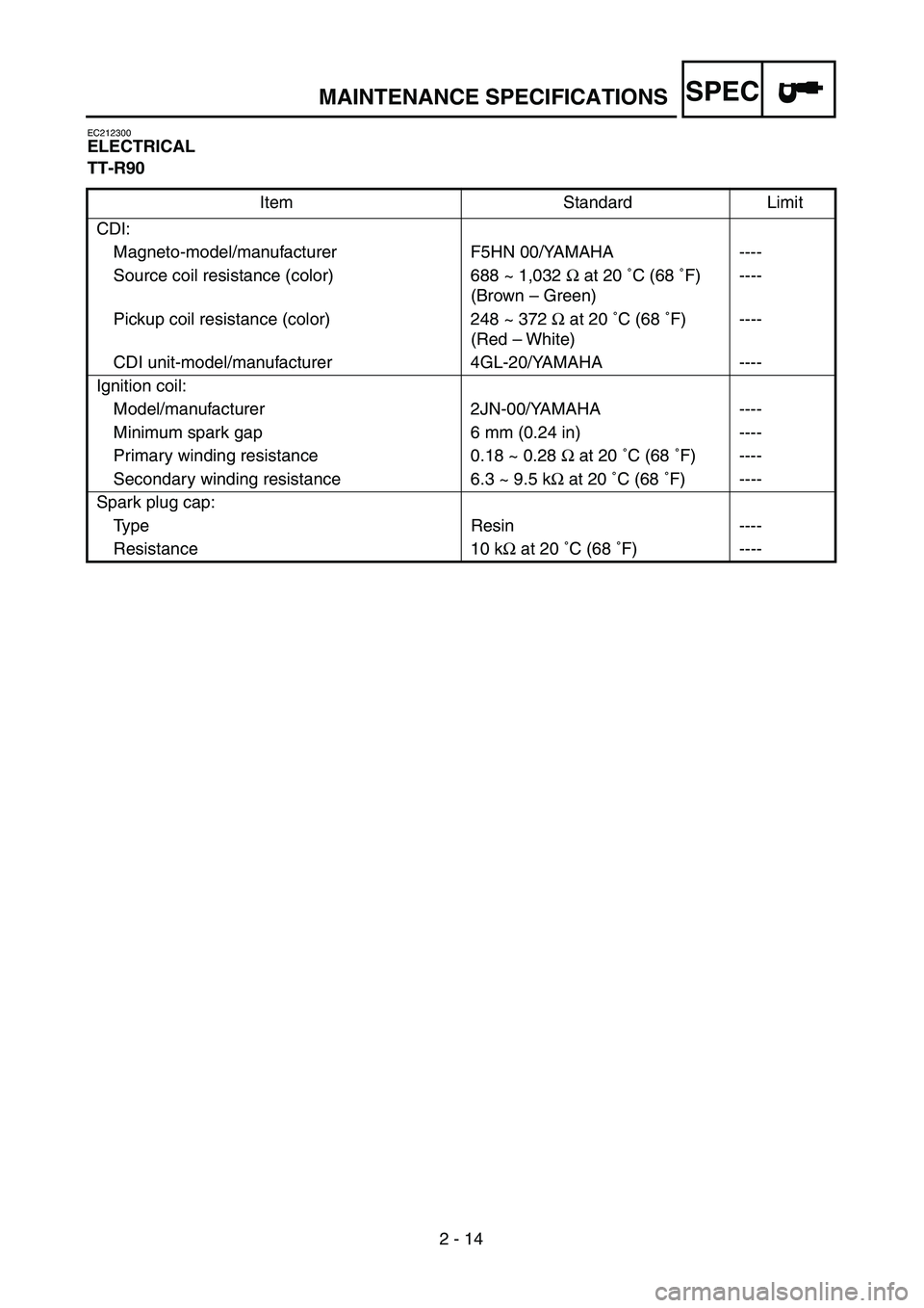
SPEC
2 - 14
EC212300
ELECTRICAL
TT-R90
Item Standard Limit
CDI:
Magneto-model/manufacturer F5HN 00/YAMAHA ----
Source coil resistance (color) 688 ~ 1,032 Ω at 20 ˚C (68 ˚F)
(Brown – Green)----
Pickup coil resistance (color) 248 ~ 372 Ω at 20 ˚C (68 ˚F)
(Red – White)----
CDI unit-model/manufacturer 4GL-20/YAMAHA ----
Ignition coil:
Model/manufacturer 2JN-00/YAMAHA ----
Minimum spark gap 6 mm (0.24 in) ----
Primary winding resistance 0.18 ~ 0.28 Ω at 20 ˚C (68 ˚F) ----
Secondary winding resistance 6.3 ~ 9.5 kΩ at 20 ˚C (68 ˚F) ----
Spark plug cap:
Type Resin ----
Resistance 10 kΩ at 20 ˚C (68 ˚F) ----
MAINTENANCE SPECIFICATIONS
Page 72 of 364
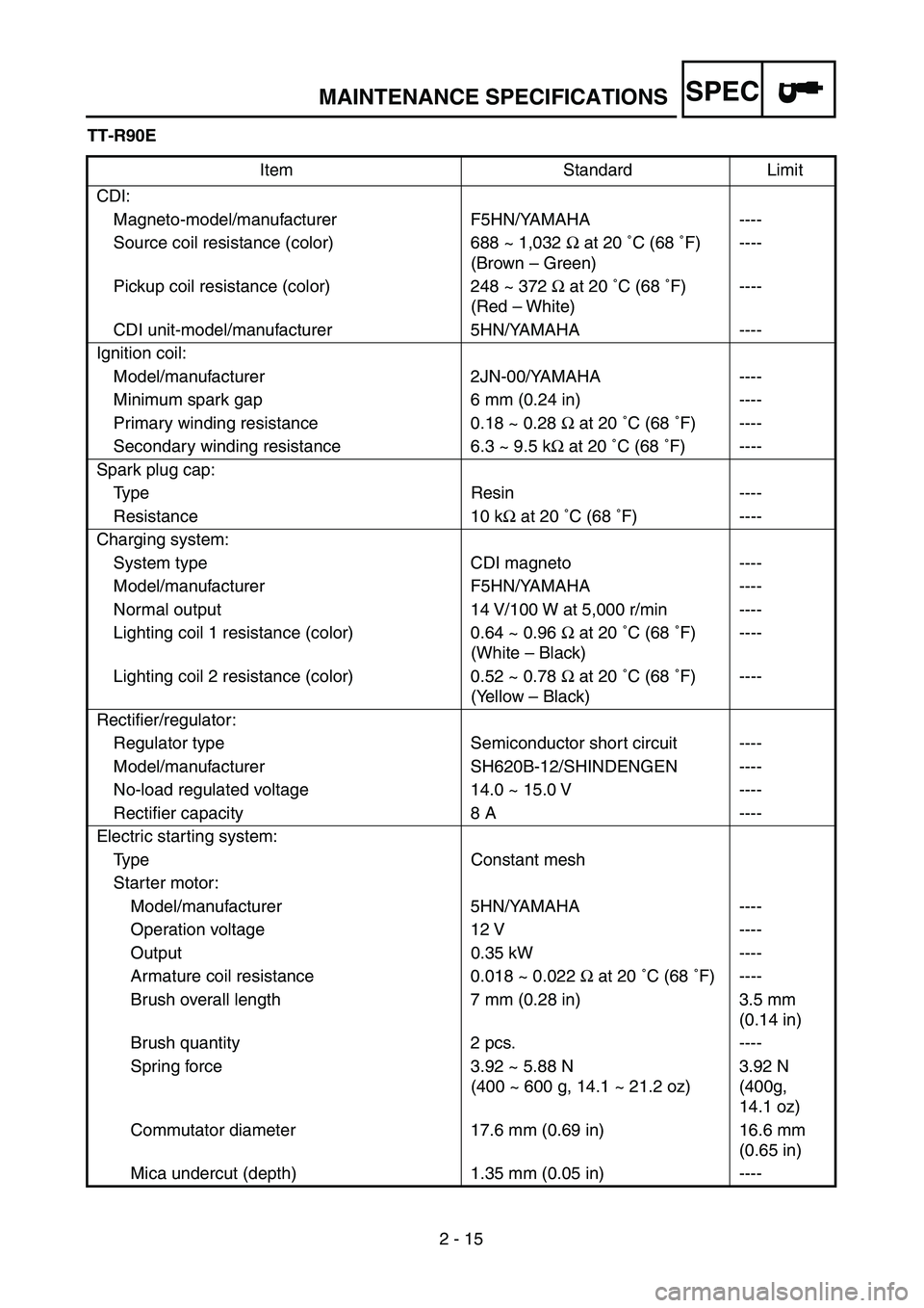
SPEC
2 - 15 TT-R90E
Item Standard Limit
CDI:
Magneto-model/manufacturer F5HN/YAMAHA ----
Source coil resistance (color) 688 ~ 1,032 Ω at 20 ˚C (68 ˚F)
(Brown – Green)----
Pickup coil resistance (color) 248 ~ 372 Ω at 20 ˚C (68 ˚F)
(Red – White)----
CDI unit-model/manufacturer 5HN/YAMAHA ----
Ignition coil:
Model/manufacturer 2JN-00/YAMAHA ----
Minimum spark gap 6 mm (0.24 in) ----
Primary winding resistance 0.18 ~ 0.28 Ω at 20 ˚C (68 ˚F) ----
Secondary winding resistance 6.3 ~ 9.5 kΩ at 20 ˚C (68 ˚F) ----
Spark plug cap:
Type Resin ----
Resistance 10 kΩ at 20 ˚C (68 ˚F) ----
Charging system:
System type CDI magneto ----
Model/manufacturer F5HN/YAMAHA ----
Normal output 14 V/100 W at 5,000 r/min ----
Lighting coil 1 resistance (color) 0.64 ~ 0.96 Ω at 20 ˚C (68 ˚F)
(White – Black)----
Lighting coil 2 resistance (color) 0.52 ~ 0.78 Ω at 20 ˚C (68 ˚F)
(Yellow – Black)----
Rectifier/regulator:
Regulator type Semiconductor short circuit ----
Model/manufacturer SH620B-12/SHINDENGEN ----
No-load regulated voltage 14.0 ~ 15.0 V ----
Rectifier capacity 8 A ----
Electric starting system:
Type Constant mesh
Starter motor:
Model/manufacturer 5HN/YAMAHA ----
Operation voltage 12 V ----
Output 0.35 kW ----
Armature coil resistance 0.018 ~ 0.022 Ω at 20 ˚C (68 ˚F) ----
Brush overall length 7 mm (0.28 in) 3.5 mm
(0.14 in)
Brush quantity 2 pcs. ----
Spring force 3.92 ~ 5.88 N
(400 ~ 600 g, 14.1 ~ 21.2 oz)3.92 N
(400g,
14.1 oz)
Commutator diameter 17.6 mm (0.69 in) 16.6 mm
(0.65 in)
Mica undercut (depth) 1.35 mm (0.05 in) ----
MAINTENANCE SPECIFICATIONS
Page 73 of 364
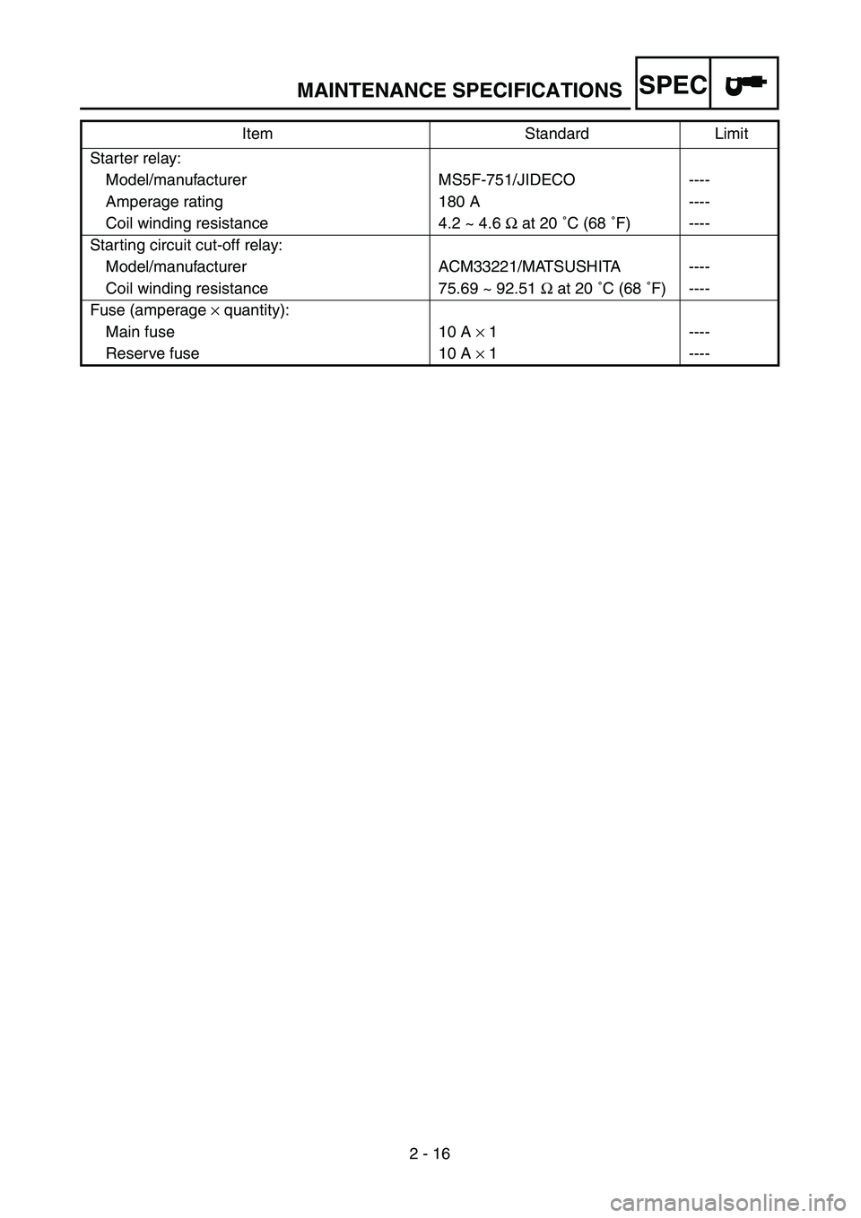
SPEC
2 - 16 Starter relay:
Model/manufacturer MS5F-751/JIDECO ----
Amperage rating 180 A ----
Coil winding resistance 4.2 ~ 4.6 Ω at 20 ˚C (68 ˚F) ----
Starting circuit cut-off relay:
Model/manufacturer ACM33221/MATSUSHITA ----
Coil winding resistance 75.69 ~ 92.51 Ω at 20 ˚C (68 ˚F) ----
Fuse (amperage × quantity):
Main fuse 10 A × 1 ----
Reserve fuse 10 A × 1 ---- Item Standard Limit
MAINTENANCE SPECIFICATIONS
Page 78 of 364
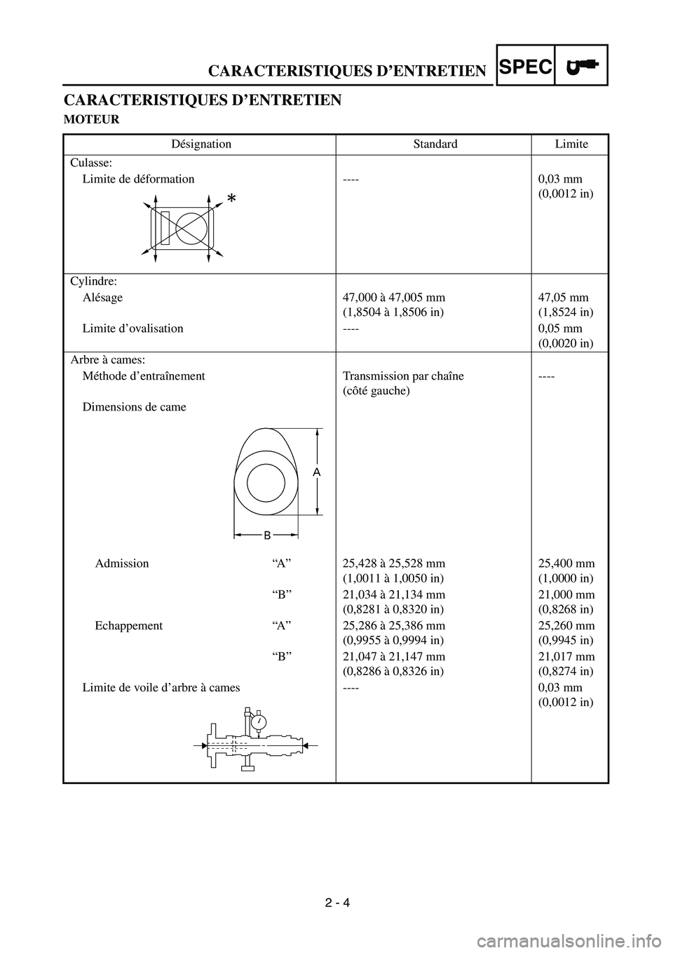
2 - 4
CARACTERISTIQUES D’ENTRETIENSPEC
CARACTERISTIQUES D’ENTRETIEN
MOTEUR
Désignation Standard Limite
Culasse:
Limite de déformation ---- 0,03 mm
(0,0012 in)
Cylindre:
Alésage 47,000 à 47,005 mm
(1,8504 à 1,8506 in)47,05 mm
(1,8524 in)
Limite d’ovalisation ---- 0,05 mm
(0,0020 in)
Arbre à cames:
Méthode d’entraînement Transmission par chaîne
(côté gauche)----
Dimensions de came
Admission“A” 25,428 à 25,528 mm
(1,0011 à 1,0050 in)25,400 mm
(1,0000 in)
“B” 21,034 à 21,134 mm
(0,8281 à 0,8320 in)21,000 mm
(0,8268 in)
Echappement“A” 25,286 à 25,386 mm
(0,9955 à 0,9994 in)25,260 mm
(0,9945 in)
“B” 21,047 à 21,147 mm
(0,8286 à 0,8326 in)21,017 mm
(0,8274 in)
Limite de voile d’arbre à cames ---- 0,03 mm
(0,0012 in)
Page 85 of 364
2 - 11
CARACTERISTIQUES D’ENTRETIENSPEC
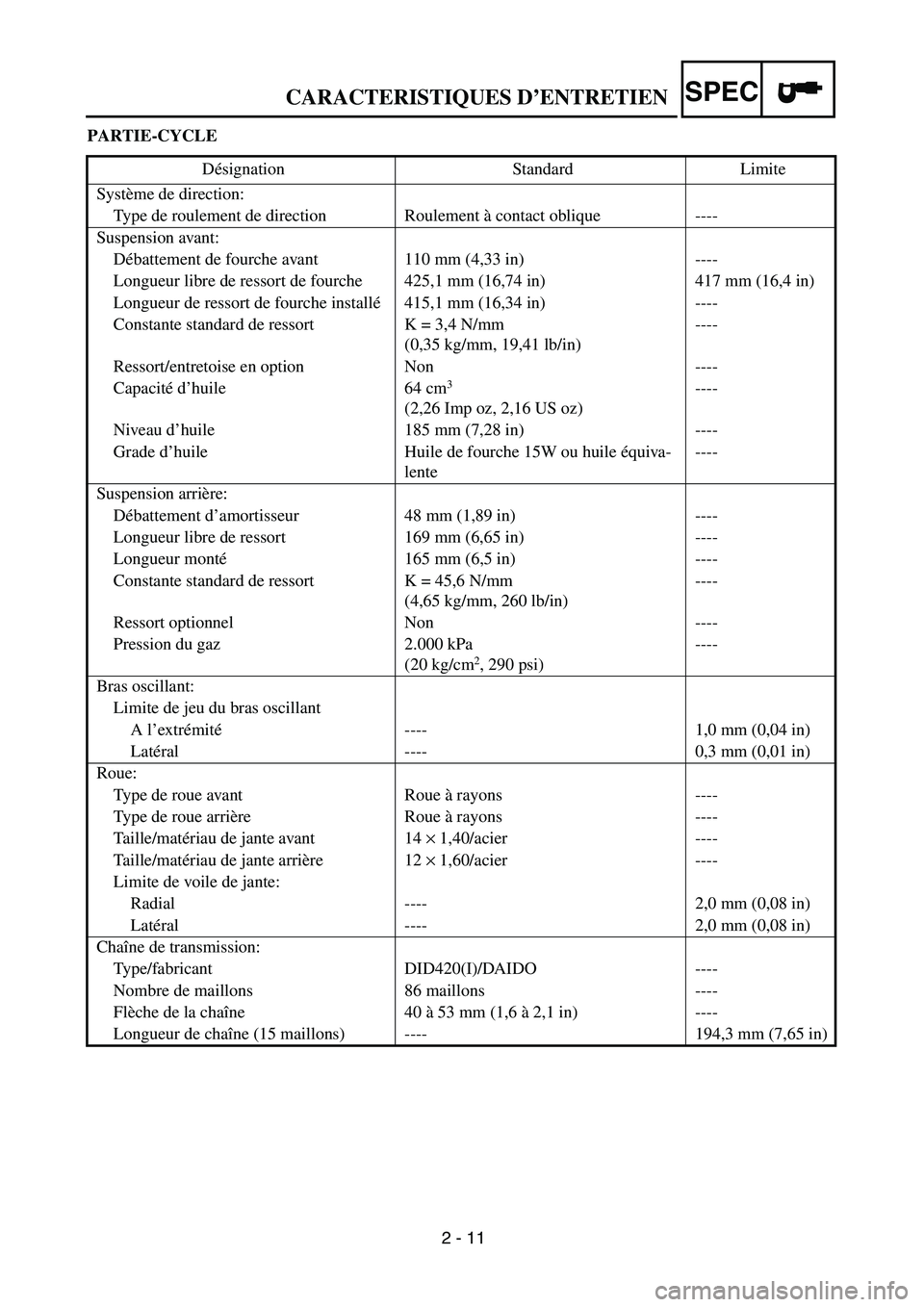
PARTIE-CYCLE
Désignation Standard Limite
Système de direction:
Type de roulement de direction Roulement à contact oblique ----
Suspension avant:
Débattement de fourche avant 110 mm (4,33 in) ----
Longueur libre de ressort de fourche 425,1 mm (16,74 in) 417 mm (16,4 in)
Longueur de ressort de fourche installé415,1 mm (16,34 in) ----
Constante standard de ressort K = 3,4 N/mm
(0,35 kg/mm, 19,41 lb/in)----
Ressort/entretoise en option Non ----
Capacité d’huile 64 cm
3
(2,26 Imp oz, 2,16 US oz) ----
Niveau d’huile 185 mm (7,28 in) ----
Grade d’huile Huile de fourche 15W ou huile équiva-
lente----
Suspension arrière:
Débattement d’amortisseur 48 mm (1,89 in) ----
Longueur libre de ressort 169 mm (6,65 in) ----
Longueur monté165 mm (6,5 in) ----
Constante standard de ressort K = 45,6 N/mm
(4,65 kg/mm, 260 lb/in)----
Ressort optionnel Non ----
Pression du gaz 2.000 kPa
(20 kg/cm
2, 290 psi)----
Bras oscillant:
Limite de jeu du bras oscillant
A l’extrémité---- 1,0 mm (0,04 in)
Latéral ---- 0,3 mm (0,01 in)
Roue:
Type de roue avant Roue à rayons ----
Type de roue arrière Roue à rayons ----
Taille/matériau de jante avant 14 × 1,40/acier ----
Taille/matériau de jante arrière 12 × 1,60/acier ----
Limite de voile de jante:
Radial ---- 2,0 mm (0,08 in)
Latéral ---- 2,0 mm (0,08 in)
Chaîne de transmission:
Type/fabricant DID420(I)/DAIDO ----
Nombre de maillons 86 maillons ----
Flèche de la chaîne 40 à 53 mm (1,6 à 2,1 in) ----
Longueur de chaîne (15 maillons) ---- 194,3 mm (7,65 in)
Page 110 of 364
2 - 18
SPEC
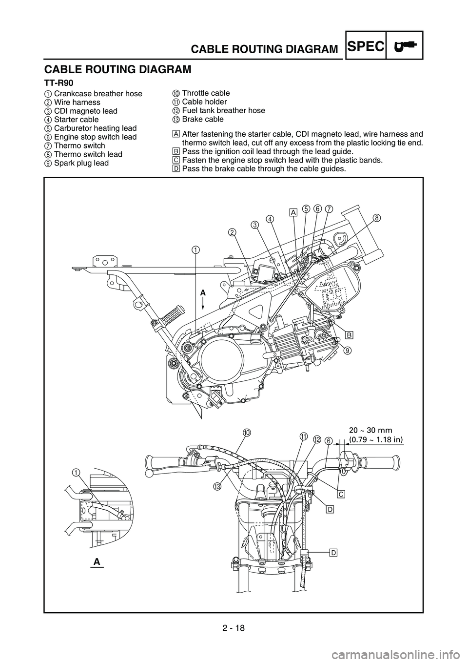
CABLE ROUTING DIAGRAM
TT-R90
1Crankcase breather hose
2Wire harness
3CDI magneto lead
4Starter cable
5Carburetor heating lead
6Engine stop switch lead
7Thermo switch
8Thermo switch lead
9Spark plug lead0Throttle cable
ACable holder
BFuel tank breather hose
CBrake cable
ÅAfter fastening the starter cable, CDI magneto lead, wire harness and
thermo switch lead, cut off any excess from the plastic locking tie end.
ıPass the ignition coil lead through the lead guide.
ÇFasten the engine stop switch lead with the plastic bands.
ÎPass the brake cable through the cable guides.
12345
9
0
B A
6
C 1Å
ı
Ç
Î
Î
A
A
67
8
20 ~ 30 mm
(0.79 ~ 1.18 in)
CABLE ROUTING DIAGRAM