key YAMAHA TW125 2000 Owners Manual
[x] Cancel search | Manufacturer: YAMAHA, Model Year: 2000, Model line: TW125, Model: YAMAHA TW125 2000Pages: 86, PDF Size: 3.94 MB
Page 4 of 86

EAU00005
IMPORTANT MANUAL INFORMATION
1
2
3
4
5
6
7
8
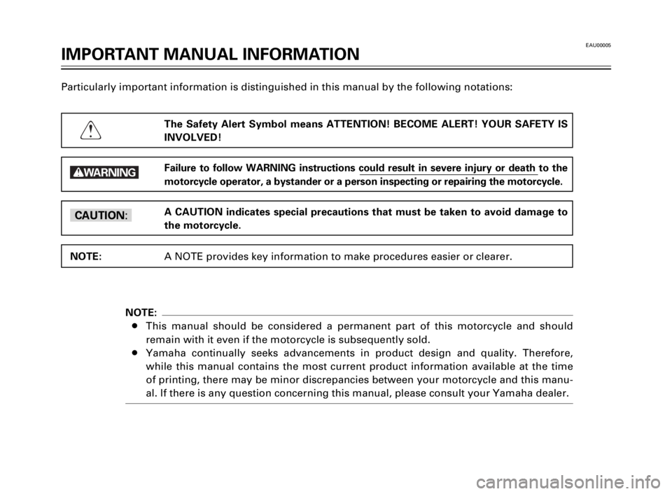
9Particularly important information is distinguished in this manual by the following notations:
The Safety Alert Symbol means ATTENTION! BECOME ALERT! YOUR SAFETY IS
INVOLVED!
Failure to follow WARNING instructions could result in severe injury or death to the
motorcycle operator, a bystander or a person inspecting or repairing the motorcycle.
A CAUTION indicates special precautions that must be taken to avoid damage to
the motorcycle.
A NOTE provides key information to make procedures easier or clearer.
Q
w
cC
NOTE:
NOTE:
8This manual should be considered a permanent part of this motorcycle and should
remain with it even if the motorcycle is subsequently sold.
8Yamaha continually seeks advancements in product design and quality. Therefore,
while this manual contains the most current product information available at the time
of printing, there may be minor discrepancies between your motorcycle and this manu-
al. If there is any question concerning this manual, please consult your Yamaha dealer.
5EK-9-E1 (TW125)<3.1> 4/6/0 11:50 PM Page 2
Page 8 of 86

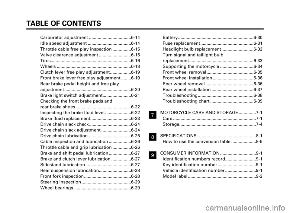
Carburetor adjustment ..................................6-14
Idle speed adjustment ...................................6-14
Throttle cable free play inspection ...............6-15
Valve clearance adjustment ..........................6-15
Tires.................................................................6-16
Wheels ............................................................6-18
Clutch lever free play adjustment .................6-19
Front brake lever free play adjustment ........6-19
Rear brake pedal height and free play
adjustment ......................................................6-20
Brake light switch adjustment.......................6-21
Checking the front brake pads and
rear brake shoes .............................................6-22
Inspecting the brake fluid level .....................6-22
Brake fluid replacement.................................6-23
Drive chain slack check ..................................6-24
Drive chain slack adjustment ........................6-24
Drive chain lubrication...................................6-25
Cable inspection and lubrication ..................6-26
Throttle cable and grip lubrication ...............6-26
Brake and shift pedal lubrication ..................6-27
Brake and clutch lever lubrication ................6-27
Sidestand lubrication .....................................6-27
Rear suspension lubrication..........................6-28
Front fork inspection ......................................6-28
Steering inspection ........................................6-29
Wheel bearings ..............................................6-29Battery .............................................................6-30
Fuse replacement ...........................................6-31
Headlight bulb replacement ..........................6-32
Turn signal and taillight bulb
replacement ....................................................6-33
Supporting the motorcycle ...........................6-34
Front wheel removal ......................................6-35
Front wheel installation .................................6-36
Rear wheel removal .......................................6-36
Rear wheel installation ..................................6-37
Troubleshooting .............................................6-38
Troubleshooting chart ...................................6-39
MOTORCYCLE CARE AND STORAGE ..............7-1
Care ...................................................................7-1
Storage..............................................................7-4
SPECIFICATIONS................................................8-1
How to use the conversion table ....................8-5
CONSUMER INFORMATION .............................9-1
Identification numbers record.........................9-1
Key identification number ...............................9-1
Vehicle identification number .........................9-1
Model label .......................................................9-2
TABLE OF CONTENTS
1
2
3
4
5
6
7
8
9
7
8
9
5EK-9-E1 (TW125)<3.1> 4/6/0 11:50 PM Page 6
Page 13 of 86

3-1
EAU00027
INSTRUMENT AND CONTROL FUNCTIONS
1
2
3
4
5
6
7
8
9
EAU00028Main switch
The main switch controls the igni-
tion and lighting systems. Its oper-
ation is described below.
EAU00036ON
Electrical circuits are switched on.
The engine can be started. The key
cannot be removed in this position.
EAU00038OFF
All electrical circuits are switched
off. The key can be removed in this
position.
EAU00056Indicator lights
EAU00057Turn indicator light “5”
This indicator flashes when the
turn switch is moved to the left or
right.
EAU00063High beam indicator light “&”
This indicator comes on when the
headlight high beam is used.
1. Turn indicator light “5”
2. High beam indicator light “&”
3. Neutral indicator light “N”
EAU00061Neutral indicator light “N”
This indicator comes on when the
transmission is in neutral.
OFFON
312
5EK-9-E1 (TW125)<3.1> 4/6/0 11:50 PM Page 11
Page 17 of 86

3-5
INSTRUMENT AND CONTROL FUNCTIONS
1
2
3
4
5
6
7
8
9
EAU00162Rear brake pedal
The rear brake pedal is on the right
side of the motorcycle. Press down
on the brake pedal to apply the
rear brake.
1. Rear brake pedal
EAU01498Fuel tank cap
To open
Insert the key and turn it 1/4 turn
counterclockwise. Open the cap by
turning it counterclockwise.
To close
Turn the cap clockwise with the
key inserted. To remove the key,
turn it clockwise to the original
position.
1. Fuel tank cap
NOTE:
This tank cap cannot be closed
unless the key is in the lock. The
key cannot be removed if the cap is
not locked properly.
EW000023
w
Be sure the cap is properly
installed and locked in place
before riding the motorcycle.
11
5EK-9-E1 (TW125)<3.1> 4/6/0 11:50 PM Page 15
Page 20 of 86

3-8
INSTRUMENT AND CONTROL FUNCTIONS
1
2
3
4
5
6
7
8
9
EAU02976Starter (choke) “1”
Starting a cold engine requires a
richer air-fuel mixture. A separate
starter circuit supplies this mixture.
Move in direction ato turn on the
starter (choke).
Move in direction bto turn off the
starter (choke).
1. Starter (choke) “1”
EAU02934Steering lock
To lock the steering
Turn the handlebars all the way to
the right and open the steering
lock cover.
Insert the key and turn it 1/8 turn
counterclockwise. Then, push the
key in while turning the handlebars
slightly to the left and turn the key
1/8 turn clockwise.
Check that the steering is locked,
remove the key and close the lock
cover.
1. Steering lock
2. Cover
To unlock the steering
Insert the key, push it in and turn it
1/8 turn counterclockwise so that it
moves out. Then, release and
remove the key.
a
b
1
12
5EK-9-E1 (TW125)<3.1> 4/6/0 11:50 PM Page 18
Page 21 of 86

3-9
INSTRUMENT AND CONTROL FUNCTIONS
1
2
3
4
5
6
7
8
9
EAU01092Seat
To remove the seat, remove the
bolts.
1. Bolt (´2)
To install the seat, insert the pro-
jection on the front of the seat into
the holder and push down on the
seat, then tighten the bolts.
NOTE:
Make sure that the seat is securely
fitted.
1. Projection
2. Seat holder
EAU00260Helmet holder
To open the helmet holder, insert
the key in the lock and turn it as
shown. To lock the helmet holder,
replace the holder in its original
position.
EW000030
w
Never ride with a helmet in the
helmet holder. The helmet may hit
objects, causing loss of control
and possibly an accident.
1. Helmet holder
1
1
1
2
5EK-9-E1 (TW125)<3.1> 4/6/0 11:50 PM Page 19
Page 32 of 86

5-6
OPERATION AND IMPORTANT RIDING POINTS
1
2
3
4
5
6
7
8
9
RES
ONFUEL
OFF
EAU00457Parking
When parking the motorcycle, stop
the engine and remove the ignition
key. Turn the fuel cock to “OFF”
whenever stopping the engine.
EW000058
w
The exhaust system is hot. Park
the motorcycle in a place where
pedestrians or children are not
likely to touch the motorcycle. Do
not park the motorcycle on a slope
or soft ground; the motorcycle
may overturn.
5EK-9-E1 (TW125)<3.1> 4/6/0 11:50 PM Page 30
Page 82 of 86

EAU01039
CONSUMER INFORMATION
1
2
3
4
5
6
7
8
9
9-1
EAU02944Identification number
records
Record the key identification num-
ber, vehicle identification number
and model label information in the
spaces provided for assistance
when ordering spare parts from a
Yamaha dealer or for reference in
case the vehicle is stolen.
1. KEY IDENTIFICATION
NUMBER:
2. VEHICLE IDENTIFICATION
NUMBER:
3. MODEL LABEL INFORMATION:
EAU01041Key identification number
The key identification number is
stamped on the key tag.
Record this number in the space
provided and use it for reference
when obtaining a new key.
1. Key identification number
EAU01043Vehicle identification
number
The vehicle identification number
is stamped into the steering head
pipe.
Record this number in the space
provided.
NOTE:
The vehicle identification number
is used to identify your motorcycle
and may be used to register your
motorcycle with the licensing
authority in your state.
1. Vehicle identification number
1
1
1
6
5EK-9-E1 (TW125)<3.1> 4/6/0 11:50 PM Page 80