clock YAMAHA TW125 2003 Owners Manual
[x] Cancel search | Manufacturer: YAMAHA, Model Year: 2003, Model line: TW125, Model: YAMAHA TW125 2003Pages: 88, PDF Size: 1.71 MB
Page 16 of 88

3-5
INSTRUMENT AND CONTROL FUNCTIONS
3
EAU00158
Brake lever
The brake lever is located at the right
handlebar grip. To apply the front
brake, pull the lever toward the han-
dlebar grip.
1
1. Brake lever
EAU00162
Brake pedal
The brake pedal is on the right side
of the motorcycle. To apply the rear
brake, press down on the brake
pedal.
1
1. Brake pedal
EAU00177*
Fuel tank cap
To remove the fuel tank cap
1. Insert the key into the lock and
turn it 1/3 turn counterclockwise.
2. Turn the fuel tank cap 1/3 turn
counterclockwise and pull it off.
1
a
1. Fuel tank cap
a. Unlock.
5RS-9-E1 (TW125) 8/23/02 11:37 AM Page 15
Page 17 of 88

3-6
To install the fuel tank cap
1. Insert the fuel tank cap into the
tank opening with the key insert-
ed in the lock, and then turn the
cap 1/3 turn clockwise.
2. Turn the key 1/3 turn clockwise,
and then remove it.
NOTE:
The fuel tank cap cannot be installed
unless the key is in the lock. In addi-
tion, the key cannot be removed if the
cap is not properly installed and
locked.
EW000023
w
Make sure that the fuel tank cap is
properly closed and locked before
riding.
INSTRUMENT AND CONTROL FUNCTIONS
3
EAU03753
Fuel
Make sure that there is sufficient fuel
in the tank. Fill the fuel tank to the
bottom of the filler tube as shown.
EW000130
w
8Do not overfill the fuel tank,
otherwise it may overflow
when the fuel warms up and
expands.
8Avoid spilling fuel on the hot
engine.
1
2
1. Filler tube
2. Fuel level
EAU00185
cC
Immediately wipe off spilled fuel
with a clean, dry, soft cloth, since
fuel may deteriorate painted sur-
faces or plastic parts.
EAU04284
Recommended fuel:
REGULAR UNLEADED
GASOLINE ONLY
Fuel tank capacity:
Total amount:
7.0 L
Reserve amount:
1.7 L
5RS-9-E1 (TW125) 8/23/02 11:37 AM Page 16
Page 19 of 88

3-8
RES
This indicates reserve. If you run out
of fuel while riding, move the lever to
this position. Fill the tank at the first
opportunity. Be sure to set the lever
back to “ON” after refueling!
INSTRUMENT AND CONTROL FUNCTIONS
3
OFF
ONFUEL RES
1
RES
1. Arrow mark positioned over “RES”
EAU04038
Starter (choke) knob“1”
Starting a cold engine requires a rich-
er air-fuel mixture, which is supplied
by the starter (choke).
Move the knob in direction ato turn
on the starter (choke).
Move the knob in direction bto turn
off the starter (choke).
a
b
1
1. Starter (choke) knob “1”
EAU03342
Steering lock
To lock the steering
1. Turn the handlebar all the way to
the right.
2. Open the steering lock cover,
and then insert the steering lock
key.
3. Turn the key 1/8 turn counter-
clockwise, push it in while turning
the handlebar slightly to the left,
and then turn the key 1/8 turn
clockwise.
21
1. Steering lock cover
2. Steering lock
RES: Reserve position
5RS-9-E1 (TW125) 8/23/02 11:37 AM Page 18
Page 20 of 88

3-9
INSTRUMENT AND CONTROL FUNCTIONS
3 4. Check that the steering is locked,
remove the key, and then close
the lock cover.
To unlock the steering
1. Open the steering lock cover,
and then insert the steering lock
key.
2. Push the key in, turn it 1/8 turn
counterclockwise so that it
moves out, and then release it.
3. Remove the key, and then close
the lock cover.
EAU01092
Seat
To remove the seat
Remove the bolts, and then pull the
seat off.
1
1. Bolt (×2)
To install the seat
1. Insert the projection on the front
of the seat into the seat holder
as shown.
2. Place the seat in the original
position, and then tighten the
bolts.
NOTE:
Make sure that the seat is properly
secured before riding.
12
1. Projection
2. Seat holder
5RS-9-E1 (TW125) 8/23/02 11:37 AM Page 19
Page 68 of 88

6-36
PERIODIC MAINTENANCE AND MINOR REPAIR
6
EAU03497
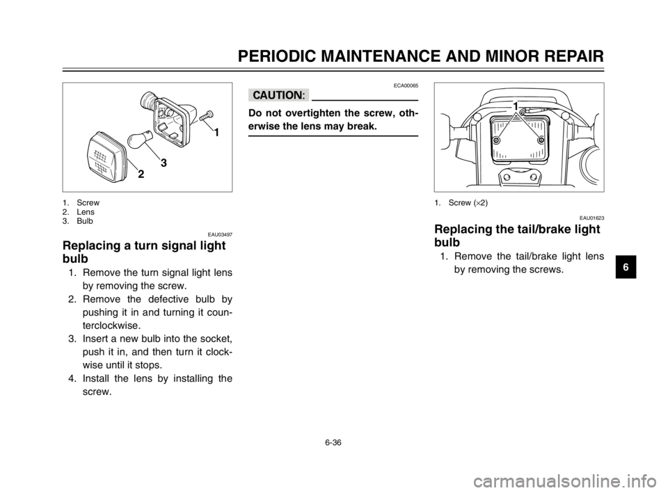
Replacing a turn signal light
bulb
1. Remove the turn signal light lens
by removing the screw.
2. Remove the defective bulb by
pushing it in and turning it coun-
terclockwise.
3. Insert a new bulb into the socket,
push it in, and then turn it clock-
wise until it stops.
4. Install the lens by installing the
screw.
1
2
3
1. Screw
2. Lens
3. Bulb
ECA00065
cC
Do not overtighten the screw, oth-
erwise the lens may break.
EAU01623
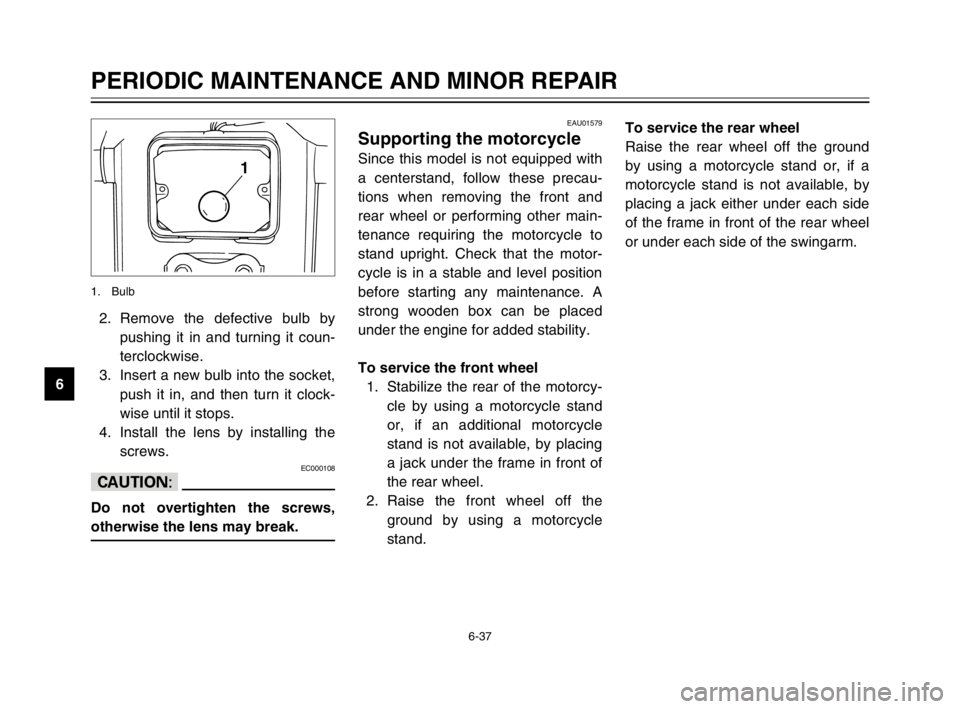
Replacing the tail/brake light
bulb
1. Remove the tail/brake light lens
by removing the screws.
1
1. Screw (×2)
5RS-9-E1 (TW125) 8/23/02 11:37 AM Page 67
Page 69 of 88

6-37
PERIODIC MAINTENANCE AND MINOR REPAIR
62. Remove the defective bulb by
pushing it in and turning it coun-
terclockwise.
3. Insert a new bulb into the socket,
push it in, and then turn it clock-
wise until it stops.
4. Install the lens by installing the
screws.
EC000108
cC
Do not overtighten the screws,
otherwise the lens may break.
1
1. Bulb
EAU01579
Supporting the motorcycle
Since this model is not equipped with
a centerstand, follow these precau-
tions when removing the front and
rear wheel or performing other main-
tenance requiring the motorcycle to
stand upright. Check that the motor-
cycle is in a stable and level position
before starting any maintenance. A
strong wooden box can be placed
under the engine for added stability.
To service the front wheel
1. Stabilize the rear of the motorcy-
cle by using a motorcycle stand
or, if an additional motorcycle
stand is not available, by placing
a jack under the frame in front of
the rear wheel.
2. Raise the front wheel off the
ground by using a motorcycle
stand.To service the rear wheel
Raise the rear wheel off the ground
by using a motorcycle stand or, if a
motorcycle stand is not available, by
placing a jack either under each side
of the frame in front of the rear wheel
or under each side of the swingarm.
5RS-9-E1 (TW125) 8/23/02 11:37 AM Page 68