light YAMAHA TW200 1998 Owners Manual
[x] Cancel search | Manufacturer: YAMAHA, Model Year: 1998, Model line: TW200, Model: YAMAHA TW200 1998Pages: 74, PDF Size: 1.58 MB
Page 6 of 74

EAU00009
TABLE OF CONTENTS
1
2
3
4
5
6
7
8
9 GIVE SAFETY THE RIGHT OF WAY ..................1-1
DESCRIPTION .....................................................2-1
Left view............................................................2-1
Right view .........................................................2-2
Controls/Instruments .......................................2-3
INSTRUMENT AND CONTROL
FUNCTIONS ........................................................3-1
Main switch/Steering lock ...............................3-1
Indicator lights..................................................3-2
Speedometer ....................................................3-2
Handlebar switches..........................................3-3
Clutch lever .......................................................3-4
Shift pedal.........................................................3-4
Front brake lever ..............................................3-5
Rear brake pedal ..............................................3-5
Fuel tank cap.....................................................3-5
Fuel ....................................................................3-6
Fuel cock ...........................................................3-7
Starter (choke) “1” .........................................3-8
Kick starter ........................................................3-8
Seat ...................................................................3-9
Helmet holder ...................................................3-9
Rear shock absorber ......................................3-10
Rear carrier .....................................................3-10Sidestand ........................................................3-10
Sidestand/clutch switch operation check .....3-11
PRE-OPERATION CHECKS.................................4-1
Pre-operation check list ...................................4-1
OPERATION AND IMPORTANT RIDING
POINTS................................................................5-1
Starting and warming up a cold engine.........5-1
Starting a warm engine ...................................5-4
Shifting..............................................................5-4
Engine break-in ................................................5-5
Parking ..............................................................5-6
PERIODIC MAINTENANCE AND MINOR
REPAIR ................................................................6-1
Tool kit ..............................................................6-1
Periodic maintenance and lubrication............6-3
Cowling and panel removal and
installation ........................................................6-6
Cowling A .........................................................6-6
Panel A ..............................................................6-7
Panel B ..............................................................6-7
Spark plug inspection ......................................6-7
Engine oil ..........................................................6-8
Air filter ...........................................................6-12
1
2
3
4
5
6
5FY-28199-EX (TW200) 4/16/02 5:38 PM Page 5
Page 7 of 74

Carburetor adjustment ..................................6-13
Idle speed adjustment ...................................6-13
Throttle cable free play inspection ...............6-14
Cam chain adjustment ...................................6-14
Valve clearance adjustment ..........................6-14
Tires.................................................................6-15
Wheels ............................................................6-17
Clutch lever free play adjustment .................6-18
Front brake lever free play adjustment ........6-18
Rear brake pedal height and free play
adjustment ......................................................6-19
Brake light switch adjustment.......................6-20
Checking the brake shoes..............................6-21
Drive chain slack check ..................................6-21
Drive chain slack adjustment ........................6-22
Drive chain lubrication...................................6-23
Cable inspection and lubrication ..................6-24
Throttle cable and grip lubrication ...............6-24
Brake and shift pedal lubrication ..................6-24
Brake and clutch lever lubrication ................6-25
Sidestand lubrication .....................................6-25
Rear suspension lubrication..........................6-25
Front fork inspection ......................................6-26
Steering inspection ........................................6-26
Wheel bearings ..............................................6-27
Battery .............................................................6-27Fuse replacement ...........................................6-29
Headlight bulb replacement ..........................6-30
Supporting the motorcycle ...........................6-31
Front wheel removal ......................................6-31
Front wheel installation .................................6-32
Rear wheel removal .......................................6-33
Rear wheel installation ..................................6-33
Troubleshooting .............................................6-34
Troubleshooting chart ...................................6-35
CLEANING AND STORAGE ...............................7-1
Cleaning ............................................................7-1
Storage..............................................................7-2
SPECIFICATIONS................................................8-1
How to use the conversion table ....................8-4
CONSUMER INFORMATION .............................9-1
Identification numbers record.........................9-1
Key identification number ...............................9-1
Vehicle identification number .........................9-1
Model label .......................................................9-2
TABLE OF CONTENTS
1
2
3
4
5
6
7
8
9
7
8
9
5FY-28199-EX (TW200) 4/16/02 5:38 PM Page 6
Page 9 of 74

EAU00026
DESCRIPTION
1
2
3
4
5
6
7
8
9
2-1
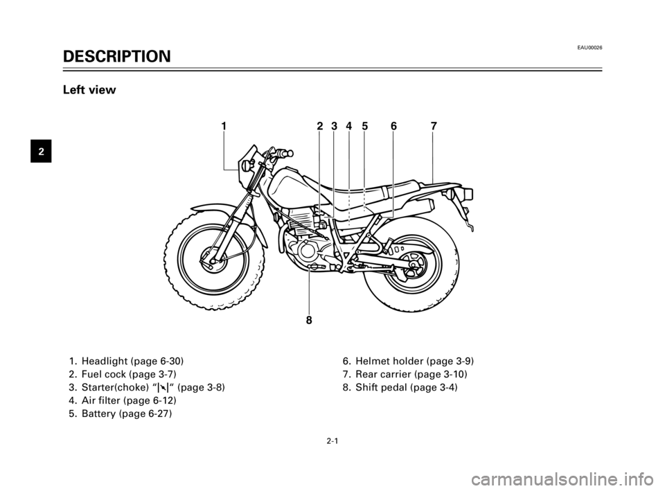
1. Headlight (page 6-30)
2. Fuel cock (page 3-7)
3. Starter(choke) “1“ (page 3-8)
4. Air filter (page 6-12)
5. Battery (page 6-27)6. Helmet holder (page 3-9)
7. Rear carrier (page 3-10)
8. Shift pedal (page 3-4)
123456 7
8
Left view
5FY-28199-EX (TW200) 4/16/02 5:38 PM Page 8
Page 12 of 74

3-1
LOCKOFFON
EAU00029
Main switch/Steering lock
The main switch controls the igni-
tion and lighting systems. Its oper-
ation is described below.
EAU00032
ON:
All electrical circuits are switched
on, and the headlight, meter light,
taillight and front position lights
come on. The engine can be start-
ed. The key cannot be removed in
this position.
EAU00038
OFF:
All electrical circuits are switched
off. The key can be removed in this
position.
EAU00042
LOCK:
The steering is locked in this posi-
tion and all electrical circuits are
switched off.
The key can be removed in this
position.
To lock the steering, turn the han-
dlebars all the way to the left. With
the key at “OFF”, push it into the
main switch and release it, turn it
counterclockwise to “LOCK” and
remove it.
To release the lock, turn the key to
“OFF”.
EW000016
w
Never turn the key to “OFF” or
“LOCK” when the motorcycle is
moving. The electrical circuits will
be switched off which may result
in loss of control or an accident. Be
sure the motorcycle is stopped
before turning the key to “OFF” or
“LOCK”.
EAU00027
INSTRUMENT AND CONTROL FUNCTIONS
1
2
3
4
5
6
7
8
9
5FY-28199-EX (TW200) 4/16/02 5:38 PM Page 11
Page 13 of 74

3-2
123
EAU00056Indicator lights
EAU00059Turn indicator light “TURN”
This indicator flashes when the
turn switch is moved to the left or
right.
EAU00062Neutral indicator light “NEUTRAL”
This indicator comes on when the
transmission is in neutral.
1. Turn indicator light “TURN”
2. High beam indicator light
“HIGH BEAM”
3. Neutral indicator light “NEUTRAL”
EAU00064
High beam indicator light “HIGH
BEAM”
This indicator comes on when the
headlight high beam is used.
INSTRUMENT AND CONTROL FUNCTIONS
1
2
3
4
5
6
7
8
9
1
2
EAU00098Speedometer
The speedometer shows riding
speed.
This speedometer is equipped with
an odometer.
1. Speedometer
2. Odometer
5FY-28199-EX (TW200) 4/16/02 5:38 PM Page 12
Page 14 of 74

3-3
INSTRUMENT AND CONTROL FUNCTIONS
1
2
3
4
5
6
7
8
9
1
23
EAU00118Handlebar switches
EAU00122Dimmer switch “LIGHTS”
Turn the switch to “HI” for the high
beam and to “LO” for the low
beam.
EAU00128Turn signal switch “TURN”
This is a three-position switch. The
center position is off.
Turn to “L” to turn on the left
flasher, and to “R” for the right
flasher. Be sure to turn the switch
off after completing a turn.
1. Dimmer switch “LIGHTS”
2. Turn signal switch “TURN”
3. Horn switch “HORN”
EAU00130Horn switch “HORN”
Press the switch to sound the horn.1
2
EAU00137
Engine stop switch “ENGINE
STOP”
The engine stop switch is a safety
device for use in an emergency
such as when the motorcycle over-
turns or if trouble occurs in the
throttle system. Turn the switch to
“RUN” to start the engine. In case
of emergency, turn the switch to
“OFF” to stop the engine.
1. Engine stop switch “ENGINE STOP”
2. Start switch “START”
5FY-28199-EX (TW200) 4/16/02 5:38 PM Page 13
Page 19 of 74

3-8
INSTRUMENT AND CONTROL FUNCTIONS
1
2
3
4
5
6
7
8
9
ab
1
EAU00210Starter(choke) “1”
Starting a cold engine requires a
richer air-fuel mixture. A separate
starter circuit supplies this mixture.
Move in direction ato turn on the
starter(choke).
Move in direction bto turn off the
starter(choke).
1. Starter (choke) “1”
RES: This indicates reserve. If you
run out of fuel while riding,
set the fuel cock to this posi-
tion.
Fill the tank at the first oppor-
tunity. Be sure to set the fuel
cock back to “ON” after refu-
eling!
OFF
ONFUEL RES
1
RES
1. Arrow mark
RES
EAU00212Kick starter
Rotate the kick starter away from
the engine. Push the starter down
lightly with your foot until the
gears engage, then kick smoothly
and forcefully to start the engine.
This model has a primary-coupled
kick starter so the engine can be
started in any gear if the clutch is
disengaged. However, shifting to
neutral before starting is recom-
mended.
1
1. Kick starter
5FY-28199-EX (TW200) 4/16/02 5:38 PM Page 18
Page 24 of 74

4-2
PRE-OPERATION CHECKS
1
2
3
4
5
6
7
8
9
NOTE:
Pre-operation checks should be made each time the motorcycle is used. Such an inspection can be accom-
plished in a very short time; and the added safety it assures is more than worth the time involved.
w
If any item in the PRE-OPERATION CHECKS is not working properly, have it inspected and repaired before oper-
ating the motorcycle.
ITEM CHECKS PAGE
Fuel tank9Check fuel level.
3-5 ~ 3-6
9Fill with fuel if necessary.
Lights, signals and
9Check for proper operation. 6-30
switches
Battery9Check fluid level.
6-27 ~ 6-29
9Fill with distilled water if necessary.
5FY-28199-EX (TW200) 4/16/02 5:38 PM Page 23
Page 27 of 74

5-3
OPERATION AND IMPORTANT RIDING POINTS
1
2
3
4
5
6
7
8
91. Turn the fuel cock to “ON”.
2. Turn the main switch to ON”
and the engine stop switch to
“RUN”.
3. Shift transmission into neutral.
NOTE:
When the transmission is in neu-
tral, the neutral indicator light
should be on. If the light does not
come on, ask a Yamaha dealer to
inspect it.
4. Turn on the starter and com-
pletely close the throttle grip.
5. Start the engine by pushing
the start switch or by kicking
the kick starter.
NOTE:
If the engine fails to start, release
the start switch, wait a few sec-
onds, then try again. Each attempt
should be as short as possible to
preserve the battery. Do not crank
the engine more than 10 seconds
on any one attempt. If the engine
does not start with the starter
motor, kick the kick starter to start
the engine.
6. After starting the engine, move
the starter to the halfway posi-
tion.
NOTE:
For maximum engine life, always
warm up the engine before starting
off. Never accelerate hard with a
cold engine.
7. After warming up the engine,
turn off the starter completely.
NOTE:
The engine is warm when it
responds normally to the throttle
with the starter turned off.
5FY-28199-EX (TW200) 4/16/02 5:38 PM Page 26
Page 28 of 74

5-4
OPERATION AND IMPORTANT RIDING POINTS
1
2
3
4
5
6
7
8
9
EAU00423
Shifting
The transmission lets you control
the amount of power you have
available at a given speed for start-
ing, accelerating, climbing hills,
etc. The use of the shift pedal is
shown in the illustration.
To shift into neutral, depress the
shift pedal repeatedly until it reach-
es the end of its travel, then raise
the pedal slightly.
EC000048
cC
1. Do not coast for long periods
with the engine off, and do
not tow the motorcycle a long
distance. Even with gears in
neutral, the transmission is
only properly lubricated when
the engine is running.
Inadequate lubrication may
damage the transmission.
2. Always use the clutch when
changing gears. The engine,
transmission, and driveline are
not designed to withstand the
shock of forced shifting and
can be damaged by shifting
without using the clutch.
1
N5
4
3
2
1
N. Neutral
1. Shift pedal
EAU01258Starting a warm engine
The starter (choke) is not required
when the engine is warm.
EC000046
cC
See the “Engine break-in” section
prior to operating the motorcycle
for the first time.
5FY-28199-EX (TW200) 4/16/02 5:38 PM Page 27