lock YAMAHA TW200 2002 Owners Manual
[x] Cancel search | Manufacturer: YAMAHA, Model Year: 2002, Model line: TW200, Model: YAMAHA TW200 2002Pages: 74, PDF Size: 1.57 MB
Page 6 of 74

EAU00009
TABLE OF CONTENTS
1
2
3
4
5
6
7
8
9 GIVE SAFETY THE RIGHT OF WAY ..................1-1
DESCRIPTION .....................................................2-1
Left view............................................................2-1
Right view .........................................................2-2
Controls/Instruments .......................................2-3
INSTRUMENT AND CONTROL
FUNCTIONS ........................................................3-1
Main switch/Steering lock ...............................3-1
Indicator lights..................................................3-2
Speedometer ....................................................3-2
Handlebar switches..........................................3-3
Clutch lever .......................................................3-4
Shift pedal.........................................................3-4
Front brake lever ..............................................3-5
Rear brake pedal ..............................................3-5
Fuel tank cap.....................................................3-5
Fuel ....................................................................3-6
Fuel cock ...........................................................3-7
Starter (choke) “1” .........................................3-8
Kick starter ........................................................3-8
Seat ...................................................................3-9
Helmet holder ...................................................3-9
Rear shock absorber ......................................3-10
Rear carrier .....................................................3-10Sidestand ........................................................3-10
Sidestand/clutch switch operation check .....3-11
PRE-OPERATION CHECKS.................................4-1
Pre-operation check list ...................................4-1
OPERATION AND IMPORTANT RIDING
POINTS................................................................5-1
Starting and warming up a cold engine.........5-1
Starting a warm engine ...................................5-4
Shifting..............................................................5-4
Engine break-in ................................................5-5
Parking ..............................................................5-6
PERIODIC MAINTENANCE AND MINOR
REPAIR ................................................................6-1
Tool kit ..............................................................6-1
Periodic maintenance and lubrication............6-3
Cowling and panel removal and
installation ........................................................6-6
Cowling A .........................................................6-6
Panel A ..............................................................6-7
Panel B ..............................................................6-7
Spark plug inspection ......................................6-7
Engine oil ..........................................................6-8
Air filter ...........................................................6-12
1
2
3
4
5
6
5FY-9-E0 (TW200) 7/29/02 10:54 AM Page 5
Page 12 of 74

3-1
LOCKOFFON
EAU00029
Main switch/Steering lock
The main switch controls the igni-
tion and lighting systems. Its oper-
ation is described below.
EAU00032
ON:
All electrical circuits are switched
on, and the headlight, meter light,
taillight and front position lights
come on. The engine can be start-
ed. The key cannot be removed in
this position.
EAU00038
OFF:
All electrical circuits are switched
off. The key can be removed in this
position.
EAU00042
LOCK:
The steering is locked in this posi-
tion and all electrical circuits are
switched off.
The key can be removed in this
position.
To lock the steering, turn the han-
dlebars all the way to the left. With
the key at “OFF”, push it into the
main switch and release it, turn it
counterclockwise to “LOCK” and
remove it.
To release the lock, turn the key to
“OFF”.
EW000016
w
Never turn the key to “OFF” or
“LOCK” when the motorcycle is
moving. The electrical circuits will
be switched off which may result
in loss of control or an accident. Be
sure the motorcycle is stopped
before turning the key to “OFF” or
“LOCK”.
EAU00027
INSTRUMENT AND CONTROL FUNCTIONS
1
2
3
4
5
6
7
8
9
5FY-9-E0 (TW200) 7/29/02 10:54 AM Page 11
Page 16 of 74

3-5
INSTRUMENT AND CONTROL FUNCTIONS
1
2
3
4
5
6
7
8
9
1
2
EAU00158Front brake lever
The front brake lever is located on
the right handlebar. Pull it toward
the handlebar to apply the front
brake.
1. Unlock
2. Open
EAU00162Rear brake pedal
The rear brake pedal is on the right
side of the motorcycle. Press down
on the brake pedal to apply the
rear brake.
EAU00177
Fuel tank cap
TO OPEN:
Insert the key and turn it 1/4 turn
counterclockwise. Turn the cap 1/3
turn counterclockwise and remove
it from the tank.
TO CLOSE:
Put the cap in the filler neck and
turn it 1/3 turn clockwise. Lock the
cap by turning the key 1/4 turn
clockwise, and remove the key.
5FY-9-E0 (TW200) 7/29/02 10:54 AM Page 15
Page 17 of 74

1
2
EAU01183Fuel
Make sure there is sufficient fuel in
the tank. Fill the fuel tank to the
bottom of the filler tube as shown
in the illustration.
EW000130
w
Do not overfill the fuel tank. Avoid
spilling fuel on the hot engine. Do
not fill the fuel tank above the bot-
tom of the filler tube or it may
overflow when the fuel heats up
later and expands.
EAU00185
cC
Always wipe off spilled fuel imme-
diately with a dry and clean soft
cloth. Fuel may deteriorate painted
surfaces or plastic parts.
1. Filler tube
2. Fuel level
NOTE:
The tank cap cannot be reinstalled
unless it is unlocked. The key must
remain in the cap until the cap is
properly installed and locked onto
the fuel tank.
EW000023
w
Be sure the cap is properly
installed and locked in place
before riding the motorcycle.
3-6
INSTRUMENT AND CONTROL FUNCTIONS
1
2
3
4
5
6
7
8
9
5FY-9-E0 (TW200) 7/29/02 10:54 AM Page 16
Page 20 of 74

3-9
INSTRUMENT AND CONTROL FUNCTIONS
1
2
3
4
5
6
7
8
9
EAU01092Seat
To remove the seat, remove the
bolts.
1
1. Bolt (×2)
To install the seat, insert the pro-
jection on the front of the seat into
the holder and push down on the
seat, then tighten the bolts.
NOTE:
Make sure that the seat is securely
fitted.
1
2
EAU00260Helmet holder
To open the helmet holder, insert
the key in the lock and turn it as
shown. To lock the helmet holder,
replace the holder in its original
position.
EW000030
w
Never ride with a helmet in the
helmet holder. The helmet may hit
objects, causing loss of control
and possibly an accident.
1. Open
2. Helmet holder
5FY-9-E0 (TW200) 7/29/02 10:54 AM Page 19
Page 22 of 74

3-11
EW000044
w
This motorcycle must not be oper-
ated with the sidestand in the
down position. If the stand is not
properly retracted, it could contact
the ground and distract the opera-
tor, resulting in a possible loss of
control. Yamaha has designed into
this motorcycle a lockout system
to assist the operator in fulfilling
the responsibility of retracting the
sidestand. Please check carefully
the operating instructions listed
below and if there is any indication
of a malfunction, return the motor-
cycle to a Yamaha dealer immedi-
ately for repair.
INSTRUMENT AND CONTROL FUNCTIONS
1
2
3
4
5
6
7
8
9
EAU00331
Sidestand/clutch switch
operation check
Check the operation of the side-
stand switch and clutch switch
against the information below.
TURN THE MAIN SWITCH TO “ON”
AND THE ENGINE STOP SWITCH TO
“RUN”.
TRANSMISSION IS IN GEAR AND
SIDESTAND IS UP.
PULL IN CLUTCH LEVER AND
PUSH THE START SWITCH.
ENGINE WILL START.
CLUTCH SWITCH IS OK.
EW000045
w
If improper operation is noted,
consult a Yamaha dealer immedi-
ately.
SIDESTAND IS DOWN.
ENGINE WILL STALL.
SIDESTAND SWITCH IS OK.
5FY-9-E0 (TW200) 7/29/02 10:54 AM Page 21
Page 48 of 74

6-18
PERIODIC MAINTENANCE AND MINOR REPAIR
1
2
3
4
5
6
7
8
9
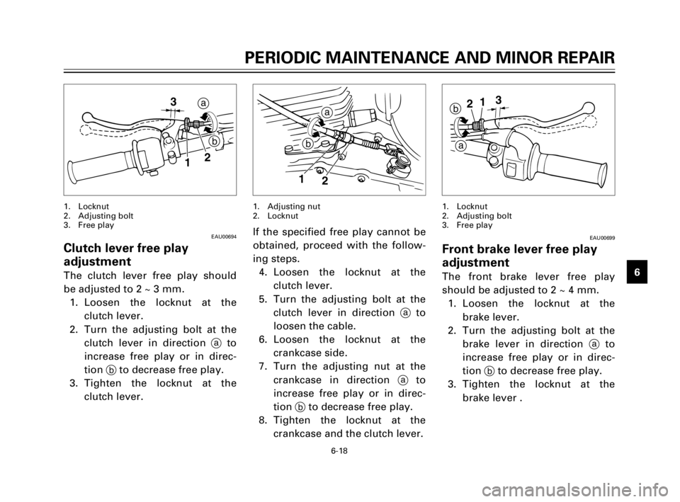
a
b 3
12
EAU00694
Clutch lever free play
adjustment
The clutch lever free play should
be adjusted to 2 ~ 3 mm.
1. Loosen the locknut at the
clutch lever.
2. Turn the adjusting bolt at the
clutch lever in direction ato
increase free play or in direc-
tion bto decrease free play.
3. Tighten the locknut at the
clutch lever.
1. Locknut
2. Adjusting bolt
3. Free play
If the specified free play cannot be
obtained, proceed with the follow-
ing steps.
4. Loosen the locknut at the
clutch lever.
5. Turn the adjusting bolt at the
clutch lever in direction ato
loosen the cable.
6. Loosen the locknut at the
crankcase side.
7. Turn the adjusting nut at the
crankcase in direction ato
increase free play or in direc-
tion bto decrease free play.
8. Tighten the locknut at the
crankcase and the clutch lever.
b
a213
EAU00699
Front brake lever free play
adjustment
The front brake lever free play
should be adjusted to 2 ~ 4 mm.
1. Loosen the locknut at the
brake lever.
2. Turn the adjusting bolt at the
brake lever in direction ato
increase free play or in direc-
tion bto decrease free play.
3. Tighten the locknut at the
brake lever .
1. Locknut
2. Adjusting bolt
3. Free play
a
b
1
2
1. Adjusting nut
2. Locknut
5FY-9-E0 (TW200) 7/29/02 10:54 AM Page 47
Page 49 of 74

6-19
PERIODIC MAINTENANCE AND MINOR REPAIR
1
2
3
4
5
6
7
8
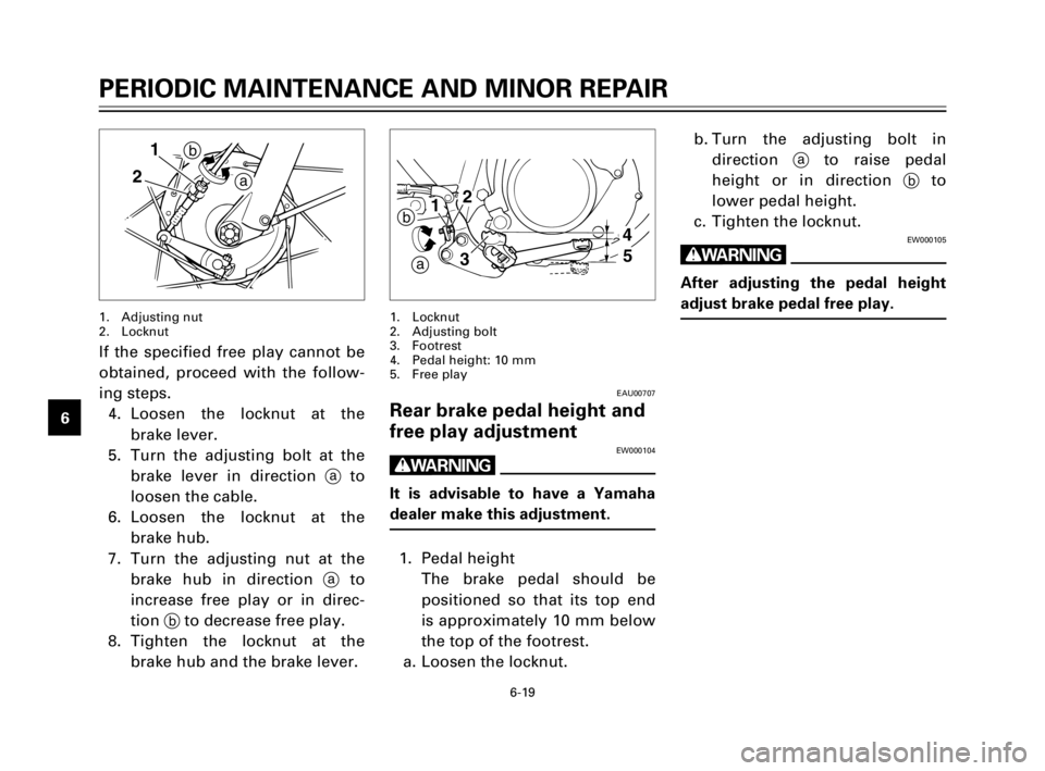
9b. Turn the adjusting bolt in
direction ato raise pedal
height or in direction bto
lower pedal height.
c. Tighten the locknut.
EW000105
w
After adjusting the pedal height
adjust brake pedal free play.
4
5 12
3
a b
EAU00707
Rear brake pedal height and
free play adjustment
EW000104
w
It is advisable to have a Yamaha
dealer make this adjustment.
1. Pedal height
The brake pedal should be
positioned so that its top end
is approximately 10 mm below
the top of the footrest.
a. Loosen the locknut.
1. Locknut
2. Adjusting bolt
3. Footrest
4. Pedal height: 10 mm
5. Free play
a b 1
2
If the specified free play cannot be
obtained, proceed with the follow-
ing steps.
4. Loosen the locknut at the
brake lever.
5. Turn the adjusting bolt at the
brake lever in direction ato
loosen the cable.
6. Loosen the locknut at the
brake hub.
7. Turn the adjusting nut at the
brake hub in direction ato
increase free play or in direc-
tion bto decrease free play.
8. Tighten the locknut at the
brake hub and the brake lever.
1. Adjusting nut
2. Locknut
5FY-9-E0 (TW200) 7/29/02 10:54 AM Page 48
Page 60 of 74

6-30
PERIODIC MAINTENANCE AND MINOR REPAIR
1
2
3
4
5
6
7
8
9
1
3. Remove the connector and the
bulb holder cover.
4. Turn the bulb holder counter-
clockwise to remove it and
remove the defective bulb.
EW000119
w
Keep flammable products and your
hands away from a bulb while it is
on, as it is hot. Do not touch a bulb
until it cools down.
5. Put a new bulb into position
and secure it in place with the
bulb holder.
1. Bulb holder cover
EAU01191
Headlight bulb replacement
This motorcycle is equipped with a
quartz bulb headlight. If the head-
light bulb burns out, replace it as
follows:
1. Remove cowling A. (See page
6-6 for cowling removal and
installation procedures.)
2. Remove the headlight unit.
1
EC000105
cC
Avoid touching the glass part of a
bulb. Keep it free from oil; other-
wise, the transparency of the
glass, life of the bulb, and lumi-
nous flux will be adversely affect-
ed. If oil gets on a bulb, thoroughly
clean it with a cloth moistened
with alcohol or lacquer thinner.
6. Install the bulb holder cover,
connector and headlight unit.
7. Install the cowling.
8. If the headlight beam adjust-
ment is necessary, ask a
Yamaha dealer to make that
adjustment.
1. Bulb holder
5FY-9-E0 (TW200) 7/29/02 10:54 AM Page 59
Page 66 of 74

7-1
EAU01010
CLEANING AND STORAGE
1
2
3
4
5
6
7
8
9
EAU01301A. CLEANING
Frequent, thorough cleaning of
your motorcycle will not only
enhance its appearance but will
improve its
general performance and extend
the useful life of many compo-
nents.
ECA00002
cC
8Improper cleaning can damage
the cowlings, panels and other
plastic parts. Use only a soft,
clean cloth or sponge with
mild detergent and water to
clean plastic.
8Do not use any harsh chemical
products on plastic parts. Be
sure to avoid using cloths or
sponges which have been in
contact with strong or abra-
sive cleaning products, solvent
or thinner, fuel (gasoline), rust
removers or inhibitors, brake
fluid, antifreeze or electrolyte.
EC000111
cC
Excessive hose pressure may
cause water seepage and deterio-
ration of wheel bearings, front
fork, brakes, transmission seals
and electrical parts.
Many expensive repair bills have
resulted from improper high pres-
sure detergent applications such
as those available in coin-operated
car washers.
4. After riding on salted roads,
wash the motorcycle with cold
water immediately. Do not use
warm water as it increases the
chemical reaction of the salt.
5. Once the majority of the dirt
has been hosed off, wash all
surfaces with warm water and
mild, detergent-type soap. An
old toothbrush or bottle brush
is handy for hard-to-get-at
places. 1. Before cleaning the motorcy-
cle:
a. Block off the end of the
exhaust pipe to prevent water
entry; a plastic bag and strong
rubber band may be used.
b. Make sure the spark plug and
all filler caps are properly
installed.
2. If the engine case is excessive-
ly greasy, apply degreaser
with a paint brush. Do not
apply degreaser to the chain,
sprockets or wheel axles.
3. Rinse the dirt and degreaser
off with a garden hose. Use
only enough pressure to do
the job.
5FY-9-E0 (TW200) 7/29/02 10:54 AM Page 65