ECU YAMAHA TW200 2002 Owners Manual
[x] Cancel search | Manufacturer: YAMAHA, Model Year: 2002, Model line: TW200, Model: YAMAHA TW200 2002Pages: 74, PDF Size: 1.57 MB
Page 20 of 74

3-9
INSTRUMENT AND CONTROL FUNCTIONS
1
2
3
4
5
6
7
8
9
EAU01092Seat
To remove the seat, remove the
bolts.
1
1. Bolt (×2)
To install the seat, insert the pro-
jection on the front of the seat into
the holder and push down on the
seat, then tighten the bolts.
NOTE:
Make sure that the seat is securely
fitted.
1
2
EAU00260Helmet holder
To open the helmet holder, insert
the key in the lock and turn it as
shown. To lock the helmet holder,
replace the holder in its original
position.
EW000030
w
Never ride with a helmet in the
helmet holder. The helmet may hit
objects, causing loss of control
and possibly an accident.
1. Open
2. Helmet holder
5FY-9-E0 (TW200) 7/29/02 10:54 AM Page 19
Page 40 of 74

6-10
PERIODIC MAINTENANCE AND MINOR REPAIR
1
2
3
4
5
6
7
8
9
1 2 3
4
EC000070
cC
When removing the oil drain plug,
the O-ring, compression spring,
and oil strainer will fall out. Take
care not to lose these parts.
NOTE:
The oil filter cover is secured by
two screws and a drain bolt.
Remove the drain bolt to drain the
filter cavity.
1. Drain plug
2. O-ring
3. Compression spring
4. Oil strainer
1
2
d. Remove the filter cover screws
and the oil filter cover.
e. Remove the oil filter element
and O-ring.
f. Clean the oil filter and strainer
with solvent. Replace if neces-
sary.
g. Check the O-rings. If damaged,
replace.
h. Install the drain plug, filter
cover, screws and drain bolt.
Tighten the drain plug to the
specified tightening torque.
1. Filter cover screw (×2)
2. Drain bolt
21
NOTE:
Make sure the O-ring is seated
properly.
EC000071
cC
Before reinstalling the oil drain
plug, do not forget to install the O-
ring, compression spring, and oil
strainer in position.
1. Oil filter
2. O-ring (×2)
5FY-9-E0 (TW200) 7/29/02 10:54 AM Page 39
Page 45 of 74

6-15
PERIODIC MAINTENANCE AND MINOR REPAIR
1
2
3
4
5
6
7
8
9
EW000087
w
Proper loading of your motorcycle
is important for several character-
istics of your motorcycle; such as
handling, braking, performance
and safety. Do not carry loosely
packed items that can shift.
Securely pack your heaviest items
close to the center of the motorcy-
cle, and distribute the weight
evenly from side to side. Check the
condition and pressure of your
tires. NEVER OVERLOAD YOUR
MOTORCYCLE. Make sure the
total weight of the cargo, rider,
passenger, and accessories (fair-
ing, saddlebags, etc. if approved
for this model) does not exceed
the maximum load of the motorcy-
cle. Operation of an overloaded
motorcycle could cause tire dam-
age, an accident, or even injury.
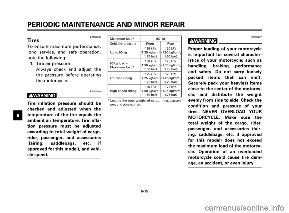
* Load is the total weight of cargo, rider, passen-
ger, and accessories.
Maximum load* 157 kg
Cold tire pressure: Front Rear
125 kPa 150 kPa
Up to 90 kg (1.25 kgf/cm
2, (1.50 kgf/cm2,1.25 bar) 1.50 bar)
90 kg load ~150 kPa 175 kPa
Maximum load*(1.50 kgf/cm
2, (1.75 kgf/cm2,1.50 bar) 1.75 bar)
Off-road riding125 kPa 125 kPa
(1.25 kgf/cm
2, (1.25 kgf/cm2,1.25 bar) 1.25 bar)
High-speed riding150 kPa 175 kPa
(1.50 kgf/cm
2, (1.75 kgf/cm2,
1.50 bar) 1.75 bar)
EAU00668Tires
To ensure maximum performance,
long service, and safe operation,
note the following:
1. Tire air pressure
Always check and adjust the
tire pressure before operating
the motorcycle.
EW000082
w
Tire inflation pressure should be
checked and adjusted when the
temperature of the tire equals the
ambient air temperature. Tire infla-
tion pressure must be adjusted
according to total weight of cargo,
rider, passenger, and accessories
(fairing, saddlebags, etc. if
approved for this model), and vehi-
cle speed.
5FY-9-E0 (TW200) 7/29/02 10:54 AM Page 44
Page 56 of 74

6-26
PERIODIC MAINTENANCE AND MINOR REPAIR
1
2
3
4
5
6
7
8
9
EAU00793Front fork inspection
EW000115
w
Securely support the motorcycle
so there is no danger of it falling
over.
1. Visual check
Check for scratches or damage
on the inner tube and exces-
sive oil leakage from the front
fork.2. Operation check
Place the motorcycle on a level
place.
a. Hold the motorcycle in an
upright position and apply the
front brake.
b. Push down hard on the han-
dlebars several times and
check if the fork rebounds
smoothly.
EC000098
cC
If any damage or unsmooth move-
ment is found with the front fork,
consult a Yamaha dealer.
EAU00794Steering inspection
Periodically inspect the condition
of the steering. Worn out or loose
steering bearings may be danger-
ous. Place a stand under the
engine to raise the front wheel off
the ground. Hold the lower end of
the front forks and try to move
them forward and backward. If any
free play can be felt, ask a Yamaha
dealer to inspect and adjust the
steering. Inspection is easier if the
front wheel is removed.
5FY-9-E0 (TW200) 7/29/02 10:54 AM Page 55
Page 57 of 74

6-27
PERIODIC MAINTENANCE AND MINOR REPAIR
1
2
3
4
5
6
7
8
9
EAU01144Wheel bearings
If there is play in the front or rear
wheel hub or if the wheel does not
turn smoothly, have a Yamaha
dealer inspect the wheel bearings.
EW000115
w
Securely support the motorcycle
so there is no danger of it falling
over.
EAU01071
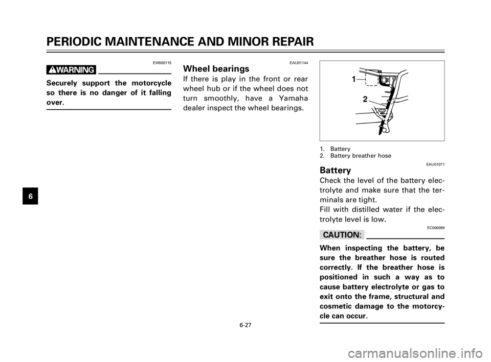
Battery
Check the level of the battery elec-
trolyte and make sure that the ter-
minals are tight.
Fill with distilled water if the elec-
trolyte level is low.
EC000099
cC
When inspecting the battery, be
sure the breather hose is routed
correctly. If the breather hose is
positioned in such a way as to
cause battery electrolyte or gas to
exit onto the frame, structural and
cosmetic damage to the motorcy-
cle can occur.
1
2
1. Battery
2. Battery breather hose
5FY-9-E0 (TW200) 7/29/02 10:54 AM Page 56
Page 60 of 74

6-30
PERIODIC MAINTENANCE AND MINOR REPAIR
1
2
3
4
5
6
7
8
9
1
3. Remove the connector and the
bulb holder cover.
4. Turn the bulb holder counter-
clockwise to remove it and
remove the defective bulb.
EW000119
w
Keep flammable products and your
hands away from a bulb while it is
on, as it is hot. Do not touch a bulb
until it cools down.
5. Put a new bulb into position
and secure it in place with the
bulb holder.
1. Bulb holder cover
EAU01191
Headlight bulb replacement
This motorcycle is equipped with a
quartz bulb headlight. If the head-
light bulb burns out, replace it as
follows:
1. Remove cowling A. (See page
6-6 for cowling removal and
installation procedures.)
2. Remove the headlight unit.
1
EC000105
cC
Avoid touching the glass part of a
bulb. Keep it free from oil; other-
wise, the transparency of the
glass, life of the bulb, and lumi-
nous flux will be adversely affect-
ed. If oil gets on a bulb, thoroughly
clean it with a cloth moistened
with alcohol or lacquer thinner.
6. Install the bulb holder cover,
connector and headlight unit.
7. Install the cowling.
8. If the headlight beam adjust-
ment is necessary, ask a
Yamaha dealer to make that
adjustment.
1. Bulb holder
5FY-9-E0 (TW200) 7/29/02 10:54 AM Page 59
Page 61 of 74

6-31
PERIODIC MAINTENANCE AND MINOR REPAIR
1
2
3
4
5
6
7
8
9
EAU00862
Supporting the motorcycle
Since the Yamaha TW200E has no
centerstand, follow these precau-
tions when removing the front and
rear wheel or performing other
maintenance requiring the motor-
cycle to stand upright.
Front wheel service:
To stabilize the rear of the motor-
cycle, either use a motorcycle
stand or place a motorcycle jack
under the frame in front of the rear
wheel to prevent it from moving
from side to side. Then use a
motorcycle stand to elevate the
front wheel off of the ground.
Rear wheel service:
Use a motorcycle stand or motor-
cycle jack to elevate the motorcycle
so the rear wheel is off the ground.
Alternatively, two jacks can be
placed under the frame or
swingarm.Check that the motorcycle is in a
stable and level position before
starting any maintenance. A strong
wooden box can be placed under
the engine for added stability.
3
2
41
EAU00908
Front wheel removalEW000122
w
8It is advisable to have a
Yamaha dealer service the
wheel.
8Securely support the motorcy-
cle so there is no danger of it
falling over.
1. Remove the clip holding the
speedometer cable in the
speedometer gear housing.
Then remove the speedometer
cable by pulling it outward.
1. Speedometer cable
2. Axle nut
3. Cotter pin
4. Clip
5FY-9-E0 (TW200) 7/29/02 10:54 AM Page 60
Page 63 of 74

6-33
PERIODIC MAINTENANCE AND MINOR REPAIR
1
2
3
4
5
6
7
8
9
EAU01304
Rear wheel removalEW000122
w
8It is advisable to have a
Yamaha dealer service the
wheel.
8Securely support the motorcy-
cle so there is no danger of it
falling over.
1. Remove the brake adjusting
nut and brake rod from the
brake cam lever.
1
2
3
4 5
1. Adjusting nut
2. Brake rod
3. Axle nut
4. Cotter pin
5. Chain adjusting plate
2. Remove the axle nut cotter pin
and loosen the axle nut.
3. Elevate the rear wheel by plac-
ing a suitable stand under the
engine.
4. Remove the axle nut.
5. Push the wheel forward and
remove the drive chain.
6. Pull out the axle and remove
the rear wheel assembly by
pulling it backwards.EAU01308
Rear wheel installation
1. Install the wheel assembly and
insert the axle from the left-
hand side. Be sure that the
chain adjusting plates are
installed with the punched side
outward and the slot in the
brake shoe plate is fit over the
stopper on the swingarm.
2. Install and adjust the drive
chain. (See page 6-22 for
details about adjusting the
drive chain slack.)
3. Install the axle nut and let the
motorcycle down.
4. Tighten the axle nut to the
specified torque and install the
axle nut cotter pin.
Tightening torque:
Axle nut:
90 Nm (9.0 m0kg)
5FY-9-E0 (TW200) 7/29/02 10:54 AM Page 62