AUX YAMAHA VERSITY 300 2004 Owners Manual
[x] Cancel search | Manufacturer: YAMAHA, Model Year: 2004, Model line: VERSITY 300, Model: YAMAHA VERSITY 300 2004Pages: 104, PDF Size: 2.82 MB
Page 17 of 104
EAU00027
INSTRUMENT AND CONTROL FUNCTIONS
Main switch/steering lock .................................................................... 3-1
Indicator lights ..................................................................................... 3-2
Speedometer ...................................................................................... 3-2
Fuel gauge .......................................................................................... 3-3
Battery voltage/coolant temperature gauge ........................................ 3-3
Multi-function display .......................................................................... 3-4
Anti-theft alarm (optional) .................................................................... 3-7
Handlebar switches ............................................................................. 3-8
Front brake lever ................................................................................. 3-9
Rear brake lever .................................................................................. 3-9
Fuel tank cap .................................................................................... 3-10
Fuel ................................................................................................... 3-10
Catalytic converter ............................................................................ 3-11
Seat ................................................................................................... 3-12
Storage compartments ...................................................................... 3-12
Anti-theft device housing ................................................................... 3-14
Adjusting the shock absorber assemblies ......................................... 3-14
Luggage hook ................................................................................... 3-15
Sidestand .......................................................................................... 3-16
Ignition circuit cut-off system ............................................................. 3-16
Auxiliary DC jack ............................................................................... 3-18
3
Page 18 of 104
3
INSTRUMENT AND CONTROL FUNCTIONS
PUSH
OPEN
ZAUM0253
WARNING
3-1
EAU00029
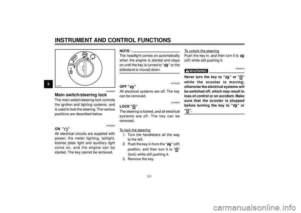
Main switch/steering lock
The main switch/steering lock controls
the ignition and lighting systems, and
is used to lock the steering. The various
positions are described below.
EAU00038
OFF ""
All electrical systems are off. The key
can be removed.
EAU00040
LOCK ""
The steering is locked, and all electrical
systems are off. The key can be
removed.
To lock the steering
1. Turn the handlebars all the way
to the left.
2. Push the key in from the "
" (off)
position, and then turn it to "
"
(lock) while still pushing it.
3. Remove the key.
To unlock the steering
Push the key in, and then turn it to
(off) while still pushing it.
EW000016
Never turn the key to "" or ""
while the scooter is moving,
otherwise the electrical systems will
be switched off, which may result in
loss of control or an accident. Make
sure that the scooter is stopped
before turning the key to "
" or
"".
EAU04580
ON ""
All electrical circuits are supplied with
power; the meter lighting, taillight,
license plate light and auxiliary light
come on, and the engine can be
started. The key cannot be removed.
NOTE :
The headlight comes on automatically
when the engine is started and stays
on until the key is turned to "
" or the
sidestand is moved down.
Page 35 of 104
INSTRUMENT AND CONTROL FUNCTIONS
3
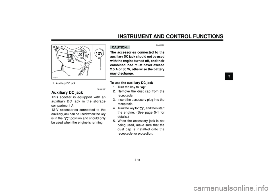
1. Auxiliary DC jack
EAUM0102*
Auxiliary DC jack
This scooter is equipped with an
auxiliary DC jack in the storage
compartment A.
12-V accessories connected to the
auxiliary jack can be used when the key
is in the "
" position and should only
be used when the engine is running.
EC000028*
The accessories connected to the
auxiliary DC jack should not be used
with the engine turned off, and their
combined load must never exceed
2.5 A or 30 W, otherwise the battery
may discharge.
To use the auxiliary DC jack
1. Turn the key to "
".
2. Remove the dust cap from the
receptacle.
3. Insert the accessory plug into the
receptacle.
4. Turn the key to "
", and then start
the engine. (See page 5-1 for
details.)
5. When the accessory jack is not
being used, make sure that the
dust cap is installed onto the
receptacle for protection.
CAUTION:
12V
1
ZAUM0417
3-18
Page 78 of 104

PERIODIC MAINTENANCE AND MINOR REPAIR
6
1. Backup fuse
2. Headlight fuse
3. Radiator fan fuse
4. Signaling system fuse
5. Ignition fuse
6. Auxiliary DC jack fuse
7. Spare fuse (x2)
8. Fuse tongs
CAUTION:
6-31
12345 776
8
ZAUM0460
The fuse block, which contains the fu-
ses for the individual circuits, is located
in the storage compartment A. (See
page 3-12 for storage compartment
opening and closing procedures.)If a fuse is blown, replace it as follows.
1. Turn the key to "
" and turn off
the electrical circuit in question.
2. Remove the blown fuse, and then
install a new fuse of the specified
amperage.
Specified fuses:
Main fuse Box
Main fuse: 30 A
Fuse block
Backup fuse 3 A
Headlight fuse: 15 A
Radiator fan fuse: 15 A
Signaling system fuse: 15 A
Ignition fuse: 7.5 A
Auxiliary DC jack fuse: 3 A3. Turn the key to "
" and turn on
the electrical circuit in question to
check if the device operates.
4. If the fuse immediately blows
again, have a Yamaha dealer
check the electrical system.
EC000103
Do not use a fuse of a higher
amperage rating than recommended
to avoid causing extensive damage
to the electrical system and possibly
a fire.
Page 94 of 104
SPECIFICATIONS
8
Wheels:
Front
Type Cast wheel
Size 14 x MT 2.75
Rear
Type Cast wheel
Size 14 x MT 4.00
Brakes:
Front
Type Single disc brake
Operation Right hand
Type brake fluid DOT 4
Rear
Type Single disc brake
Operation Left hand
Type brake fluid DOT 4
Suspension:
Front suspension Telescopic fork
Rear suspension Unit swing
Shock absorber:
Front fork type Coil spring/oil damper
Rear shock absorber Coil spring/oil damper
assembly type
Wheel travel:
Front wheel travel 108 mm
Rear wheel travel 120 mmElectrical:
Ignition system type Transistorized coil ignition
Charging system AC magneto
Battery
Model F9-12B
Voltage/capacity 12 V / 9 Ah
Headlight type:Halogen bulb
Bulbs (voltage/wattage x quantity):
Headlight 12V, 35W/35Wx2
Auxiliary light 12V, 5Wx2
Tail/brake light 12V, 5W/21Wx2
Turn signal light
Front 12V, 21Wx2
Rear 12V, 10Wx2
High beam indicator light LED
Turn signal indicator light LED
Headlight indicator light LED
Fuses:
Main fuse: 30 A
Backup fuse: 3 A
Headlight fuse: 15 A
Radiator fan fuse: 15 A
Signaling system fuse: 15 A
Ignition fuse: 7.5 A
Auxiliary DC jack fuse: 3 A
Reserve fuse (x quantity) 30Ax1, 15Ax1, 7.5Ax1
8-3
Page 100 of 104
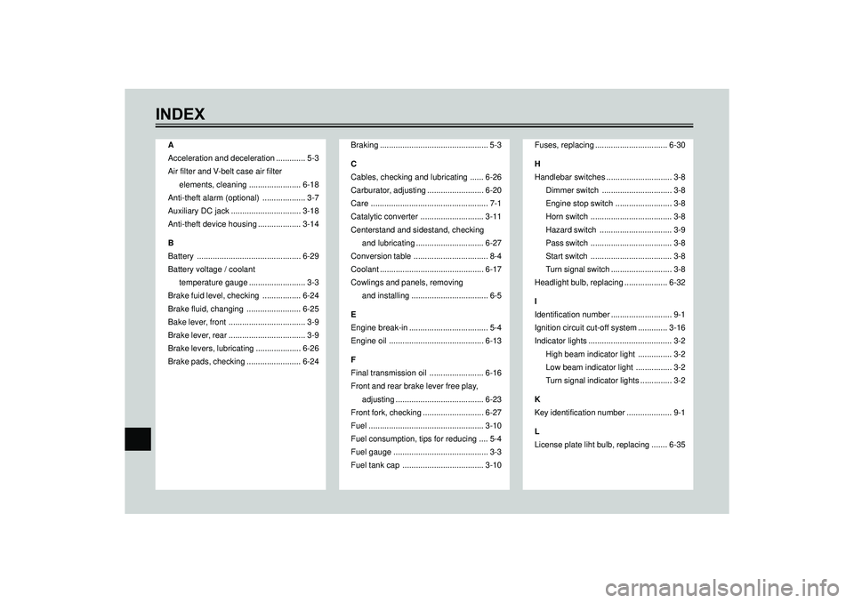
INDEX
A
Acceleration and deceleration ............. 5-3
Air filter and V-belt case air filter
elements, cleaning ....................... 6-18
Anti-theft alarm (optional) ................... 3-7
Auxiliary DC jack ............................... 3-18
Anti-theft device housing ................... 3-14
B
Battery .............................................. 6-29
Battery voltage / coolant
temperature gauge ......................... 3-3
Brake fuid level, checking ................. 6-24
Brake fluid, changing ........................ 6-25
Bake lever, front .................................. 3-9
Brake lever, rear .................................. 3-9
Brake levers, lubricating .................... 6-26
Brake pads, checking ........................ 6-24Braking ................................................ 5-3
C
Cables, checking and lubricating ...... 6-26
Carburator, adjusting ......................... 6-20
Care .................................................... 7-1
Catalytic converter ............................ 3-11
Centerstand and sidestand, checking
and lubricating .............................. 6-27
Conversion table ................................. 8-4
Coolant .............................................. 6-17
Cowlings and panels, removing
and installing .................................. 6-5
E
Engine break-in ................................... 5-4
Engine oil .......................................... 6-13
F
Final transmission oil ........................ 6-16
Front and rear brake lever free play,
adjusting ....................................... 6-23
Front fork, checking ........................... 6-27
Fuel ................................................... 3-10
Fuel consumption, tips for reducing .... 5-4
Fuel gauge .......................................... 3-3
Fuel tank cap .................................... 3-10Fuses, replacing ................................ 6-30
H
Handlebar switches ............................. 3-8
Dimmer switch ............................... 3-8
Engine stop switch ......................... 3-8
Horn switch .................................... 3-8
Hazard switch ................................ 3-9
Pass switch .................................... 3-8
Start switch .................................... 3-8
Turn signal switch ........................... 3-8
Headlight bulb, replacing ................... 6-32
I
Identification number ........................... 9-1
Ignition circuit cut-off system ............. 3-16
Indicator lights ..................................... 3-2
High beam indicator light ............... 3-2
Low beam indicator light ................ 3-2
Turn signal indicator lights .............. 3-2
K
Key identification number .................... 9-1
L
License plate liht bulb, replacing ....... 6-35