coolant temperature YAMAHA VERSITY 300 2004 Owners Manual
[x] Cancel search | Manufacturer: YAMAHA, Model Year: 2004, Model line: VERSITY 300, Model: YAMAHA VERSITY 300 2004Pages: 104, PDF Size: 2.82 MB
Page 17 of 104
EAU00027
INSTRUMENT AND CONTROL FUNCTIONS
Main switch/steering lock .................................................................... 3-1
Indicator lights ..................................................................................... 3-2
Speedometer ...................................................................................... 3-2
Fuel gauge .......................................................................................... 3-3
Battery voltage/coolant temperature gauge ........................................ 3-3
Multi-function display .......................................................................... 3-4
Anti-theft alarm (optional) .................................................................... 3-7
Handlebar switches ............................................................................. 3-8
Front brake lever ................................................................................. 3-9
Rear brake lever .................................................................................. 3-9
Fuel tank cap .................................................................................... 3-10
Fuel ................................................................................................... 3-10
Catalytic converter ............................................................................ 3-11
Seat ................................................................................................... 3-12
Storage compartments ...................................................................... 3-12
Anti-theft device housing ................................................................... 3-14
Adjusting the shock absorber assemblies ......................................... 3-14
Luggage hook ................................................................................... 3-15
Sidestand .......................................................................................... 3-16
Ignition circuit cut-off system ............................................................. 3-16
Auxiliary DC jack ............................................................................... 3-18
3
Page 20 of 104
3
INSTRUMENT AND CONTROL FUNCTIONS
EAUM0098
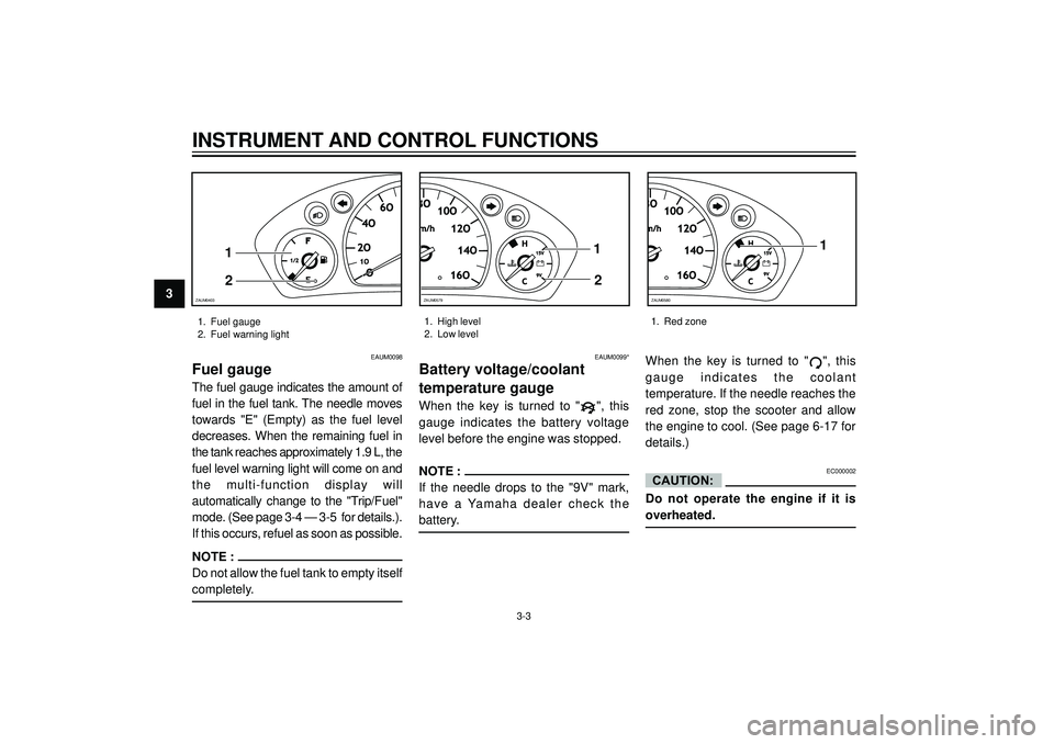
Fuel gauge
The fuel gauge indicates the amount of
fuel in the fuel tank. The needle moves
towards "E" (Empty) as the fuel level
decreases. When the remaining fuel in
the tank reaches approximately 1.9 L, the
fuel level warning light will come on and
the multi-function display will
automatically change to the "Trip/Fuel"
mode. (See page 3-4 — 3-5 for details.).
If this occurs, refuel as soon as possible.
NOTE :
Do not allow the fuel tank to empty itself
completely.
EAUM0099*
Battery voltage/coolant
temperature gauge
When the key is turned to "", this
gauge indicates the battery voltage
level before the engine was stopped.
NOTE :
If the needle drops to the "9V" mark,
have a Yamaha dealer check the
battery.When the key is turned to "
", this
gauge indicates the coolant
temperature. If the needle reaches the
red zone, stop the scooter and allow
the engine to cool. (See page 6-17 for
details.)
EC000002
Do not operate the engine if it is
overheated.
CAUTION:
1. Fuel gauge
2. Fuel warning light1. High level
2. Low level1. Red zone
O1O1O
2O2O
4O4O
6O6O
F
1/21/2
E
1
2
ZAUM0403
3-3
10O10O
12O12O
14O14O
16O16O
H
C15V15V
9V9V
1
2
ZAUM0579
10O
12O
14O
16O
H
C15V 15V
9V 9V1
ZAUM0580
Page 64 of 104
PERIODIC MAINTENANCE AND MINOR REPAIR
6
EAU04591*
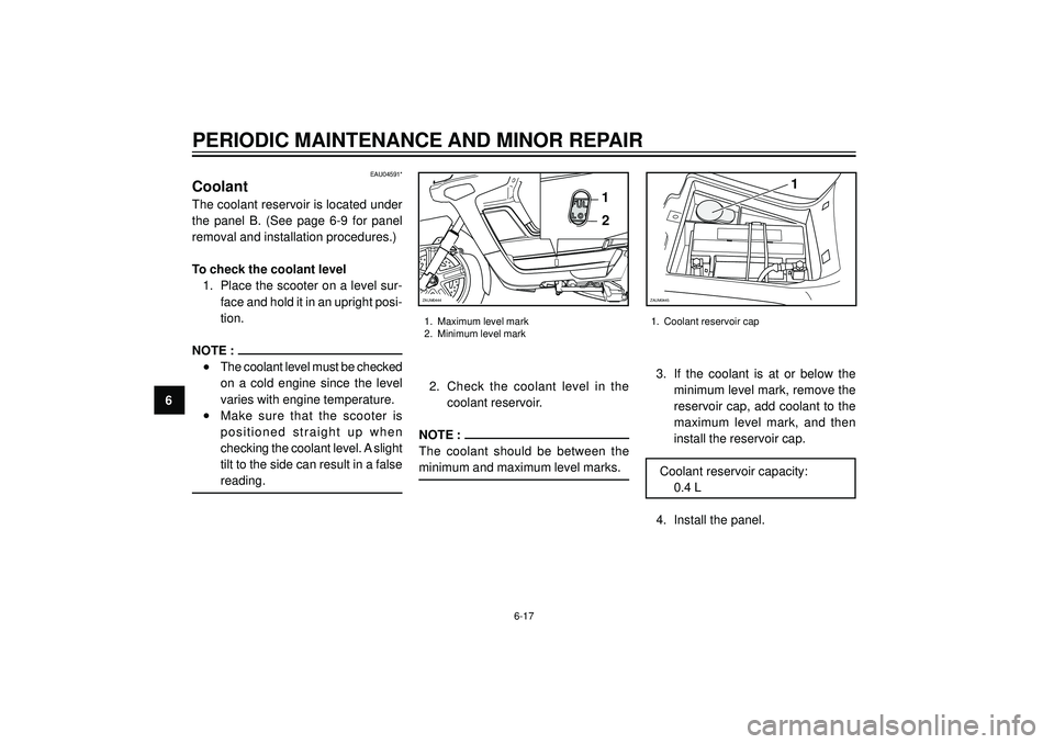
Coolant
The coolant reservoir is located under
the panel B. (See page 6-9 for panel
removal and installation procedures.)
To check the coolant level
1. Place the scooter on a level sur-
face and hold it in an upright posi-
tion.
NOTE :
•The coolant level must be checked
on a cold engine since the level
varies with engine temperature.
•Make sure that the scooter is
positioned straight up when
checking the coolant level. A slight
tilt to the side can result in a false
reading.2. Check the coolant level in the
coolant reservoir.
NOTE :
The coolant should be between the
minimum and maximum level marks.
1. Maximum level mark
2. Minimum level mark
3. If the coolant is at or below the
minimum level mark, remove the
reservoir cap, add coolant to the
maximum level mark, and then
install the reservoir cap.
Coolant reservoir capacity:
0.4 L
4. Install the panel.
1. Coolant reservoir cap
6-17
1
2
ZAUM0444
1
ZAUM0445
Page 65 of 104
PERIODIC MAINTENANCE AND MINOR REPAIR
6
EC000080
•If coolant is not available, use
distilled water or soft tap water
instead. Do not use hard water or
salt water since it is harmful to
the engine.
•If water has been used instead of
coolant, replace it with coolant as
soon as possible, otherwise the
engine may not be sufficiently
cooled and the cooling system
will not be protected against frost
and corrosion.
•If water has been added to the
coolant, have a Yamaha dealer
check the antifreeze content of
the coolant as soon as possible,
otherwise the effectiveness of the
coolant will be reduced.
NOTE :
The radiator fan is automatically
switched on or off according to the
coolant temperature in the radiator. If
the engine overheats, see page 6-37
for further instructions.
CAUTION:EAU03627*
Air filter and V-belt case air
filter elements
The air filter and V-belt case air filter
elements should be cleaned at the
intervals specified in the periodic main-
tenance and lubrication chart. Clean
both filter elements more frequently if
you are riding in unusually wet or dusty
areas.
EC000092*
•Make sure that each filter
element is properly seated in its
case.
•The engine should never be
operated without the filter
elements installed, otherwise
the piston and/or cylinder may
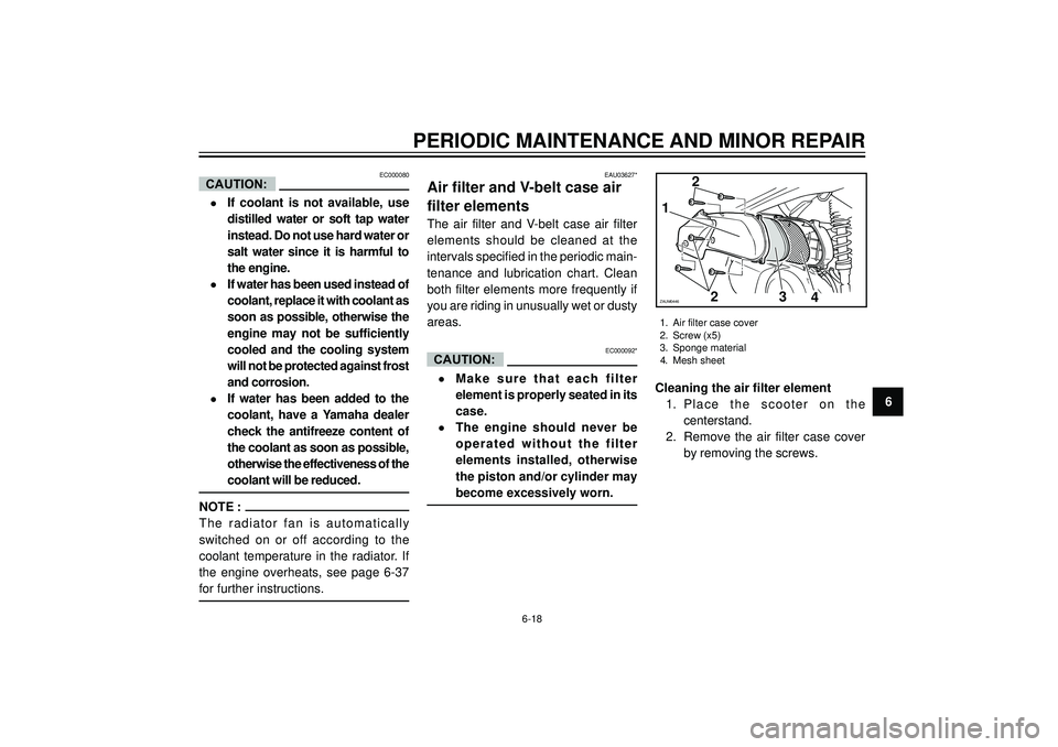
become excessively worn.Cleaning the air filter element
1. Place the scooter on the
centerstand.
2. Remove the air filter case cover
by removing the screws.
CAUTION:
1. Air filter case cover
2. Screw (x5)
3. Sponge material
4. Mesh sheet
6-18
1
2 2
34ZAUM0446
Page 100 of 104
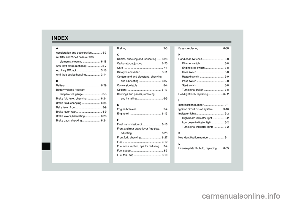
INDEX
A
Acceleration and deceleration ............. 5-3
Air filter and V-belt case air filter
elements, cleaning ....................... 6-18
Anti-theft alarm (optional) ................... 3-7
Auxiliary DC jack ............................... 3-18
Anti-theft device housing ................... 3-14
B
Battery .............................................. 6-29
Battery voltage / coolant
temperature gauge ......................... 3-3
Brake fuid level, checking ................. 6-24
Brake fluid, changing ........................ 6-25
Bake lever, front .................................. 3-9
Brake lever, rear .................................. 3-9
Brake levers, lubricating .................... 6-26
Brake pads, checking ........................ 6-24Braking ................................................ 5-3
C
Cables, checking and lubricating ...... 6-26
Carburator, adjusting ......................... 6-20
Care .................................................... 7-1
Catalytic converter ............................ 3-11
Centerstand and sidestand, checking
and lubricating .............................. 6-27
Conversion table ................................. 8-4
Coolant .............................................. 6-17
Cowlings and panels, removing
and installing .................................. 6-5
E
Engine break-in ................................... 5-4
Engine oil .......................................... 6-13
F
Final transmission oil ........................ 6-16
Front and rear brake lever free play,
adjusting ....................................... 6-23
Front fork, checking ........................... 6-27
Fuel ................................................... 3-10
Fuel consumption, tips for reducing .... 5-4
Fuel gauge .......................................... 3-3
Fuel tank cap .................................... 3-10Fuses, replacing ................................ 6-30
H
Handlebar switches ............................. 3-8
Dimmer switch ............................... 3-8
Engine stop switch ......................... 3-8
Horn switch .................................... 3-8
Hazard switch ................................ 3-9
Pass switch .................................... 3-8
Start switch .................................... 3-8
Turn signal switch ........................... 3-8
Headlight bulb, replacing ................... 6-32
I
Identification number ........................... 9-1
Ignition circuit cut-off system ............. 3-16
Indicator lights ..................................... 3-2
High beam indicator light ............... 3-2
Low beam indicator light ................ 3-2
Turn signal indicator lights .............. 3-2
K
Key identification number .................... 9-1
L
License plate liht bulb, replacing ....... 6-35