display YAMAHA VERSITY 300 2004 Owners Manual
[x] Cancel search | Manufacturer: YAMAHA, Model Year: 2004, Model line: VERSITY 300, Model: YAMAHA VERSITY 300 2004Pages: 104, PDF Size: 2.82 MB
Page 16 of 104
2
DESCRIPTION
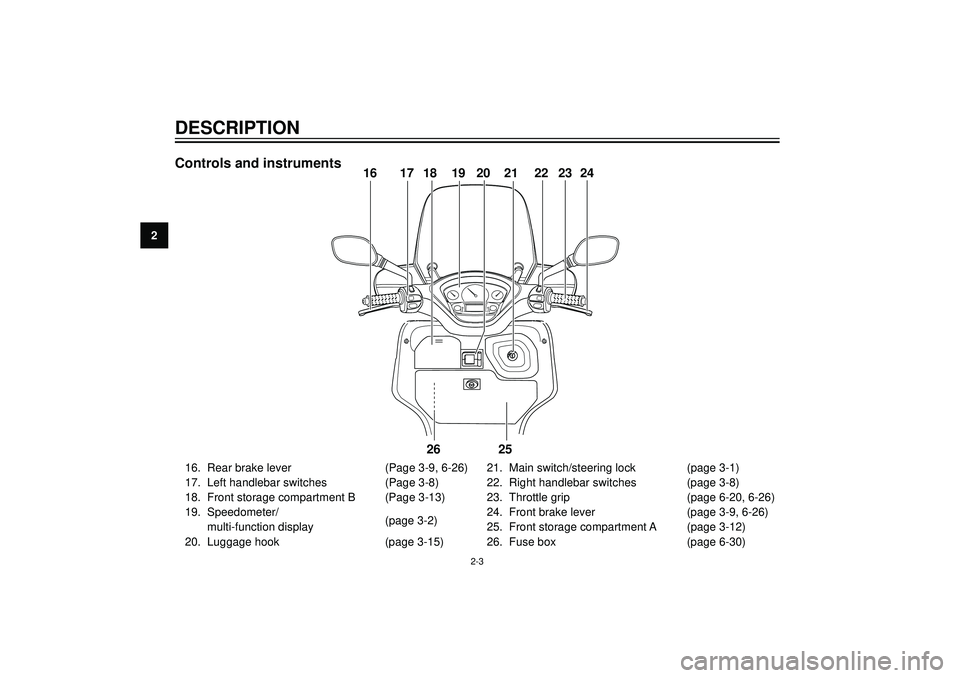
Controls and instruments
PUSHOPEN
16 17 18 19 20 21 22 2423
25 26
16. Rear brake lever (Page 3-9, 6-26)
17. Left handlebar switches (Page 3-8)
18. Front storage compartment B (Page 3-13)
19. Speedometer/
multi-function display(page 3-2)
20. Luggage hook (page 3-15)21. Main switch/steering lock (page 3-1)
22. Right handlebar switches (page 3-8)
23. Throttle grip (page 6-20, 6-26)
24. Front brake lever (page 3-9, 6-26)
25. Front storage compartment A (page 3-12)
26. Fuse box (page 6-30)
2-3
Page 17 of 104
EAU00027
INSTRUMENT AND CONTROL FUNCTIONS
Main switch/steering lock .................................................................... 3-1
Indicator lights ..................................................................................... 3-2
Speedometer ...................................................................................... 3-2
Fuel gauge .......................................................................................... 3-3
Battery voltage/coolant temperature gauge ........................................ 3-3
Multi-function display .......................................................................... 3-4
Anti-theft alarm (optional) .................................................................... 3-7
Handlebar switches ............................................................................. 3-8
Front brake lever ................................................................................. 3-9
Rear brake lever .................................................................................. 3-9
Fuel tank cap .................................................................................... 3-10
Fuel ................................................................................................... 3-10
Catalytic converter ............................................................................ 3-11
Seat ................................................................................................... 3-12
Storage compartments ...................................................................... 3-12
Anti-theft device housing ................................................................... 3-14
Adjusting the shock absorber assemblies ......................................... 3-14
Luggage hook ................................................................................... 3-15
Sidestand .......................................................................................... 3-16
Ignition circuit cut-off system ............................................................. 3-16
Auxiliary DC jack ............................................................................... 3-18
3
Page 20 of 104
3
INSTRUMENT AND CONTROL FUNCTIONS
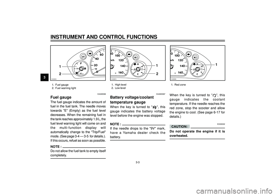
EAUM0098
Fuel gauge
The fuel gauge indicates the amount of
fuel in the fuel tank. The needle moves
towards "E" (Empty) as the fuel level
decreases. When the remaining fuel in
the tank reaches approximately 1.9 L, the
fuel level warning light will come on and
the multi-function display will
automatically change to the "Trip/Fuel"
mode. (See page 3-4 — 3-5 for details.).
If this occurs, refuel as soon as possible.
NOTE :
Do not allow the fuel tank to empty itself
completely.
EAUM0099*
Battery voltage/coolant
temperature gauge
When the key is turned to "", this
gauge indicates the battery voltage
level before the engine was stopped.
NOTE :
If the needle drops to the "9V" mark,
have a Yamaha dealer check the
battery.When the key is turned to "
", this
gauge indicates the coolant
temperature. If the needle reaches the
red zone, stop the scooter and allow
the engine to cool. (See page 6-17 for
details.)
EC000002
Do not operate the engine if it is
overheated.
CAUTION:
1. Fuel gauge
2. Fuel warning light1. High level
2. Low level1. Red zone
O1O1O
2O2O
4O4O
6O6O
F
1/21/2
E
1
2
ZAUM0403
3-3
10O10O
12O12O
14O14O
16O16O
H
C15V15V
9V9V
1
2
ZAUM0579
10O
12O
14O
16O
H
C15V 15V
9V 9V1
ZAUM0580
Page 21 of 104
INSTRUMENT AND CONTROL FUNCTIONS
3
"Mode""Mode"
"Mode"
"Mode"
12
3
4
ZAUM0391
1. Mode button
2. Digital display
3. Set button1. Total
2. Trip 1
3. Trip 2
4. Trip/Fuel
3-4
1
23ZAUM0581
EAUM1950
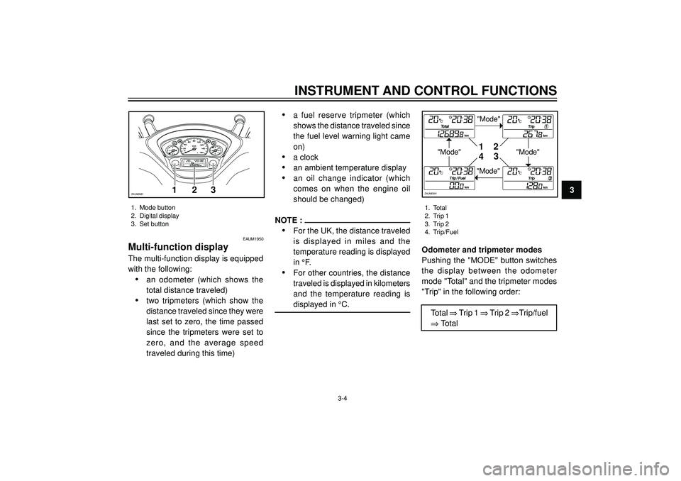
Multi-function display
The multi-function display is equipped
with the following:
•an odometer (which shows the
total distance traveled)
•two tripmeters (which show the
distance traveled since they were
last set to zero, the time passed
since the tripmeters were set to
zero, and the average speed
traveled during this time)
•a fuel reserve tripmeter (which
shows the distance traveled since
the fuel level warning light came
on)
•a clock
•an ambient temperature display
•an oil change indicator (which
comes on when the engine oil
should be changed)
NOTE :
•For the UK, the distance traveled
is displayed in miles and the
temperature reading is displayed
in °F.
•For other countries, the distance
traveled is displayed in kilometers
and the temperature reading is
displayed in °C.Odometer and tripmeter modes
Pushing the "MODE" button switches
the display between the odometer
mode "Total" and the tripmeter modes
"Trip" in the following order:
Total ⇒ Trip 1 ⇒ Trip 2 ⇒Trip/fuel
⇒ Total
Page 22 of 104
3
INSTRUMENT AND CONTROL FUNCTIONS
"Set"
"Set""Set"
1
2
3
ZAUM0392ZAUM0393
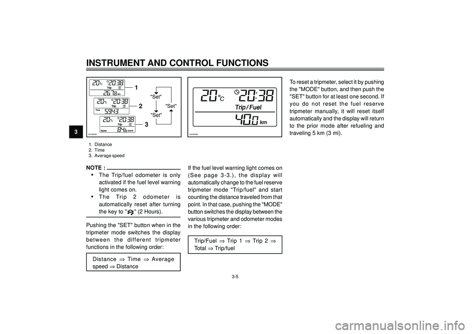
1. Distance
2. Time
3. Average speed
3-5
NOTE :
•The Trip/fuel odometer is only
activated if the fuel level warning
light comes on.
•The Trip 2 odometer is
automatically reset after turning
the key to "" (2 Hours).
Pushing the "SET" button when in the
tripmeter mode switches the display
between the different tripmeter
functions in the following order:
Distance ⇒ Time ⇒ Average
speed ⇒ DistanceIf the fuel level warning light comes on
(See page 3-3.), the display will
automatically change to the fuel reserve
tripmeter mode "Trip/fuel" and start
counting the distance traveled from that
point. In that case, pushing the "MODE"
button switches the display between the
various tripmeter and odometer modes
in the following order:
Trip/Fuel ⇒ Trip 1 ⇒ Trip 2 ⇒
Total ⇒ Trip/fuelTo reset a tripmeter, select it by pushing
the "MODE" button, and then push the
"SET" button for at least one second. If
you do not reset the fuel reserve
tripmeter manually, it will reset itself
automatically and the display will return
to the prior mode after refueling and
traveling 5 km (3 mi).
Page 23 of 104
INSTRUMENT AND CONTROL FUNCTIONS
3ZAUM0394ZAUM0395
1
2
3
ZAUM0396
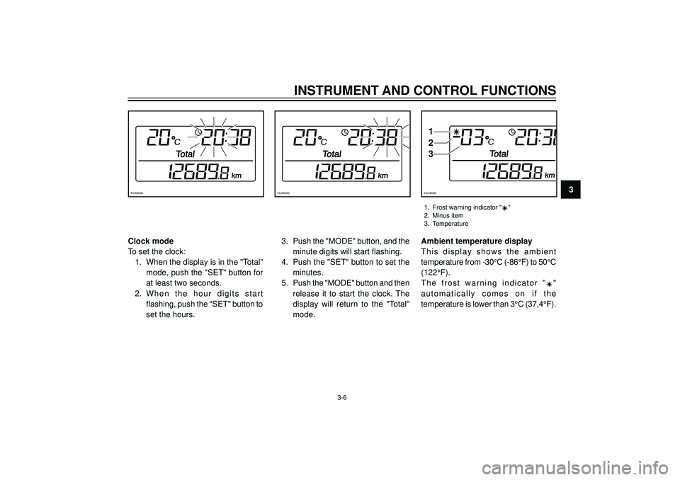
1. Frost warning indicator ""
2. Minus item
3. Temperature
3-6
Clock mode
To set the clock: 1. When the display is in the "Total" mode, push the "SET" button for
at least two seconds.
2. When the hour digits start flashing, push the "SET" button to
set the hours. 3. Push the "MODE" button, and the
minute digits will start flashing.
4. Push the "SET" button to set the minutes.
5. Push the "MODE" button and then
release it to start the clock. The
display will return to the "Total"
mode. Ambient temperature display
This display shows the ambient
temperature from -30
°C (-86 °F) to 50 °C
(122 °F).
The frost warning indicator "
"
automatically comes on if the
temperature is lower than 3 °C (37,4 °F).
Page 101 of 104
INDEX
Storage compartments ...................... 3-12
T
Tail/brake light bulb or rear turn
signal light bulb, replacing ............ 6-34
Throtlle cable free play, adjusting ...... 6-20
Throttle grip and cable,
checking and lubricating .............. 6-26
Tires .................................................. 6-21
Tool kit ................................................. 6-1
Troubleshooting ................................. 6-35
Troubleshooting charts ...................... 6-36
Turn signal light bulb (front),
replacing ...................................... 6-34
V
Valve clearance, adjusting ................ 6-21
Vehicule identification number ............ 9-1
W
Wheel bearing, checking ................... 6-29
Wheels .............................................. 6-23 Luggage hook ................................... 3-15
M
Main switch/steering lock .................... 3-1
Model label .......................................... 9-2
Multi-function display .......................... 3-4
P
Parking ................................................ 5-5
Part locations ...................................... 2-1
Periodic maintenance and lubrication
chart ............................................... 6-2
Pre-operation check list ...................... 4-1
S
Safe-riding points ................................ 1-2
Seat ................................................... 3-12
Shock absorber assemblies,
adjusting ....................................... 3-14
Sidestand .......................................... 3-16
Spark plug, checking ......................... 6-11
Specifications ...................................... 8-1
Speedometer ...................................... 3-2
Starting off .......................................... 5-2
Starting the engine .............................. 5-1
Steering, checking ............................ 6-28
Storage ............................................... 7-3